Table of Contents
Advertisement
Quick Links
MP105E
M-232 Linear Actuator
User Manual
Version: 1.2
Date: 31.08.2020
This document describes the following
high-resolution linear actuators with limit
switches:
M-232.17
DC Drive, Travel Range 17 mm
M-232.17S
Stepper Motor Drive, Travel Range 17 mm
Physik Instrumente (PI) GmbH & Co. KG · Auf der Römerstr. 1 76228 Karlsruhe, Germany
Telephon +49 721 4846-0 · Telefax +49 721 4846-1019 · E-Mail info@pi.ws
Advertisement
Table of Contents

Related Manuals for PI M-232.17


Summary of Contents for PI M-232.17
- Page 1 DC Drive, Travel Range 17 mm M-232.17S Stepper Motor Drive, Travel Range 17 mm Physik Instrumente (PI) GmbH & Co. KG · Auf der Römerstr. 1 76228 Karlsruhe, Germany Telephon +49 721 4846-0 · Telefax +49 721 4846-1019 · E-Mail info@pi.ws...
- Page 2 With regard thereto, Physik Instrumente (PI) GmbH & Co. KG retains all the rights. Use of said text, photographs and drawings is permitted only in part and only upon citation of the source.
-
Page 3: Table Of Contents
Contents About this Document Goal and Target Audience of this Manual ............1 Symbols and Typographic Conventions ............... 1 Other Applicable Documents ................2 Safety Intended Use ......................3 General Safety Instructions .................. 3 2.2.1 Organizational Measures ..............3 2.2.2 Safety Measures during Installation ........... - Page 4 Start-Up General Notes on Start-Up .................27 Starting Up the Actuator ..................29 6.2.1 M-232 Entries in the Stage Database of PI ........31 Maintenance General Notes on Maintenance ................33 Lubricating the M-232 ..................33 Cleaning the M-232 ....................34 Troubleshooting Customer Service Technical Data 10.1...
-
Page 5: About This Document
1 About this Document About this Document 1.1 Goal and Target Audience of this Manual This manual contains information on the intended use of the M-232. It assumes that the reader has a fundamental understanding of basic servo systems as well as motion control concepts and applicable safety procedures. For updated releases of this user manual, or if you have any questions, contact our customer service department (p. -
Page 6: Other Applicable Documents
1 About this Document Symbol Meaning Action consisting of several steps whose sequential order must be observed Action consisting of one or several steps whose sequential order is irrelevant List item p. 5 Cross-reference to page 5 RS-232 Labeling of an operating element on the product (example: socket of the RS-232 interface) 1.3 Other Applicable Documents... -
Page 7: Safety
2 Safety Safety 2.1 Intended Use The M-232 is a laboratory device as defined by DIN EN 61010-1. It is intended to be used in interior spaces and in an environment which is free of dirt, oil, and lubricants. Based on its design and realization, the M-232 is intended for positioning, adjusting and shifting loads in one axis at various velocities. -
Page 8: Safety Measures During Installation
2 Safety If you pass the M-232 on to other users, also turn over this user manual as well as all other relevant information provided by the manufacturer. Only use the device on the basis of the complete user manual. Missing information due to an incomplete user manual can lead to slight injury as well as property damage. -
Page 9: Safety Measures During Start-Up
2 Safety 2.2.3 Safety Measures during Start-Up A motorized linear actuator can generate powerful forces depending on the gear ratio. Connecting a linear actuator to an unsuitable controller can cause damage to the linear actuator or controller. Connect a linear actuator with DC motor to a DC motor controller only. ... -
Page 10: Safety Measures During Maintenance
2 Safety Oscillations Imprecise approach of the position Settling time is too long If the performance of the M-232 is not satisfactory, check the settings for the servo-control parameters of your controller. 2.2.5 Safety Measures during Maintenance The M-232 is precisely aligned. -
Page 11: Product Description
3 Product Description Product Description M-232 Linear Actuator MP105E Version: 1.2... -
Page 12: System Overview
Peripheral control equipment Loads configurations and control PC software (e.g. PIMikroMove) commands to the controller (e.g. included in the scope of delivery PC in connection with PC of PI controllers. software). Controller Controls the motions of the Stand-alone device or motor actuator. -
Page 13: Features And Applications
Peripheral control equipment Transmission cable between to controller: PC and controller. Ensures the data Included in the scope of communication. delivery of PI controllers. Controller to actuator: Transmission cable between Ensures the data controller and actuator: communication and the Part of the actuator or power source of the actuator. -
Page 14: Model Overview
Compact High-Resolution Stepper Mike Linear Actuator, 17 mm, Limit Switches For further technical data, see the specifications (p. 39). PI also produces custom designs upon request. Custom designs can differ from the described standard products in respect to dimensions, characteristics or other technical data. -
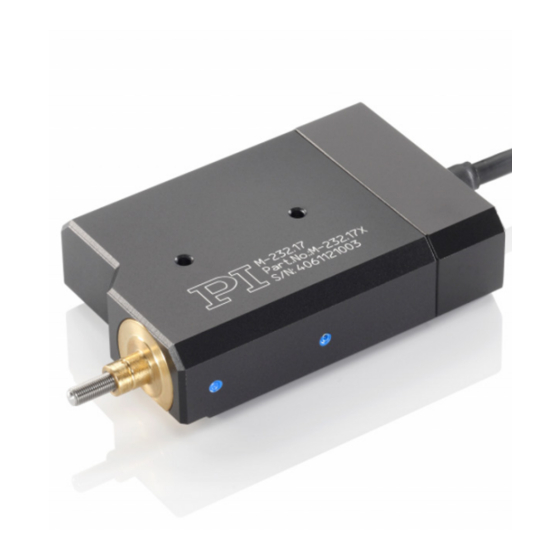
Page 15: Product View
3 Product Description 3.4 Product View Figure 2: Product view Moving pusher, rotating, with M3.5 thread and convex end Mounting shaft with circumferential groove Locating surface Continuous mounting hole, M3 thread Case Cable for connecting to the controller 3.5 Scope of Delivery Order Number Items M-232... -
Page 16: Suitable Controllers
The M-232 must be connected to a suitable controller (see Data Table, p. 39). The required PC software is included in the scope of delivery of the PI controllers. The operation of the controllers is described in the corresponding user manuals. -
Page 17: Unpacking
3. Inspect the contents for signs of damage. If parts are missing or you notice signs of damage, contact PI immediately. 4. Keep all packaging materials in case the product needs to be returned. M-232 Linear Actuator MP105E Version: 1.2... -
Page 19: Installation
5 Installation Installation 5.1 General Notes on Installation NOTICE Cable break! A cable break leads to a failure of the linear actuator. Install the linear actuator so that the cable is not bent or squeezed too severely during operation. NOTICE Increased friction! Lateral forces that affect the pusher of the linear actuator increase the friction on the... -
Page 20: Installing The Actuator In A Mechanical Mounting
Suitable mechanical mounting PI micropositioning stages / fiber positioning systems of the types M-105 and M- The necessary steps are described in the following sections. INFORMATION To achieve an optimum repeatability, the mounting shaft must not have any backlash. -
Page 21: Providing A Suitable Mechanical Mounting And Installation Environment
5 Installation 5.2.1 Providing a Suitable Mechanical Mounting and Installation Environment Figure 3: Components, installation dimensions (in mm) Pusher, rotating, with M3.5 thread and R3 convex end Mounting shaft with width (a): 2.5 mm width (c) 3.5 mm diameter (e): 6 mm Circumferential groove for mounting a mounting screw, V profile with width (b): 1 mm angle to the vertical axis: ±45°... - Page 22 5 Installation Figure 4: Example for the installation of a linear actuator (here: an M-235) A suitable mechanical mounting and installation environment are necessary for the proper use of the actuator. Make sure that the following conditions have been met: −...
-
Page 23: Installing The Actuator In A Mechanical Mounting
5 Installation Avoid or label danger areas that result from the installation of the actuator and from use, in accordance with the legal regulations (e.g. risk of crushing in the case of heavy moving loads, fast actuator motions and/or high drive torques). ... - Page 24 5 Installation Figure 5: Example for the installation in a mechanical mounting, sectional view Mechanical Mounting Mounting screw (e.g. M2 grub screw) Mounting shaft with circumferential groove Sleeve / case of the actuator We recommend fixing the actuator with at least one mounting screw, which is screwed into each mechanical mounting and engages in the groove of the mounting shaft.
-
Page 25: Installing The Actuator In A Micropositioning Stage
4. Check that the actuator is correctly fitted in the mounting. 5.3 Installing the Actuator in a Micropositioning Stage The M-232 is suitable, e.g., for installation in a PI micropositioning stage / -fiber positioning system of the type M-105 or M-106. - Page 26 5 Installation Tools and accessories AF 1.5 Allen wrench for M2 grub screw or corresponding screwdriver Micropositioning stage with suitable mounting for the linear actuator. Installing the actuator in a micropositioning stage Figure 6: Actuator and stage, schematic Moving platform (internal) (Wide) micropositioning stage front with (a) horizontal hole...
- Page 27 5 Installation 2. Unscrew the grub screw in the middle of the front of the micropositioning stage by around three rotations using an Allen wrench or screwdriver. Figure 7: Unscrew the grub screw slightly 3. Align the actuator so that the following conditions are met: −...
- Page 28 5 Installation 4. Insert the mounting shaft of the actuator into the horizontal hole on the front of the micropositioning stage until the locating surface of the actuator and the front of the micropositioning stage touch. The grub screw is then precisely above the circumferential groove of the mounting shaft.
- Page 29 5 Installation Figure 11: Complete installation: M-232 actuator in a micropositioning stage (here: M-105) Moving platform of the micropositioning stage Pusher of the M-232 actuator, here completely extended Mounting screw: M2 grub screw Locating surface of the M-232 actuator, flush with the top edge of the front of the micropositioning stage M-232 Linear Actuator MP105E...
-
Page 31: Start-Up
6 Start-Up Start-Up 6.1 General Notes on Start-Up CAUTION Unintentional motion of the linear actuator while connecting it to the motor controller! Do not place any objects in areas where they can get caught by moving parts. Keep your fingers at a safe distance from the motion range of the linear actuator. NOTICE Damage if a wrong motor controller is connected! Connecting a linear actuator to an unsuitable controller can cause damage to the... - Page 32 6 Start-Up NOTICE Damage or major wear to the mechanical system as a result of high acceleration! In the event of a malfunction of the motor controller, stop the motion immediately. Ensure that the end of the travel range is approached at low velocity. ...
-
Page 33: Starting Up The Actuator
Suitable controller (p. 12) - motor controller card for PC installation or stand- alone device incl. connection cable to PC. PC software for the controller (for PI controllers: included in their scope of delivery) If necessary, suitable motor cable from PI:... - Page 34 6 Start-Up Starting up the actuator 1. If you use a motor controller card (e.g. C-843 from PI), make sure that it is properly installed or install it (see the user manual of the motor controller card). 2. If suitable and current PC software for the controller is not on your PC yet, install the PC software (see the user manual of the controller or the software).
-
Page 35: M-232 Entries In The Stage Database Of Pi
6 Start-Up 6.2.1 M-232 Entries in the Stage Database of PI For motor controllers from PI you can select the connected linear actuator from a stage database in the respective PC software. The appropriate operating parameters are thus loaded into the motor controller. You can find a detailed description in the user manual for the motor controller or in the manual for the PC software used. -
Page 37: Maintenance
7 Maintenance Maintenance 7.1 General Notes on Maintenance NOTICE Damage due to improper maintenance! The M-232 can become misaligned as a result of improper maintenance. Do not loosen any sealed screws. 7.2 Lubricating the M-232 Depending on the operational conditions and the period of use of the linear actuator, the following maintenance measures are required. -
Page 38: Cleaning The M-232
7 Maintenance 7.3 Cleaning the M-232 Prerequisites You have disconnected the linear actuator from the controller. Cleaning the linear actuator When necessary, clean the linear actuator surface with a towel lightly dampened with a mild cleanser or disinfectant. ... -
Page 39: Troubleshooting
0.3 Nm. Functional impairment Motor controller has been Motor controller from PI: after system modification replaced Load the parameters from the stage database that correspond to the combination of motor controller and M-232 model (p. -
Page 41: Customer Service
9 Customer Service Customer Service For inquiries and orders, contact your PI sales engineer or send us an e-mail (mailto:service@pi.de). If you have questions concerning your system, have the following information ready: Product codes and serial numbers of all products in the system ... -
Page 43: Technical Data
10 Technical Data 10 Technical Data 10.1 Specifications 10.1.1 Data Table M-232.17 Unit Tolerance Motion and positioning Travel range Integrated sensor Rotary encoder Sensor resolution 2048 Cts./rev. Design resolution 0.007 µm Typ. Minimum incremental motion µm Typ. Backlash µm Typ. -
Page 44: Ambient Conditions And Classifications
10 Technical Data M-232.17 Unit Tolerance Miscellaneous M-232.17 Operating temperature range -20 to 65 °C Aluminum anodized, chrome Material steel Mass 0.17 ±5 % Cable length ±10 mm D-sub 15 (m), incl. encoder Connector driver C-863 Recommended controllers / drivers C-884 10.1.2 Ambient Conditions and Classifications... -
Page 45: Limit Switch Specifications
10 Technical Data 10.1.3 Limit Switch Specifications Type Magnetic (Hall-effect) sensor Supply voltage +5 V/ground Signal output TTL level Signal logic The signal level changes when passing the limit switch. The signal logic depends on the model type: Models with DC motor: active high. That means: −... -
Page 46: Dimensions
10 Technical Data 10.2 Dimensions Dimensions in mm. Note that the decimal places are separated by a comma in the drawings. Figure 12: M-232.17 and M-232.17S linear actuator, dimensions in mm Version: 1.2 MP105E M-232 Linear Actuator... -
Page 47: Pin Assignment
10 Technical Data 10.3 Pin Assignment 10.3.1 Model with DC Gear Motor Connector: 15-pin sub-D (m) Pin No. Function Internal Input: Motor (-) Input: Motor (+) Internal Internal Internal Input: +5 V supply from controller Output: Limit switch signal, negative side Output: Limit switch signal, positive side Internal GND (limit switch and logic) -
Page 48: Model With Stepper Motor
10 Technical Data 10.3.2 Model with Stepper Motor Connector: 15-pin sub-D (m) Pin No. Function Input: Phase 1a Input: Phase 1b Input: Phase 2a Input: Phase 2b Not connected Not connected Not connected Not connected Not connected Not connected Input: +5 V supply from controller Output: Limit switch signal, positive side Internal Output: Limit switch signal, negative side... -
Page 49: Old Equipment Disposal
Instrumente (PI) GmbH & Co. KG ensures environmentally correct disposal of old PI equipment that was first put into circulation after 13 August 2005, free of charge. If you have old PI equipment, you can send it postage-free to the following address: Physik Instrumente (PI) GmbH & Co. KG Auf der Römerstr. - Page 51 12 EC Declaration of Conformity 12 EC Declaration of Conformity M-232 Linear Actuator MP105E Version: 1.2...
Need help?
Do you have a question about the M-232.17 and is the answer not in the manual?
Questions and answers