Table of Contents
Advertisement
Quick Links
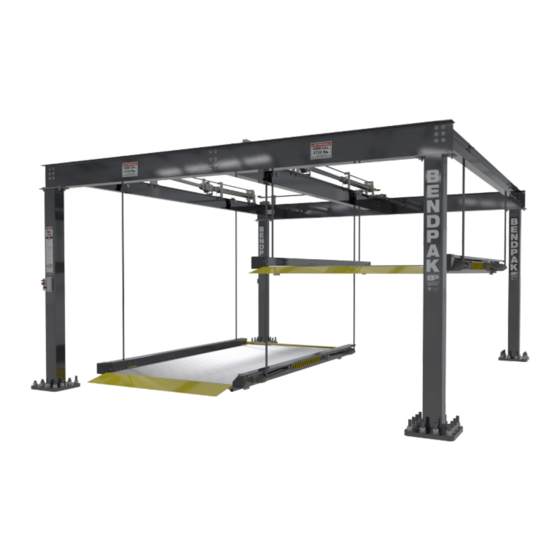
Double- and Triple-Wide Parking Lifts
Installation and Operation Manual
Manual P/N 5900056 — Manual Revision C2 — June 2019
Models:
• PL-6KDT
• PL-6KDTX
• PL-6KT
• PL-6KDT-S
• PL-6KDTX-S
• PL-6KT-S
Designed and engineered by BendPak Inc. in Southern California, USA. Made in China.
⚠
DANGER
entire
contents of this Manual
Read the
product. Failure to follow the instructions and safety precautions in
this Manual can result in serious injury or death. Make sure all other
operators also read this Manual. Keep the Manual near the product
for future reference. By proceeding with setup and operation, you
agree that you fully understand the contents of this Manual.
1645 Lemonwood Dr.
Santa Paula, CA 93060 USA
Toll Free: (800) 253-2363
Tel: (805) 933-9970
bendpak.com
Model PL-6KDT-S shown.
before
using this
Advertisement
Table of Contents

Subscribe to Our Youtube Channel
Related Manuals for BendPak PL-6KDT-S


Summary of Contents for BendPak PL-6KDT-S
- Page 1 • PL-6KDT • PL-6KDTX • PL-6KT • PL-6KDT-S • PL-6KDTX-S • PL-6KT-S Model PL-6KDT-S shown. Designed and engineered by BendPak Inc. in Southern California, USA. Made in China. ⚠ entire contents of this Manual before using this Read the product. Failure to follow the instructions and safety precautions in DANGER this Manual can result in serious injury or death.
- Page 2 Copyright. Copyright © 2019 by BendPak Inc. All rights reserved. You may make copies of this document if you agree that: you will give full attribution to BendPak Inc., you will not make changes to the content, you do not gain any rights to this content, and you will not use the copies for commercial purposes.
-
Page 3: Table Of Contents
So if you see “PL-6KDT” in text, it means “PL-6KDT and PL-6KDT-S”, and so on. More information about the full line of BendPak products can be found at bendpak.com. -
Page 4: Shipping Information
Keep this Manual on or near the product for future reference. Read and follow the warnings and instructions on the labels on the product. Contact BendPak at (800) 253-2363 or techsupport@bendpak.com... - Page 5 Make a visual inspection of the product before using it. Check for damaged, worn, or missing parts. Do not use the product if you find any of these issues. Instead, take the Lift out of service, then contact an authorized repair facility, your dealer, or BendPak at (800) 253-2363 or techsupport@bendpak.com.
-
Page 6: Components
Offside Posts. All four posts are part of the structure of the Lift. The Control Post and the Power Post have special functions, mentioned above; the Offside Posts are part of the structure. Model PL-6KDT-S shown; the PL-6KDTX is wider and the PL-6KT has a third Platform and a second Center Crossbeam. Standard models have different base plates. -
Page 7: Faqs
Cover the Power Unit ( ), put a canopy over the Lift, keep it clean and dry, and increase maintenance. Contact BendPak Customer Service (web bendpak.com/support, email phone (800) 253-2363) for additional information. techsupport@bendpak.com, Q: Can I use my Lift to store boxes of stuff instead of a Vehicle? A: No. -
Page 8: Will My Car Fit
Will My Car Fit? Your Lift accommodates a wide variety of cars, light trucks, and SUVs. Width Considerations for Vehicle width include: • Platform width. The usable width of the Platform is 86 inches (7.1 feet, 2184 mm); your tires All four tires must be fully on the Platform cannot be wider than this. -
Page 9: Safety Lock Positions
Safety Lock Positions Each Platform can be set to a High or Low Safety Lock position. Each Platform is set independently of the other Platform(s) on the Lift. The two settings are: more room under • High setting: Moves the Platform higher, leaving the Platform (and thus less room above the Platform) when it is on its Safety Lock. -
Page 10: Specifications
Specifications Model PL-6KDT Platforms 2 Platforms Lifting capacity per Platform 6,000 lbs / 2,722 kg 210.7" (17.5 feet) / 5,352 mm Total width 236.5" (19.7 feet) / 6,008 mm Total depth 103.3" (8.6 feet) / 2,625 mm Post height 123.6" (10.3 feet) / 3,140 mm Total height 4.5"... - Page 11 Model PL-6KDTX Platforms 2 Platforms Lifting capacity per Platform 6,000 lbs / 2,722 kg 250" (20.8 feet) / 6,350 mm Total width 236.5" (19.7 feet) / 6,008 mm Total depth 103.3" (8.6 feet) / 2,625 mm Post height 123.6" (10.3 feet) / 3,140 mm Total height 4.5"...
- Page 12 Model PL-6KT Platforms 3 Platforms Lifting capacity per platform 6,000 lbs / 2,722 kg 308.4" (25.7 feet) / 7,834 mm Total width 236.5" (19.7 feet) / 6,008 mm Total depth 103.3" (8.6 feet) / 2,625 mm Post height 123.6" (10.3 feet) / 3,140 mm Total height 4.5"...
-
Page 13: Orientation
Orientation opposite The Front of your Lift, as with many Lifts, is the end the Ramps. In the case of the PL-6K Series, the Power Unit and Power Post are at the Front, while the Ramps, the Control Post, and the Control Box are at the Rear. Drawing not necessarily to scale. -
Page 14: Installation Checklist
Installation Checklist Following are the steps needed to install a PL-6K Series Lift. Perform them in the order shown. ☐ 1. Review the installation Safety rules. ☐ 2. Make sure you have the necessary Tools. ☐ 3. Plan for electrical work. ☐... -
Page 15: Installation
. If you use parts from a different source, you void your Warranty and compromise the safety of everyone who installs or uses the Lift. If you are missing parts, visit bendpak.com/support or call (800) 253-2363, extension 191. Safety While installing this equipment, your safety depends on proper training and thoughtful operation. - Page 16 • Outdoor installations. PL-6K Series Lifts are not designed to be installed outdoors. installation is prohibited . If you are still considering installing your Lift outdoors, contact BendPak Customer Service ( email techsupport@bendpak.com, bendpak.com/support, phone (800) 253-2363). • Floor. Only install the Lift on a flat, concrete floor; do not install on asphalt or any other surface.
- Page 17 ⚠ CAUTION BendPak Lifts are supplied with installation instructions and concrete anchors that met the criteria set by the American National Standard “Automotive Lifts – Safety Requirements for Construction, Testing, and Validation”, ANSI/ALI ALCTV-2011. You are responsible for any special regional structural and/or seismic anchoring requirements specified by any other agencies and/or codes such as the Uniform Building Code (UBC) and/or International Building Code (IBC).
- Page 18 To create the four Chalk Line Guides: 1. Create the Front Chalk Line where you want the Front of the Lift. Make the Front Chalk Line longer than the Total Width setting for your Lift model. 2. Create the Powerside and Offside Chalk Lines at 90° angles to the Front Chalk Line and parallel to each other.
- Page 19 Move the Posts into Position BendPak strongly recommends using a Forklift or Crane to move the Posts. You need to have at least three people work together to stand up the Posts. ⚠ DANGER very The Posts are extremely heavy; be careful when handling them.
- Page 20 Choose the method that is best for your particular installation. BendPak recommends putting the Beams/Crossbeams on a raised platform, like sawhorses, when preparing the Beams/Crossbeams, no matter which method you choose. This generally makes them easier to prepare, compared to if they were on the ground.
- Page 21 Set Up and Install the Front Beam Set up and install the Front Beam first. To set up the Front Beam, you need to install the Sheaves on top. To set up and install the Front Beam: 1. Using a Forklift or Crane, put the Front Beam onto a heavy-duty rolling dolly and move it, on the ground, into location between the two Posts at the Front of the Lift.
- Page 22 Install the Rear Beam Install the Rear Beam after installing the Front Beam. There are no components that go on top of the Rear Beam; you simply need to raise it into position and put the bolts in place. Make sure the orientation is correct ;...
- Page 23 Prepare and Install the Offside Crossbeam Prepare and install the Offside Crossbeam after installing the Rear Beam. Before you can raise the Offside Crossbeam into place, you must prepare it by adding two Sheaves. Note: Unlike the Sheaves on the top of the Front Beam, the Sheaves in the crossbeams do not come installed;...
- Page 24 Prepare the Center Crossbeam(s) The PL-6KDT and the PL-6KDTX each have one Center Crossbeam. The PL-6KT has Center Crossbeams, so you will be preparing and installing two Center Crossbeams. The process is the same for the second Center Crossbeam. Center Crossbeams are taller than the other Crossbeams. Note: The following drawing shows the Center Crossbeam and its components.
- Page 25 To install components on a Center Crossbeam: 1. Using a Forklift or Crane, put the Center Crossbeam onto a heavy-duty rolling dolly and move it, on the ground, into location between the Front Beam and the Rear Beam. Make sure to orient the Center Crossbeam correctly. This drawing shows a Center Crossbeam from above.
- Page 26 2. Locate the Cylinder Mount, then take four nuts and bolts and connect it to the Center Crossbeam. 3. Locate the Cylinder Support, then take four more nuts and bolts and connect it to the Center Crossbeam. 4. Locate the Cylinder Sheave Mount Weldment and move it into position. The Cylinder Sheave Mount Weldment does not get connected to the Center Crossbeam.
- Page 27 10. Locate the Safety Latch Bar and attach one end to the circular end of the Cylinder Sheave Mount Weldment using a cotter pin. 11. Put the other end of the Safety Latch Bar through the inside of the Cylinder Guide Rod Support and rest it on the end of the Safety Bar.
- Page 28 It is not to scale. It includes both side and top views. Use for Cable routing only. ⚠ CAUTION BendPak strongly recommends wearing leather gloves specifically designed for Cable handling while you are routing the Cables. PL-6K Series of Parking Lifts...
- Page 29 1. Take one long Cable (90 feet / 27,584 mm) and one short Cable (60 feet / 18,085 mm) and stretch them out on the ground. BendPak recommends taping off the ends of the Cables; if they fray, they are much harder to route and more likely to cut your hands.
- Page 30 6. Once each section is through the Cylinder Mount, route them to 1 and 2 on the Cylinder Sheave Mount Assembly, going over the top of the Sheave and then down under the Sheave, on the way back towards the Cylinder Mount. Make sure cables 1 and 2, on their way back towards the Front Beam, are routed on the inside of the vertical piece under the Cylinder Sheave Mount Assembly and inside the rounded bar on the bottom of the Cylinder Support.
- Page 31 12. Before getting to the Cylinder Mount, route them to the double Sheave on the Offside Platform side of the Center Crossbeam: • Route A over the Sheave closest to the Center Crossbeam and then down. • Route B over the Sheave furthest from the Center Crossbeam and then over to the single Sheave near the Rear Beam.
- Page 32 Prepare the Powerside Crossbeam The components on the top of the Powerside Crossbeam are exactly the same as the components on the top of the Center Crossbeam(s). Because they are exactly the same, simply repeat the same process for the Powerside Crossbeam as you performed for the Center Crossbeam(s).
- Page 33 Routing the Cables on the Powerside Crossbeam Routing the Cables on the Powerside Crossbeam is almost exactly the same as routing the Cables on the Center Crossbeam(s); the Sheave locations on the Front Beam are the only differences. Because they are almost exactly the same, simply repeat the same process for the Powerside Crossbeam as you performed for the Center Crossbeam(s), noting the slightly different Sheave locations shown below.
- Page 34 Raise the Powerside Crossbeam into Position This procedure assumes the Powerside Crossbeam has all components in place, including as much Cable routing as can be done to this point. To raise the Powerside Crossbeam into position and secure it: 1. Raise the Powerside Crossbeam into the space between the Front Beam and the Rear Beam. 2.
- Page 35 There are multiple locations on the Power Unit Back Plate you can use to attach to the Mount Plate. Choose the ones that best center the Power Unit on the Mount Plate. The Power Unit is heavy. BendPak recommends having one person hold the Power Unit while another person bolts it into place.
- Page 36 3. Connect the Power Unit to the Power Post using the four nuts and bolts. 4. Fill the Hydraulic Reservoir on the Power Unit with approved fluids. The Hydraulic Reservoir holds approximately 3.7 gallons (14 litres). Use care to keep the fluid clean when filling the reservoir.
- Page 37 Install and Connect the Hydraulic System The Hydraulic System moves hydraulic force from the Power Unit to the Hydraulic Cylinders, which use that force to raise and lower the Platforms. The Hydraulic System includes: • Power Unit. Creates the hydraulic force that needs to be moved to the Hydraulic Cylinders. •...
- Page 38 To connect the Hydraulic System: 1. Locate the components for the Solenoid Valve Block Assembly, shown in the following drawing. Drawing not to scale. Components that are not part of the Solenoid Valve Block Assembly (Hydraulic Hose and Cylinder) shown to enhance understanding. 2.
- Page 39 Controls All wiring for the Controls must be minimum of #16 AWG (note that local codes may require heavier gauge). BendPak recommends encasing all wiring to protect it from the elements and anchoring it so that it stays in place.
- Page 40 Connect the Power Source The Power Unit must be connected to an appropriate power source. The standard Power Unit for your Lift is 220 VAC, 50/60 Hz, single phase. Refer to Wiring Diagrams for wiring information. ⚠ must DANGER All wiring be performed by a licensed, certified Electrician.
- Page 41 BendPak strongly recommends that you install a Power Disconnect Switch that is properly rated for the incoming power supply. ⚠...
- Page 42 Connect the Controls The Controls allow the operator of the Lift to select the desired Platform and then raise and lower it. Refer to Wiring Diagrams and the drawing on the next page for additional wiring information. ⚠ must DANGER All wiring be performed by a licensed, certified Electrician.
- Page 43 rewire the inside of the Electrical Box Note to Electrician: You need to based on the following drawing and the Wiring Diagrams. The following drawing shows a more detailed view of the PL-6 Series wiring. Drawing not to scale; not all components shown. Combines physical views and wiring views. PL-6K Series of Parking Lifts P/N 5900056 —...
- Page 44 Lift. All wires must be a minimum of #16 AWG (note that local codes may require heavier gauge). BendPak recommends encasing all wiring to protect it from the elements and anchoring it so that it stays in place.
- Page 45 Concrete or Anchor Bolts do not meet these specifications, it could lead to product damage, vehicle damage, personal injury, or even loss of life. BendPak Lifts are supplied with installation instructions and concrete fasteners meeting the criteria as prescribed by the American National Standard “Automotive Lifts – Safety Requirements for Construction, Testing, and Validation”...
- Page 46 ¾ inch diameter Anchor Bolt, for example, use a ¾ inch diameter drill bit. 3. Vacuum each hole clean. BendPak recommends using a vacuum to get the hole very clean. You can also use a wire brush, make sure to thoroughly clean each hole hand pump, or compressed air;...
- Page 47 Concrete. Assemble the Platform Structures Platform Structures support the Platform Sections, which together create a Platform. BendPak recommends assembling the Platform Structure, routing the Cables, and before testing the Platform putting on the Platform Sections. Adding the Platform Sections is described in a later section.
- Page 48 Note: The Side Pieces are interchangeable. Make sure you have one Left Side Piece and one Right Side Piece, and that they are oriented correctly. Drawing not necessarily to scale. Not all components shown. 3. Attach the Stop Bar in the desired location. There are two possible locations for the Stop Bar: between the Side Pieces at the front of the Platform or on top of the Side Pieces.
- Page 49 4. Attach the four Platform Cable Locks. The bolts/washers go on the inside, the nut on the outside. Do not torque the nuts yet. Drawing not necessarily to scale. Not all components shown. Side view shown. top two bolts only 5.
- Page 50 Put a small amount of white lithium grease or similar on those bushings prior to using the Lift. Operational Test before BendPak recommends doing an Operational Test of your Lift with a typical Vehicle starting normal usage (a Vehicle is not required, but is recommended).
- Page 51 To perform an Operational Test: 1. Check the area around and above the Lift for obstructions; move them if you find any. 2. If you are going to run the test with a typical Vehicle, drive it onto the desired Platform. 3.
-
Page 52: Operation
Check the Lift. Check the Lift for any missing, heavily worn, or damaged parts. Do not operate the Lift if you find any issues; instead, take it out of service, then contact your dealer, email techsupport@bendpak.com, or call (800) 253-2363. - Page 53 The Control Box controls your Lift: • The On/Off Switch is a security device; you must have the key in and turned to On to operate the Lift. • The Emergency Stop Button stops the Lift immediately when pressed. Use this if an unexpected and/or dangerous situation arises.
- Page 54 5. Release Up, then press and hold Down for two or three seconds to push the Safety Rod down into the Safety Lock Cavity. The Platform is now engaged on its Safety Lock. Note: If you do not release Up quickly enough, the Safety Rod will go past the Safety Lock Cavity, and you will not be able to engage the Platform on its Safety Lock.
-
Page 55: Maintenance
⚠ WARNING: Do not operate your Lift if you find maintenance issues; instead, take the Lift out of service, then contact your dealer, visit bendpak.com/support, email techsupport@bendpak.com, or call (800) 253-2363. PL-6K Series of Parking Lifts P/N 5900056 — Rev. C2 — June 2019... - Page 56 Wire Rope Inspection and Maintenance Your Lift’s wire rope should be inspected regularly: • Lifting Cables should be replaced when there are visible signs of damage or extreme wear. not use the Lift if it has damaged or worn cables; you must take it out of service! •...
-
Page 57: Troubleshooting
If the Lift is new, a break-in period may be needed; run the Lift several times each day. If the noises persist, contact BendPak Support. If you continue to have issues with your Lift, take it out of service, then contact your dealer, go to bendpak.com/support, email... - Page 58 Disposing of Hydraulic Fluid Hydraulic Fluid cannot be disposed of by dropping it into the trash or dumping it into the street. It has toxic ingredients that are harmful to the environment. Instead, you need to either recycle it or drop it off at a hazardous waste collection facility. First, note that there is a difference between dirty and contaminated Hydraulic Fluid: •...
-
Page 59: Wiring Diagrams
Wiring Diagrams PL-6KDT and PL-6KDTX Your Power Unit, when delivered, has different wiring for the control system. Your Electrician needs to rewire the Power Unit based on this drawing and other electrical information in this manual. PL-6K Series of Parking Lifts P/N 5900056 —... - Page 60 PL-6KT Your Power Unit, when delivered, has different wiring for the control system. Your Electrician needs to rewire the Power Unit based on this drawing and other electrical information in this manual. PL-6K Series of Parking Lifts P/N 5900056 — Rev. C2 — June 2019...
-
Page 61: Cable Routing Diagrams
Cable Routing Diagrams This section shows Cable routing diagrams for the Offside Platform. The Cable routing for Powerside Platforms and Center Platforms are virtually the same. PL-6K Series of Parking Lifts P/N 5900056 — Rev. C2 — June 2019... - Page 62 PL-6K Series of Parking Lifts P/N 5900056 — Rev. C2 — June 2019...
- Page 63 PL-6K Series of Parking Lifts P/N 5900056 — Rev. C2 — June 2019...
- Page 64 PL-6K Series of Parking Lifts P/N 5900056 — Rev. C2 — June 2019...
-
Page 65: Seismic Models
Seismic Models Models that end in –S are seismic models, which means they have enhanced holding strength in high- vibration environments and during earthquakes. The differences between standard and seismic models are: • Thicker bases on the bottoms of the Posts •... -
Page 66: Labels
Labels PL-6K Series of Parking Lifts P/N 5900056 — Rev. C2 — June 2019... - Page 67 PL-6K Series of Parking Lifts P/N 5900056 — Rev. C2 — June 2019...
-
Page 68: Parts Drawings
Parts Drawings PL-6K Series of Parking Lifts P/N 5900056 — Rev. C2 — June 2019... - Page 69 PL-6K Series of Parking Lifts P/N 5900056 — Rev. C2 — June 2019...
- Page 70 PL-6K Series of Parking Lifts P/N 5900056 — Rev. C2 — June 2019...
- Page 71 PL-6K Series of Parking Lifts P/N 5900056 — Rev. C2 — June 2019...
- Page 72 PL-6K Series of Parking Lifts P/N 5900056 — Rev. C2 — June 2019...
- Page 73 PL-6K Series of Parking Lifts P/N 5900056 — Rev. C2 — June 2019...
- Page 74 PL-6K Series of Parking Lifts P/N 5900056 — Rev. C2 — June 2019...
- Page 75 PL-6K Series of Parking Lifts P/N 5900056 — Rev. C2 — June 2019...
- Page 76 PL-6K Series of Parking Lifts P/N 5900056 — Rev. C2 — June 2019...
- Page 77 PL-6K Series of Parking Lifts P/N 5900056 — Rev. C2 — June 2019...
- Page 78 PL-6K Series of Parking Lifts P/N 5900056 — Rev. C2 — June 2019...
- Page 79 Automotive Lift Institute (ALI) Store You probably checked the ALI’s Directory of Certified Lifts (www.autolift.org/ali-directory-of- certified-lifts/) before making your most recent Lift purchase, but did you know the ALI Store (www.autolift.org/ali-store/) offers a wide variety of professional, easy-to-use, and reasonably priced training and safety materials that will make your garage a safer place to work? The ALI Store is your trusted source for workplace safety! Visit today and get the training and materials you need to work safely:...
- Page 80 1645 Lemonwood Drive Santa Paula, CA, 93060 USA © 2019 BendPak Inc. All rights reserved. bendpak.com...
Need help?
Do you have a question about the PL-6KDT-S and is the answer not in the manual?
Questions and answers