Table of Contents
Advertisement
Quick Links
Advertisement
Table of Contents

Related Manuals for THORLABS LTS150


Summary of Contents for THORLABS LTS150
- Page 1 LTS150 and LTS300 Long Travel Stages User Guide Original Instructions HA0203T...
-
Page 2: Table Of Contents
LTS Series Long Travel Stages Contents Chaper 1 Overview ..................... 1 1.1 Introduction ..................1 1.2 APT Software Overview ..............2 1.2.1 Introduction ..................... 2 1.2.2 APTUser Utility ..................3 1.2.3 APT Config Utility ..................4 1.2.4 APT Server (ActiveX Controls) ............... 5 1.2.5 Software Upgrades ................. - Page 3 Appendix B Specifications and Accessories ........... 45 Appendix C Motor Control Method Summary ........... 47 Appendix D Stepper Motor Operation ............51 Appendix E Regulatory ................57 Appendix F Thorlabs Worldwide Contacts ..........59 Page 0 Rev K Jan 2020...
-
Page 4: Chaper 1 Overview
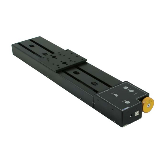
LTS Series Long Travel Stages Chapter 1 Overview 1.1 Introduction The LTS Series stages are a range of stepper-motor driven long travel stages with ranges of 150mm and 300mm. They have been designed to be light-weight, compact and robust with high perfomance over the full travel range. With a load capacity of up to 15 kg horizontally (4 kg vertically), these stages are highly suited to applications such as interferometry and M2 measurements and are compatible with our range of optomech and translation stages. -
Page 5: Apt Software Overview
Chapter 1 Overview 1.2 APT Software Overview 1.2.1 Introduction As a member of the APT range of controllers, the LTS series stages share many of the associated software benefits. This includes USB connectivity (allowing multiple units to be used together on a single PC), fully featured Graphical User Interface (GUI) panels, and extensive software function libraries for custom application development. -
Page 6: Aptuser Utility
LTS Series Long Travel Stages 1.2.2 APTUser Utility The APTUser application allows the user to interact with a number of APT hardware control units connected to the host PC. This program displays multiple graphical instrument panels to allow multiple APT units to be controlled simultaneously. All basic operating parameters can be altered and, similarly, all operations (such as motor moves) can be initiated. -
Page 7: Apt Config Utility
Chapter 1 Overview 1.2.3 APT Config Utility There are many system parameters and configuration settings associated with the operation of the APT Server. Most can be directly accessed using the various graphical panels, however there are several system wide settings that can be made 'off-line' before running the APT software. -
Page 8: Apt Server (Activex Controls)
Basic, Labview, Visual C++, C++ Builder, HPVEE, Matlab, VB.NET, C#.NET and, via VBA, Microsoft Office applications such as Excel and Word. Consider the ActiveX Control supplied for the LTS150 integrated stage & controller. This Control provides a complete user graphical instrument panel to allow the stage... -
Page 9: Software Upgrades
APT controller. This CD contains a complete range of tutorial samples and coding hints and tips, together with handbooks for all the APT controllers. 1.2.5 Software Upgrades Thorlabs operate a policy of continuous product development and may issue software upgrades as necessary. Page 6 Rev K Jan 2020... -
Page 10: Chaper 2 Safety
LTS Series Long Travel Stages Chapter 2 Safety 2.1 Safety Information For the continuing safety of the operators of this equipment, and the protection of the equipment itself, the operator should take note of the Warnings, Cautions and Notes throughout this handbook and, where visible, on the product itself. The following safety symbols may be used throughout the handbook and on the equipment itself. -
Page 11: Chaper 3 Mechanical Installation
Chapter 3 Mechanical Installation Chapter 3 Mechanical Installation Warning The safety of any system incorporating this equipment is the responsibility of the person performing the installation. 3.1 Unpacking Caution Once removed from its packaging, the LTS stage is easily damaged by mishandling. -
Page 12: Mounting To A Work Surface
If equipment mounted on the moving platform is driven against a solid object, damage to the internal mechanism could occur. The range of travel for each model is as follows: LTS150 - 150mm, LTS300 - 300mm. Page 9... -
Page 13: Mounting The Stage To The Work Surface
The LTS stage is mounted to the working surface by 1/4-20 (M6) screws (five for LTS300, three for LTS150), which fit through the base. The mounting holes are accessed from the top of the stage. Sleeves are fitted in the moving platform to allow the bolts to pass through from the top surface - see Fig. -
Page 14: Mounting In Multi-Axis Configurations
3.3.3 Mounting In Multi-Axis Configurations The LTS series stages can be mounted in XY configurations using the LTSP1 spacer plate. The LTSP2 and LTSP3 angle brackets allow the LTS150 and LTS300 stages respectively to be mounted vertically in Z axis configurations. -
Page 15: Calibration Of Motor Drives
Chapter 3 Mechanical Installation Caution Ensure that any devices and components attached to the moving platform are securely fastened. Incorrectly attached components could come loose when the stage is operated. 3.4 Calibration of Motor Drives Calibration enables the server to correct for any mechanical errors inherent in the system. -
Page 16: Chaper 4 Software & Electrical Installation
To minimize the possibility of this happening it is strongly recommended that any such modes that result in prolonged unresponsiveness be disabled before the APT software is run. Please consult your system administrator or contact Thorlabs technical support for more details. Caution Some PCs may have been configured to restrict the users ability to load software, and on these systems the software may not install/run. -
Page 17: Electrical Installation
Warning: Risk of Electrical Shock The PSU unit must be connected only to an earthed fused supply of 110 to 230V. Use only the power supply supplied by Thorlabs, other units may not be rated to the same current. The unit is shipped to the UK, Europe and the USA, with the appropriate power plug already fitted. -
Page 18: Verifying Software Operation
LTS Series Long Travel Stages 4.4 Verifying Software Operation 4.4.1 Initial Setup 1) Run the APTUser utility and check that the Graphical User Interface (GUI) panel appears and is active. Fig. 4.2 Gui panel showing jog and ident buttons 2) Check that the correct stage type and serial number are displayed in the GUI panel. -
Page 19: Chaper 5 Standalone Operation
Chapter 5 Standalone Operation Chapter 5 Standalone Operation 5.1 Introduction The LTS series of integrated long travel stages offer a fully featured motion control capability including velocity profile settings, limit switch handling and homing sequences. When the unit is connected to the PC, these parameters are automatically set to allow “out of the box”... -
Page 20: Control Keypad
LTS Series Long Travel Stages 5.2 Control Keypad LTS Long Travel Stage VELOCITY MOVE/JOG ACTIVE ENABLE Fig. 5.1 Front Panel Controls and Indicators MOVE Controls - These controls allow all motor moves to be initiated. Jog Buttons - Used to jog the motors and make discrete position increments in either direction - see Section 6.7. -
Page 21: Button Operation
Chapter 5 Standalone Operation 5.4 Button Operation The buttons on the front of the unit can be used to control the motor in a number of ways, as described below. 5.4.1 Homing A ‘Home’ move is performed to establish a datum from which subsequent absolute position moves can be measured (see Section 6.3. -
Page 22: Chaper 6 Pc Operation
Hardware configurations and parameter settings can be saved to a file, which simplifies system set up whenever APT User is run up. Fig. 6.1 Typical APT User Screen 1) Run the APT User program - Start/All Programs/Thorlabs/APT User/APT User. Page 19 16275-D02... -
Page 23: Homing Motors
Chapter 6 PC Operation 6.3 Homing Motors Homing the motor moves the actuator to the home limit switch and resets the internal position counter to zero. The limit switch provides a fixed datum that can be found after the system has been powered up. Fig. -
Page 24: Moving To An Absolute Position
LTS Series Long Travel Stages 6.4 Moving to an Absolute Position Absolute moves are measured in real world units (e.g. millimetres), relative to the Home position. 1) Click the position display. Fig. 6.3 Absolute Position Popup Window 2) Enter 3.0 into the pop up window 3) Click ‘OK’. -
Page 25: Changing Motor Parameters
Chapter 6 PC Operation 6.6 Changing Motor Parameters Moves are performed using a trapezoidal or S-Curve velocity profile (see Appendix D, Section D.1.3.). The velocity settings relate to the maximum velocity at which a move is performed, and the acceleration at which the motor speeds up from zero to maximum velocity. -
Page 26: Jogging
LTS Series Long Travel Stages 6.7 Jogging During PC operation, the motor actuators are jogged using the GUI panel arrow keys. There are two jogging modes available, ‘Single Step’ and ‘Continuous’. In ‘Single Step’ mode, the motor moves by the step size specified in the Step Distance parameter. -
Page 27: Graphical Control Of Motor Positions (Point And Move)
All units are displayed in real world units, i.e. millimetres. Note. For single channel units such as the LTS150, the Channel 2 parameters are greyed out. The left hand display shows a circle, which represents the current position of the stage associated with the ActiveX Control Instance (absolute position data is displayed in the 'Chan Pos' field). - Page 28 LTS Series Long Travel Stages Move Mode When ‘Move’ is selected, the motors move to an absolute position which corresponds to the position of the cursor within the screen. To specify a move: 1) Position the mouse within the window. For reference, the absolute motor position values associated with the mouse position is displayed in the 'Cursor Position field.
-
Page 29: Setting Move Sequences
Chapter 6 PC Operation 6.9 Setting Move Sequences This section explains how to set move sequences, allowing several positions to be visited without user intervention. For details on moving to absolute positions initiated by a mouse click – see Section 6.10. - Page 30 LTS Series Long Travel Stages 3) Select 'New' to display the 'Move Editor' panel. Fig. 6.9 Move Editor Window Move data is entered/displayed as follows: Dist/Pos: - the distance to move from the current position (if 'Relative' is selected) or the position to move to (if 'Absolute' is selected). Dwell Time: - after the move is performed, the system can be set to wait for a specified time before performing the next move in the sequence.
- Page 31 Chapter 6 PC Operation 4) Enter the required move data into the Move Editor and click OK. The move data is displayed in the main window as shown below. Fig. 6.10 Main Window with Move Data 5) Repeat step 4 as necessary to build a sequence of moves. Move data can be copied, deleted, cut/pasted and edited by right clicking the data line(s) and selecting the appropriate option in the pop up menu (shown below).
-
Page 32: Creating A Simulated Configuration Using Apt Config
To create a simulated configuration proceed as follows: 1) Run the APT Config utility - Start/All Programs/Thorlabs/APT/APT Config. 2) Click the 'Simulator Configuration' tab. Fig. 6.13 APT Configuration Utility - Simulator Configuration Tab 3) Enter ‘LAB1’... - Page 33 4) In the 'Simulator' field, check the ‘Enable Simulator Mode’ box. The name of the most recently used configuration file is displayed in the 'Current Configuration' window. 5) In the ‘Control Unit’ field, select the appropriate LTS stage ’LTS300’ or LTS150’. Page 30 Rev K Jan 2020...
- Page 34 LTS Series Long Travel Stages 6) Enter a 6 digit serial number. Note Each physical APT hardware unit is factory programmed with a unique 8 digit serial number. In order to simulate a set of ‘real’ hardware the Config utility allows an 8 digit serial number to be associated with each simulated unit.
-
Page 35: Chaper 7 Software Reference
Chapter 7 Software Reference Chapter 7 Software Reference 7.1 Introduction This chapter gives an explanation of the parameters and settings accessed from the APT software running on a PC. 7.2 GUI Panel The following screen shot shows the graphical user interface (GUI) displayed when accessing the stepper controller using the APTUser utility. - Page 36 LTS Series Long Travel Stages Moving - lit when the motor is in motion. Enable - applies power to the motor. With the motor enabled, the associated Channel LED on the front panel is lit. Digital display - shows the position (in millimetres) of the motor. The motor must be 'Homed' before the display will show a valid position value, (i.e.
-
Page 37: Settings Panel
Chapter 7 Software Reference 7.3 Settings Panel When the 'Settings' button on the GUI panel is clicked, the 'Settings' window is displayed. This panel allows motor operation parameters such as move/jog velocities, and stage/axis information to be modified. Note that all of these parameters have programmable equivalents accessible through the ActiveX methods and properties on this Control (refer to the Programming Guide in the APTServer helpfile for further details and to Section 1.2.4. - Page 38 LTS Series Long Travel Stages Note The max velocity and acceleration values quoted opposite are achievable with lighter loads. As the load is increased, the velocity and acceleration should be decreased accordingly. For the maximum 15 kg load, the velocity should be reduced to either 15 mm/s with 3 mm/s acceleration or 12 mm/sec with 5 mm/s acceleration, depending upon whether speed or acceleration is more important for...
- Page 39 Chapter 7 Software Reference Single Step - the motor moves by the step size specified in the Step Distance parameter. Continuous - the motor continues to move until the jog signal is removed (i.e. jog button is released). Stopping - the way in which the jog motion stops when the demand is removed. Immediate - the motor stops quickly, in a non-profiled manner Profiled - the motor stops in a profiled manner using the jog Velocity Profile parameters set above.
- Page 40 LTS Series Long Travel Stages is decelerated at ‘a’ so that the final position is approached slowly in a controlled manner. velocity maximum velocity (v) acceleration (slope) a time Fig. 7.4 Graph of a trapezoidal velocity profile The S-curve profile is a trapezoidal curve with an additional 'Bow Value' parameter, which limits the rate of change of acceleration and smooths out the contours of the motion profile.
- Page 41 Chapter 7 Software Reference manner to the acceleration phase, using the Bow Index to reach the maximum deceleration (D) and then bring the axis to a stop at the destination. Note The higher the Bow Index, then the shorter the BI phases of the curve, and the steeper the acceleration and deceleration phases.
-
Page 42: Stage/Axis Tab
LTS Series Long Travel Stages 7.3.2 Stage/Axis tab Fig. 7.6 Stepper Motor Controller - Stage/Axis Settings Note This tab contains a number of parameters which are related to the physical characteristics of the particular stage associated with the GUI panel. They need to be set accordingly such that the stage is driven properly by the system. - Page 43 Chapter 7 Software Reference Homing When homing, a stage typically moves in the reverse direction, (i.e. towards the reverse limit switch). The following settings allow support for stages with both Forward and Reverse limits. Note Typically, the following two parameters are set the same, i.e. both Forward or both Reverse.
- Page 44 LTS Series Long Travel Stages Motor These parameters are used to set the 'resolution' characteristics of the stepper motor connected to the selected channel. The resolution of the motor, combined with other characteristics (such as lead screw pitch) of the associated actuator or stage, determines the overall resolution.
-
Page 45: Advanced Tab
Chapter 7 Software Reference 7.3.3 Advanced Tab Fig. 7.7 Advanced Settings Button Control Settings The buttons on the front of the unit can be used either to jog the motor, or to perform moves to absolute positions. Button Mode: This setting determines the type of move performed when the front panel buttons are pressed. - Page 46 LTS Series Long Travel Stages Potentiometer Control Settings The potentiometer slider is sprung such that when released it returns to it’s central position. In this central position the motor is stationary. As the slider is moved away from the centre, the motor begins to move. Velocity: The velocity of the move in real world units (mm).
-
Page 47: Appendix A Maintenance
In the event of a breakdown, or malfunction of the product please contact Thorlabs Tech Support. Contact details are contained in Chapter 6 . Page 44... -
Page 48: Appendix B Specifications And Accessories
LTS150 0.13 % LTS300 0.12 % Home Location Accuracy ±0.6 µm Pitch LTS150 0.016° LTS300 0.022° LTS150 0.05° LTS300 0.06° Construction Aluminum with precision, recirculating linear bearings Weight LTS150 1.9 kg (4.8 lb) LTS300 2.5 kg (5.5 lb) Page 45 16275-D02... - Page 49 Long Travel Stage with 150 mm travel LTS300 and LTS300/M Long Travel Stage with 300 mm travel LTSP1 and LTSP1/M XY Mounting Adapter Plate LTSP2 and LTSP2/M Vertical (Z-axis) Mounting Plate for LTS150 LTSP3 and LTSP3/M Vertical (Z-axis) Mounting Plate for LTS300 HA0203T Handbook Page 46...
-
Page 50: Appendix C Motor Control Method Summary
LTS Series Long Travel Stages Appendix C Motor Control Method Summary The 'Motor' ActiveX Control provides the functionality required for a client application to control one or more of the APT series of motor controller units. To specify the particular controller being addressed, every unit is factory programmed with a unique 8-digit serial number. - Page 51 Chapter 7 Software Reference GetHomeParams Gets the homing sequence parameters. GetHomeParams_HomeVel Gets the homing velocity parameter (returned by value). GetHomeParams_ZeroOffset Gets the homing zero offset parameter (returned by value). GetHWCommsOK Gets the hardware communications OK flag. GetHWLimSwitches Gets the limit switch configuration settings. GetJogMode Gets the jogging button operating modes.
- Page 52 LTS Series Long Travel Stages GetStageAxisInfo_MinPos Gets the stage minimum position (returned by value). GetStatusBits_Bits Gets the controller status bits encoded in 32 bit integer (returned by value). GetTriggerParams Gets the move triggering parameters. GetVelParamLimits Gets the maximum velocity profile parameter limits. GetVelParams Gets the velocity profile parameters.
- Page 53 Chapter 7 Software Reference SetEncPosControlParams Sets the encoder position control parameters for encoder equipped stages. SetEncPosCorrectParams Sets the encoder position correction parameters for encoder equipped stages. SetHomeParams Sets the homing sequence parameters. SetHWLimSwitches Sets the limit switch configuration settings. SetJogMode Sets the jogging button operating modes.
-
Page 54: Appendix D Stepper Motor Operation
D.1 How A Stepper Motor Works D.1.1 General Principle Thorlabs’ actuators use a stepper motor to drive a precision lead screw. Stepper motors operate using the principle of magnetic attraction and repulsion to convert digital pulses into mechanical shaft rotation. The amount of rotation achieved is directly proportional to the number of input pulses generated and the speed is proportional to the frequency of these pulses. - Page 55 Chapter 7 Software Reference D.1.2 Positive and Negative Moves Positive and negative are used to describe the direction of a move. A positive move means a move from a smaller absolute position to a larger one, a negative move means the opposite. In the case of a linear actuator, a positive move takes the platform of the stage further away from the motor.
- Page 56 LTS Series Long Travel Stages The S-curve profile is a trapezoidal curve with an additional 'Bow Value' parameter, which limits the rate of change of acceleration and smooths out the contours of the motion profile. The Bow Value is specified in mm/s and is derived from the Bow Index field as follows: The Bow Value is applied in mm/s...
- Page 57 Chapter 7 Software Reference D.2 Positioning a Stage D.2.1 General Whenever a command is received to move a stage, the movement is specified in motion units, (e.g. millimetres). This motion unit value is converted to microsteps before it is sent to the stage. If operating the unit by the front panel (local mode) this conversion is performed internally by the controller.
- Page 58 LTS Series Long Travel Stages Movement is allowed right through the switch position in either direction. Datum switch +ve limit switch -ve limit switch (or stop) Linear stage Rotary stage Fig. D.4 Stage limit switches D.2.4 Minimum and Maximum Positions These positions are dependent upon the stage or actuator to which the motors are fitted, and are defined as the minimum and maximum useful positions of the stage relative to the ‘Home’...
- Page 59 Chapter 7 Software Reference D.2.5 Power Saving The current needed to hold a motor in a fixed position is much smaller than the current needed to move it, and it is advantageous to reduce the current through a stationary motor in order to reduce heating. Although this heating does not harm the motor or stage, it is often undesirable because it can cause thermal movements through expansion of the metal of the stage.
-
Page 60: Appendix E Regulatory
LTS Series Long Travel Stages Appendix E Regulatory E.1 Declarations Of Conformity E.1.1 For Customers in Europe See Section E.2. E.1.2 For Customers In The USA This equipment has been tested and found to comply with the limits for a Class A digital device, persuant to part 15 of the FCC rules. - Page 61 Chapter 7 Software Reference E.2 CE Certificate Page 58 Rev K Jan 2020...
-
Page 62: Appendix F Thorlabs Worldwide Contacts
Waste treatment is your own responsibility. "End of life" units must be returned to Thorlabs or handed to a company specializing in waste recovery. Do not dispose of the unit in a litter bin or at a public waste disposal site. - Page 63 www.thorlabs.com...
Need help?
Do you have a question about the LTS150 and is the answer not in the manual?
Questions and answers