Table of Contents
Advertisement
Quick Links
Advertisement
Table of Contents

Related Manuals for THORLABS LTS Series


Summary of Contents for THORLABS LTS Series
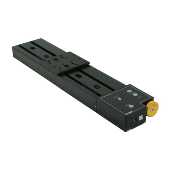
- Page 1 LTS150 and LTS300 Long Travel Stages User Guide Original Instructions HA0203T...
-
Page 2: Table Of Contents
LTS Series Long Travel Stages Contents Chaper 1 Overview ..................... 1 1.1 Introduction ..................1 1.2 Kinesis Software Overview ............... 1 1.2.1 Introduction ..................... 1 1.2.2 Kinesis Server ..................2 1.2.3 Software Upgrades ................. 3 Chaper 2 Safety ......................4 2.1 Safety Information ................ - Page 3 7.3.5 Advanced Tab ..................32 Appendices Appendix A Maintenance ................35 Appendix B Specifications and Accessories ........... 36 Appendix C Stepper Motor Operation ............38 Appendix D Regulatory ................44 Appendix E Thorlabs Worldwide Contacts ..........46 Page 0 Rev K Jan 2020...
-
Page 4: Chaper 1 Overview
1.2 Kinesis Software Overview 1.2.1 Introduction The LTS series stages share many of the benefits of the Thorlabs range of motor controllers. These include USB connectivity (allowing multiple units to be used together on a single PC), fully featured Graphical User Interface (GUI) panels, and extensive software function libraries for custom application development. -
Page 5: Kinesis Server
Chapter 1 Overview The Kinesis software suite provides a flexible and powerful PC based control system both for users of the equipment, and software programmers aiming to automate its operation. The User Interface allows full control of all settings and operating modes enabling complete ‘out-of-box’... -
Page 6: Software Upgrades
Kinesis Controls collection. This is available either by pressing the F1 key when running the Kinesis server, or via the Start menu, Start\Programs\Thorlabs\Kinesis\Kinesis Help. 1.2.3 Software Upgrades Thorlabs operate a policy of continuous product development and may issue software upgrades as necessary. Page 3 16275-D03... -
Page 7: Chaper 2 Safety
Chapter 2 Safety Chapter 2 Safety 2.1 Safety Information For the continuing safety of the operators of this equipment, and the protection of the equipment itself, the operator should take note of the Warnings, Cautions and Notes throughout this handbook and, where visible, on the product itself. The following safety symbols may be used throughout the handbook and on the equipment itself. -
Page 8: Chaper 3 Mechanical Installation
LTS Series Long Travel Stages Chapter 3 Mechanical Installation Warning The safety of any system incorporating this equipment is the responsibility of the person performing the installation. 3.1 Unpacking Caution Once removed from its packaging, the LTS stage is easily damaged by mishandling. -
Page 9: Mounting To A Work Surface
Chapter 3 Mechanical Installation 3.2 Mounting to a Work Surface Caution When siting the unit, it should be positioned so as not to impede the operation of the control panel buttons. Ensure that proper airflow is maintained to the unit. Caution Remove power from the unit before bolting or unbolting from the work surface. -
Page 10: Mounting The Stage To The Work Surface
LTS Series Long Travel Stages 3.2.2 Mounting the Stage to the Work Surface The LTS stage is mounted to the working surface by 1/4-20 (M6) screws (five for LTS300, three for LTS150), which fit through the base. The mounting holes are accessed from the top of the stage. -
Page 11: Mounting In Multi-Axis Configurations
Chapter 3 Mechanical Installation 3.2.3 Mounting In Multi-Axis Configurations The LTS series stages can be mounted in XY configurations using the LTSP1 spacer plate. The LTSP2 and LTSP3 angle brackets allow the LTS150 and LTS300 stages respectively to be mounted vertically in Z axis configurations. -
Page 12: Calibration Of Motor Drives
LTS Series Long Travel Stages Caution Ensure that any devices and components attached to the moving platform are securely fastened. Incorrectly attached components could come loose when the stage is operated. 3.3 Calibration of Motor Drives Calibration enables the server to correct for any mechanical errors inherent in the system. -
Page 13: Chaper 4 Software & Electrical Installation
The PSU unit must be connected only to an earthed fused supply of 110 to 230V. Use only the power supply supplied by Thorlabs, other units may not be rated to the same current. The unit is shipped to the UK, Europe and the USA, with the appropriate power plug already fitted. -
Page 14: Connecting The Hardware
LTS Series Long Travel Stages 4.3 Connecting The Hardware 1) Perform the mechanical installation as detailed in Section 3. 2) Install the Software - see Section 4.1. 3) Using the USB cable provided, connect the stage unit to your PC. -
Page 15: Verifying Software Operation
Chapter 4 Software & Electrical Installation 4.4 Verifying Software Operation 4.4.1 Initial Setup 1) Run the Kinesis softwareand check that the Graphical User Interface (GUI) panel appears and is active. Note If the Kinesis software does not recognise the unit, switch OFF the power but leave the kinesis software running and the USB connected. -
Page 16: Chaper 5 Standalone Operation
Chapter 5 Standalone Operation 5.1 Introduction The LTS series of integrated long travel stages offer a fully featured motion control capability including velocity profile settings, limit switch handling and homing sequences. When the unit is connected to the PC, these parameters are automatically set to allow “out of the box”... -
Page 17: Potentiometer Operation
Chapter 5 Standalone Operation 5.3 Potentiometer Operation The potentiometer slider is sprung such that when released it returns to it’s central position. In this central position the motor is stationary. As the slider is moved away from the centre, the motor begins to move. Bidirectional control of the motor is possible by moving the slider in both directions. -
Page 18: Stopping The Stage
LTS Series Long Travel Stages 5.5 Stopping the Stage The drive channel is enabled and disabled by clicking the ‘Enable’ button on the GUI panel or the top panel of the unit. The green indicator is lit when the drive channel is enabled. -
Page 19: Chaper 6 Pc Operation
Fig. 6.1 Typical User Screen 1) Run the Kinesis software - Start/All Programs/Thorlabs/Kinesis/Kinesis. Note If the Kinesis software does not recognise the unit, switch OFF the power but leave the kinesis software running and the USB connected. -
Page 20: Homing Motors
LTS Series Long Travel Stages 6.3 Homing Motors Homing the motor moves the actuator to the home limit switch and resets the internal position counter to zero. The limit switch provides a fixed datum that can be found after the system has been powered up. -
Page 21: Changing Motor Parameters And Moving To An Absolute Position
Chapter 6 PC Operation 6.4 Changing Motor Parameters and Moving to an Absolute Position Absolute moves are measured in real world units (e.g. millimetres), relative to the Home position. Moves are performed using a trapezoidal velocity profile (see Appendix C, Section C.1.3.). -
Page 22: Jogging
LTS Series Long Travel Stages 6.6 Jogging During PC operation, the motor actuators are jogged using the GUI panel arrow keys. There are two jogging modes available, ‘Single Step’ and ‘Continuous’. In ‘Single Step’ mode, the motor moves by the step size specified in the Step Distance parameter. -
Page 23: Setting Move Sequences
Chapter 6 PC Operation 6.7 Setting Move Sequences The Kinesis software allows move sequences to be programmed, allowing several positions to be visited without user intervention. For more details and instructions on setting move sequences, please see the Kinesis Helpfile. 6.8 Changing and Saving Parameter Settings During operation, certain settings (e.g. -
Page 24: Chaper 7 Software Reference
LTS Series Long Travel Stages Chapter 7 Software Reference 7.1 Introduction This chapter gives an explanation of the parameters and settings accessed from the Kinesis software running on a PC. 7.2 GUI Panel The following screen shot shows the graphical user interface (GUI) displayed when accessing the LTS controller using the Kinesis software. - Page 25 Chapter 7 Software Reference These settings can be adjusted as described previously, or by clicking the Settings button to display the settings window, see Section 7.3.2. Jog Controls - used to increment or decrement the motor position. The controls comprise a bar graph and a set of jog arrows.
-
Page 26: Keyboard Shortcuts
LTS Series Long Travel Stages Stop - halts the movement of the motor. Lower Display - Shows the present state of the motor, e.g. Idle, Moving, Moving EXT or Homing. Also shows the part number of the associated actuator or stage. -
Page 27: Settings Panel
Chapter 7 Software Reference 7.3 Settings Panel When the 'Settings' button on the GUI panel is clicked, the 'Settings' window is displayed. This panel allows motor operation parameters such as move/jog velocities, and stage/axis information to be modified. Note that all of these parameters have programmable equivalents (refer to the Kinesis Server helpfile for further details. -
Page 28: Moves/Jogs Tab
LTS Series Long Travel Stages 7.3.2 Moves/Jogs Tab Fig. 7.2 LTS Series Stage - Move/Jog Settings Display Units By default, the unit will display position in real world units (mm or degrees). If required, the units can be changed to so that the display shows other positional units (cm, µm, µrad etc). - Page 29 Chapter 7 Software Reference In ‘Continuous’ mode, the motor actuator will accelerate and move at the jog velocity while the button is held down.. Fig. 7.3 Jog Modes Jog - the motor moves by the distance specified in the Step Size parameter. Continuous - the motor continues to move until the jog signal is removed (i.e.
- Page 30 LTS Series Long Travel Stages Backlash Distance - The system compensates for lead screw backlash during reverse direction moves, by moving passed the demanded position by a specified amount, and then reversing. This ensures that positions are always approached in a forward direction.
- Page 31 Chapter 7 Software Reference motion profile. The Bow Value is applied in mm/s and is derived from the Bow Index field as follows: (Bow Index -1) Bow Value = 2 within the range 1 to 262144 (Bow Index 1 to 18). In this profile mode, the acceleration increases gradually from 0 to the specified acceleration value, then decreases at the same rate until it reaches 0 again at the specified velocity.
-
Page 32: Calibration Tab
This section is applicable only to NRT100, NRT150, LTS150, LTS300 and MLJ050 series stages, DRV013 and DRV014 actuators. Fig. 7.6 LTS Series Stage - Calibration Settings Calibration enables the server to correct for any mechanical errors inherent in the system. Mechanical components, such as the leadscrew and linkages, can be machined only within a certain tolerance, e.g. -
Page 33: Stage/Axis Tab
Chapter 7 Software Reference 7.3.4 Stage/Axis Tab Fig. 7.7 LTS Series Stage - Stage/Axis Settings Note This tab contains a number of parameters which are related to the physical characteristics of the particular stage being driven. They need to be set accordingly such that a particular stage is driven properly by the system. - Page 34 LTS Series Long Travel Stages Homing Settings When homing, a stage typically moves in the reverse direction, (i.e. towards the reverse limit switch). The following settings allow support for stages with both Forward and Reverse limits. Note Typically, the following two parameters are set the same, i.e. both Forward or both Reverse.
-
Page 35: Advanced Tab
Chapter 7 Software Reference 7.3.5 Advanced Tab Fig. 7.8 LTS Series Stages - Advanced Settings Potentiometer Settings The potentiometer slider is sprung such that when released it returns to it’s central position. In this central position the motor is stationary. As the slider is moved away from the centre, the motor begins to move. - Page 36 LTS Series Long Travel Stages The Resting Power is entered as a percentage of full power. Note The default values applied by the software have been selected based on the type of stage or actuator associated with the motor drive. Modify these values with caution (particularly the rest power) as the risk of damage to the motor due to overheating is significant.
-
Page 37: Appendix A Maintenance
In the event of a breakdown, or malfunction of the product please contact Thorlabs Tech Support. Contact details are contained in Chapter 5 . Page 34... -
Page 38: Appendix B Specifications And Accessories
LTS Series Long Travel Stages Appendix B Specifications and Accessories B.1 General Specifications Parameter Value Controller Specifications Microsteps per Full Step 2048 Microsteps per Revolution of Motor 409,600 (for 200 step motor) Motor Drive Voltage 24 V Motor Drive Power Up to 25 W (Peak)/ 12.5 W (Avg) - Page 39 Chapter 7 Software Reference B.2 Motor Specifications Parameter Value Step Angle 1.8° Step Accuracy Rated Phase Current 0.85 A Phase Resistance 5.4 Ohms Phase Inductance 5.6 mH Holding Torque 20 N.cm Detent Torque 2.0 N.cm Operating Temperature -20°C to +40°C (Motor Specification Only B.3 Parts List Part Number Description...
-
Page 40: Appendix C Stepper Motor Operation
C.1 How A Stepper Motor Works C.1.1 General Principle Thorlabs’ actuators use a stepper motor to drive a precision lead screw. Stepper motors operate using the principle of magnetic attraction and repulsion to convert digital pulses into mechanical shaft rotation. The amount of rotation achieved is directly proportional to the number of input pulses generated and the speed is proportional to the frequency of these pulses. - Page 41 Chapter 7 Software Reference C.1.2 Positive and Negative Moves Positive and negative are used to describe the direction of a move. A positive move means a move from a smaller absolute position to a larger one, a negative move means the opposite. In the case of a linear actuator, a positive move takes the platform of the stage further away from the motor.
- Page 42 LTS Series Long Travel Stages The S-curve profile is a trapezoidal curve with an additional 'Bow Value' parameter, which limits the rate of change of acceleration and smooths out the contours of the motion profile. The Bow Value is specified in mm/s...
- Page 43 Chapter 7 Software Reference C.2 Positioning a Stage C.2.1 General Whenever a command is received to move a stage, the movement is specified in motion units, (e.g. millimetres). This motion unit value is converted to microsteps before it is sent to the stage. If operating the unit by the front panel (local mode) this conversion is performed internally by the controller.
- Page 44 LTS Series Long Travel Stages Movement is allowed right through the switch position in either direction. Datum switch +ve limit switch -ve limit switch (or stop) Linear stage Rotary stage Fig. C.4 Stage limit switches C.2.4 Minimum and Maximum Positions...
- Page 45 Chapter 7 Software Reference C.2.5 Power Saving The current needed to hold a motor in a fixed position is much smaller than the current needed to move it, and it is advantageous to reduce the current through a stationary motor in order to reduce heating. Although this heating does not harm the motor or stage, it is often undesirable because it can cause thermal movements through expansion of the metal of the stage.
-
Page 46: Appendix D Regulatory
LTS Series Long Travel Stages Appendix D Regulatory D.1 Declarations Of Conformity D.1.1 For Customers in Europe See Section D.2. D.1.2 For Customers In The USA This equipment has been tested and found to comply with the limits for a Class A digital device, persuant to part 15 of the FCC rules. - Page 47 Chapter 7 Software Reference D.2 CE Certificate Page 44 Rev K Jan 2020...
-
Page 48: Appendix E Thorlabs Worldwide Contacts
Waste treatment is your own responsibility. "End of life" units must be returned to Thorlabs or handed to a company specializing in waste recovery. Do not dispose of the unit in a litter bin or at a public waste disposal site. - Page 49 www.thorlabs.com...
Need help?
Do you have a question about the LTS Series and is the answer not in the manual?
Questions and answers