Table of Contents
Advertisement
Quick Links
Important Information
Copyright
This publication, including all photographs, illustrations and software, is protected
under international copyright laws, with all rights reserved. Neither this manual, nor
any of the material contained herein, may be reproduced without the express written
consent of the manufacturer.
Disclaimer
The information in this document is subject to change without notice. The
manufacturer makes no representations or warranties with respect to the contents
hereof and specifically disclaims any implied warranties of merchantability or fitness
for any particular purpose. Further, the manufacturer reserves the right to revise this
publication and to make changes from time to time in the content hereof without
obligation of the manufacturer to notify any person of such revision or changes.
Trademark Recognition
Microsoft, MS-DOS and Windows are registered trademarks of Microsoft Corp.
MMX, Pentium, Pentium-II are a registered trademarks of Intel Corporation.
VGA, OS/2, PS/2 are registered trademarks of International Business Machines.
AMD, K5 are registered trademarks of Advanced Micro Devices Inc.
Cyrix, M1 are registered trademarks of Cyrix Corporation.
Other product names used in this manual are the properties of their respective owners
and are acknowledged.
Version 1.3
Advertisement
Table of Contents

Related Manuals for ECS P5SD-B Plus


Summary of Contents for ECS P5SD-B Plus
- Page 1 Important Information Copyright This publication, including all photographs, illustrations and software, is protected under international copyright laws, with all rights reserved. Neither this manual, nor any of the material contained herein, may be reproduced without the express written consent of the manufacturer. Disclaimer The information in this document is subject to change without notice.
- Page 2 Safety Compliance Federal Communications Commission (FCC) This equipment has been tested and found to comply with the limits for a Class B digital device, pursuant to Part 15 of the FCC Rules. These limits are designed to provide reasonable protection against harmful interference in a residential installation. This equipment generates, uses, and can radiate radio frequency energy and, if not installed and used in accordance with the instructions, may cause harmful interference to radio communications.
-
Page 3: Table Of Contents
Chapter 1: Introduction Welcome ..............1 About the Manual ............1 Checklist..............2 Features ..............2 Chapter 2: Installation Before You Begin . -
Page 4: Chapter 1: Introduction
Welcome Congratulations on your purchase of the P5SD-B+ mainboard. The P5SD-B+ mainboard is the latest generation of socket-7 motherboards with support for an accelerated graphics port AGP, a high-speed system bus, and onboard PCI IDE channels with UltraDMA-33 extensions. As a socket–7 board, the P5SD-B+ supports a wide range of Pentium MMX processors, the Pentium-compatible AMD K5/K6 series, the Cyrix/IBM 6X86, and the IDT C6 series CPUs. -
Page 5: Checklist
Software Use the Software Chapter to learn how to use the software drivers and support programs that are provided with this mainboard. Checklist Compare the contents of your mainboard package with the standard checklist below. If any item is missing or appears damaged, please contact the vendor of your mainboard package. - Page 6 AGP Graphics Support The mainboard has an AGP slot for the optional installation of an accelerated graphics port video adapter. AGP is today’s standard for high-performance 2D and 3D video processing Versatile Expansion Options The board has 6 expansion slots. Four PCI slots can be used by 32-bit PCI expansion cards.
-
Page 7: Chapter 2: Installation
Before You Begin Before you begin to install your P5SD-B+ mainboard, take some precautions to ensure that you avoid the possibility of damage to the product from static electricity. Ensure too that you are installing the mainboard into a suitable case. Static Electricity In adverse conditions, static electricity can accumulate and discharge through the integrated circuits and silicon chips on this product. -
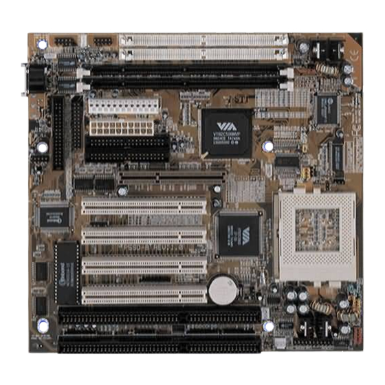
Page 8: Mainboard Guide
Mainboard Guide Use the following illustration and key to identify the components on your mainboard. COM2 JP100 COM1 SIM1 JP101 SIM2 DIMM1 DIMM2 JP13 FDD1 LPT1 JUSB1 IDE2 IDE1 JCH1 PCI1 JV_L1 PCI2 PCI3 JIR1 PCI4 SOCKET-7 JP12 JP11 JP10 JVBAT1 FAN2 JPW1... -
Page 9: Preparing The Mainboard
Component Description Connector for ATX power supply JIR1 Connector for infrared port JP100 Modem wake up connector JP101 LAN wake up connector Connector for PS/2 mouse FAN1 Power connector for CPU cooling fan FAN2 Power connector for system cooling fan JP 6,7,8 Speed setting for system bus, PCI bus, AGP bus jumpers Clock setting for memory jumper... - Page 10 5. If your processor includes a built-in cooling fan, connect the cable from the cooling fan to the CPU cooling fan connector on the mainboard FAN1. Install the Memory Modules On this mainboard, you can use 168-pin Dual In-line Memory Modules (DIMMs) or 72-pin Single In-Line Memory Modules (SIMMs).
- Page 11 Set the System Bus Speed, AGP and PCI clocks: JP6 to JP12 Jumpers JP6, JP7, JP8, JP9, JP10, JP11, and JP12 are used to set the mainboard timing for the system bus, the AGP clock, and the PCI clock. The table below shows the settings that are available.
- Page 12 Core Voltage Pins 1-2 Pins 3-4 Pins 5-6 Pins 7-8 2.8V Short Open Open Open 2.7V Open Short Short Short 2.6V Open Short Short Open 2.5V Open Short Open Short 2.4V Open Short Open Open 2.3V Open Open Short Short 2.2V Open Open...
-
Page 13: Install The Mainboard In The System Case
Clear CMOS Memory Jumper: JVBAT1 Locate the 3-pin Clear CMOS memory jumper JVBAT1. Ensure that the jumper cap is placed on pins 1-2. If you ever need to clear the system CMOS memory, you can do this by moving the jumper cap to short pins 2-3 for a few seconds. When you clear the CMOS memory, the system must be turned off and the power cord disconnected. - Page 14 Connect to COM1/2 Note: If you install and use both serial ports, you cannot use the infrared connector JIR1 to install an optional infrared port. 4. Connect the parallel port connector to the parallel port. The parallel port may be fixed on your system case, or it may be provided on a bracket like the serial port bracket shown above.
- Page 15 12. If you have installed a network adapter card, connect the adapter to the Wake On LAN connector JP101. 13. If you have installed an infrared port, connect the port to the Standard Infrared connector JIR1. Note: if you install and use an infrared port, you cannot use both of the serial ports COM1 and COM2 14.
-
Page 16: Chapter 3: Setup
About the Setup Utility This chapter explains how to use and modify the BIOS setup utility that is stored on the mainboard. The setup utility stores information about the mainboard components, and the configuration of other devices that are connected to it. The system uses this information to test and initialize components when it is started up, and to make sure everything runs properly when the system is operating. - Page 17 Some options lead to tables of items. These items usually have a value on the right side. The value of the first item is highlighted, and you can use the cursor arrow keys to select any of the other values in the table of items. When an item is highlighted, you can change the value by pressing the PageUp or PageDown keys, or the Plus or Minus keys.
-
Page 18: Standard Cmos Setup Option
Standard CMOS Setup Option This option displays a table of items which defines basic information about your system. Date and Time The Date and Time items show the current date and time held by your computer. If you are running a Windows operating system, these items will automatically be updated whenever you make changes to the Windows Date and Time Properties utility. -
Page 19: Bios Feature Setup Option
Floppy 3 Mode Support Default: Disabled Floppy 3 Mode is a special mode that supports 3.5” diskettes with a capacity of 1.2 MB. Outside of Japan, very few people use this kind of diskette. Video Default: EGA/VGA This item defines the video mode of the system. This mainboard has a built-in VGA graphics system so you must leave this item at the default value. - Page 20 External Cache Default: Enabled This mainboard is installed with 512K of external (level 2) cache memory to improve performance. Leave this item at the default value Enabled for better performance. Quick Power On Self Test Default: Enabled You can enable this item to shorten the power on testing and have your system start up a little faster.
-
Page 21: Chipset Features Option
Chipset Features Option This option displays a table of items that define critical timing parameters of the mainboard components including the CPU, the memory, and the system logic. As a general rule, you should leave the items on this page at their default values unless you are very familiar with the technical specifications of your system hardware. -
Page 22: Power Management Setup Option
Video BIOS Cacheable Default: Enabled System BIOS Cacheable Default: Enabled These two items allow the system and video BIOS to be cached for faster performance. We recommend that you leave these items at the default value Enabled. Memory Hole at 15M-16M Default: Disabled This item can be used to reserve memory space for some ISA cards that require it. - Page 23 Power Management Default: User Define This item acts like a master switch for the power-saving modes and hard disk timeouts. If this item is set to Disabled, all the power-saving modes are disabled. If this item is set to Max Saving, doze, standby, and suspend mode, will occur after a timeout of 20 seconds. If this item is set to Min Saving, doze, standby, and suspend mode will occur after a timeout of 40 minutes.
- Page 24 software power off. If the value is set to Delay 4 Sec. the power button must be held down for a full four seconds to cause a software power off. HDD Power Down Default: Disabled You can use this item to set a timeout for a hard disk powerdown. You can set a time from 1 to 15 minutes.
-
Page 25: Pnp/Pci Configuration Option
PNP/PCI Configuration Option This option displays a table of items that configures how PNP (Plug and Play) and PCI expansion cards operate in your system. If you have not installed a riser card with expansion slots, you do not need to make any changes to this option. PNP OS Installed Default: Yes If you have installed a Plug and Play operating system such as Windows 95 or 98, you can... -
Page 26: Load Bios Defaults Option
Assign IRQ for VGA Default: Enabled When this item is enabled, the system will assign an IRQ to the VGA system Load BIOS Defaults Option This option displays a dialog box which allows you to install BIOS defaults for all appropriate items in the whole setup utility. - Page 27 Onchip IDE First Channel Default: Enabled Onchip IDE Second Channel Default: Enabled You can use this item to enable or disable the primary and secondary IDE channels that are built into this mainboard. When one or both channels are enabled (the default value is Both) items appear which allow you to set the PIO (programmable input/output) mode and the UltraDMA mode for master and slave devices on the channels.
-
Page 28: Password Settings
UART 2 Mode Default: Standard This item defines the operation of serial port 2. In the default Standard setting, serial port 2 is assigned to the connector on the mainboard. If you have installed an optional infrared port, you must change the setting of this item to either HPSIR, or ASKIR. These settings will disable the mainboard serial port connector and assign serial port 2 to the infrared device. -
Page 29: Save And Exit Setup Option
using a very old drive that can’t be detected, you can install it manually using the Standard CMOS Setup option. Setup will check for two devices on the primary IDE channel and then two devices on the secondary IDE channel. At each device, the system will flash an N in the dialog box. -
Page 30: Chapter 4: Software
About the Software The support software for this mainboard may be supplied on a CD-ROM, or it may be supplied on a diskette or diskettes. All the support programs are stored in separate folders, so you can find the program you need easily enough. The support software contains the following programs: Power Management Patch (for WIN 95/98 only) Award Flash Memory Utility... - Page 31 Installing the VxD Driver The VxD driver provides support for an AGP graphics adapter. You only need to install this driver if you are running Windows 95, and you have installed the mainboard with an AGP graphics adapter. The VIA VxD driver is for use in Windows 95 version OSR 2.1 (4.00.950 B) or later. Windows 95 Installation You need the following files installed on your system before beginning the installation: 1.
- Page 32 This utility lets you erase the system BIOS that is stored on the system motherboard on a Flash Memory chip, and lets you write a new or updated BIOS onto the chip. Take care how you use this program. If you erase the current BIOS and fail to write a new BIOS, or write a new BIOS that is unsuitable, your system will malfunction.
-
Page 33: Quick Jumper Setting Reference
Quick Jumper Setting Reference Set the System Bus Speed, AGP and PCI clocks: JP6 to JP12 Speed Settings MHz Short Pin Settings JP10 JP11 JP12 95/90 Shaded row indicates the default values. Set the Memory Bus Speed: J9 and J10(CPU CLK:66MHz) J9 Function Jumper Cap DRAM run CPU CLK... - Page 34 Set Burst Mode: JCH1 Function Jumper Cap JCH1 Interleave Burst Short Pins 1-2 Linear Burst Short pins 2-3 Default Set for single voltage CPU or dual voltage CPU: JV_L1 Function Jumper Cap Example CPUs Single voltage CPU Open Pins 1-2 Intel P54C, IDT C6, AMD K5, IBM/Cyrix 6x86 Dual voltage CPU Short pins 1-2...
- Page 35 CPU Settings Internal Clock External Clock Clock Factor Intel Pentium CPUs (Including MMX) 100 MHz 66MHz x1.5 133MHz 66MHz x2.0 166MHz 66MHz x2.5 200MHz 66MHz x3.0 233MHz 66MHz x3.5 Cyrix/IBM CPUs 6X86 & 6X86L- P166+(133MHz) 66MHz x2.0 P200+(150MHz) 75MHz x2.0 6X86MX/MII- PR166(133MHz) 66MHz...
- Page 36 ŸP Rated CPUs Cyrix, IBM and AMD all make Pentium-class CPUs that are performace rated at an Intel Pentium equivalent speed but actually may have a slower internal clock speed. This ‘P’ rating is used to indicate the CPU’s performance rather than its internal clock speed.
Need help?
Do you have a question about the P5SD-B Plus and is the answer not in the manual?
Questions and answers