Table of Contents
Advertisement
Copyright
This publication, including all photographs, illustrations and software, is protected under
international copyright laws, with all rights reserved. Neither this manual, nor any of the
material contained herein, may be reproduced without written consent of the author.
Version 1.0
Disclaimer
The information in this document is subject to change without notice. The manufacturer
makes no representations or warranties with respect to the contents hereof and specifically
disclaims any implied warranties of merchantability or fitness for any particular purpose.
The manufacturer reserves the right to revise this publication and to make changes from
time to time in the content hereof without obligation of the manufacturer to notify any
person of such revision or changes.
Trademark Recognition
Microsoft, MS-DOS and Windows are registered trademarks of Microsoft Corp.
AMD, Athlon, and Duron are registered trademarks of AMD Corporation.
Other product names used in this manual are the properties of their respective owners and
are acknowledged.
Federal Communications Commission (FCC)
This equipment has been tested and found to comply with the limits for a Class B digital
device, pursuant to Part 15 of the FCC Rules. These limits are designed to provide reason-
able protection against harmful interference in a residential installation. This equipment
generates, uses, and can radiate radio frequency energy and, if not installed and used in
accordance with the instructions, may cause harmful interference to radio communications.
However, there is no guarantee that interference will not occur in a particular installation.
If this equipment does cause harmful interference to radio or television reception, which
can be determined by turning the equipment off and on, the user is encouraged to try to
correct the interference by one or more of the following measures:
•
Reorient or relocate the receiving antenna.
•
Increase the separation between the equipment and the receiver.
•
Connect the equipment onto an outlet on a circuit different from that to which
the receiver is connected.
•
Consult the dealer or an experienced radio/TV technician for help.
Shielded interconnect cables and a shielded AC power cable must be employed with this
equipment to ensure compliance with the pertinent RF emission limits governing this
device. Changes or modifications not expressly approved by the system's manufacturer
could void the user's authority to operate the equipment.
Preface
Preface
Advertisement
Table of Contents

Related Manuals for ECS PM800-M2


Summary of Contents for ECS PM800-M2
- Page 1 Preface Copyright This publication, including all photographs, illustrations and software, is protected under international copyright laws, with all rights reserved. Neither this manual, nor any of the material contained herein, may be reproduced without written consent of the author. Version 1.0 Disclaimer The information in this document is subject to change without notice.
- Page 2 Declaration of Conformity This device complies with part 15 of the FCC rules. Operation is subject to the following conditions: • This device may not cause harmful interference, and • This device must accept any interference received, including interference that may cause undesired operation. Canadian Department of Communications This class B digital apparatus meets all requirements of the Canadian Interference-causing Equipment Regulations.
-
Page 3: Table Of Contents
T T T T T ABLE OF CONTENTS ABLE OF CONTENTS ABLE OF CONTENTS ABLE OF CONTENTS ABLE OF CONTENTS Preface Chapter 1 Introducing the Motherboard Introduction....................1 Features.......................2 Motherboard Components...............4 Chapter 2 7 7 7 7 7 Installing the Motherboard Safety Precautions..................7 Choosing a Computer Case...............7 Installing the Motherboard in a Case............7... - Page 4 Integrated Peripherals..............35 Power Management Setup............39 PNP/PCI Configurations.............42 PC Health Status................43 Frequency/Voltage Control............43 Load Fail-Safe Defaults..............45 Load Optimized Defaults.............45 Set Supervisor/User Password............45 Save & Exit Setup Option.............46 Exit Without Saving..............46 Chapter 4 47 47 47 47 47 Using the Motherboard Software About the Software CD-ROM..............47 Auto-installing under Windows 98/ME/2000/XP........47 Running Setup................48...
-
Page 5: Introducing The Motherboard
Introduction Thank you for choosing PM800-M2 motherboard of great performance and with enhanced function. The PM800-M2 is designed to fit the advanced Intel Pentium 4 processors in the 478-pin package. Based on the Micro-ATX form factor, this motherboard incorporates the following chipsets: PM800 Northbridge and VT8237 Southbridge chipsets. -
Page 6: Features
Feature Processor PM800-M2 uses a 478-pin socket type of Pentium 4 that carries the following features: • Accommodates Intel Pentium 4 478-pin CPU • Supports a system bus (FSB) of 800/533/400 MHz • Intel P4 Celeron: FSB 400, 128K L2 cache •... - Page 7 Expansion Options The motherboard comes with the following expansion options: • Three 32-bit PCI slots • One AGP slot (support 1.5V only) • Two IDE headers which support four IDE devices • One floppy disk drive interface • Two 7-pin SATA connectors •...
-
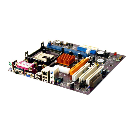
Page 8: Motherboard Components
Motherboard Components Introducing the Motherboard... - Page 9 Table of Motherboard Components LABEL COMPONENT 1 CPU Socket mPGA478 socket for Pentium 4 CPUs 2 DDR1~DDR2 184-pin DDR DIMM slots 3 CPUFAN1 CPU cooling fan connector 4 JP3 BIOS flash protect jumper 5 IDE1 Primary IDE connector 6 IDE2 Secondary IDE connector 7 FDD1 Floppy disk drive connector...
- Page 10 Memo Introducing the Motherboard...
-
Page 11: Installing The Motherboard
Make sure that your case supports all the features required. Secondly, PM800-M2 supports one or two floppy diskette drives and four enhanced IDE drives. Make sure that your case has sufficient power and space for all drives that you intend to install. -
Page 12: Checking Jumper Settings
Do not over-tighten the screws as this can stress the motherboard. Checking Jumper Settings This section explains how to set jumpers for correct configuration of the motherboard. Setting Jumpers Use the motherboard jumpers to set system configuration options. Jumpers with more than one pin are numbered. -
Page 13: Checking Jumper Settings
Checking Jumper Settings The following illustration shows the location of the motherboard jumpers. Pin 1 is labeled. Jumper Settings Jumper Type Setting (default) Description 3-pin CLEAR CMOS 1-2: NORMAL 2-3: CLEAR Before clearing the CMOS, make sure to turn the sys- tem off. -
Page 14: Connecting Case Components
Connecting Case Components After you have installed the motherboard into a case, you can begin con- necting the motherboard components. Refer to the following: Connect the CPU cooling fan cable to CPUFAN1. Connect the case cooling fan connector to CASFAN1. Connect the case speaker cable to SPK1. -
Page 15: Front Panel Connector
ATX2: ATX 12V Power Connector Signal Name Ground Ground +12V +12V Front Panel Connector The front panel connector (PANEL1) provides a standard set of switch and LED connec- tors commonly found on ATX or micro-ATX cases. Refer to the table below for informa- tion: Pin Signal Name Function... -
Page 16: Installing Hardware
Reset Switch Supporting the reset function requires connecting pin 5 and 7 to a momentary-contact switch that is normally open. When the switch is closed, the board resets and runs POST. Power Switch Supporting the power on/off function requires connecting pins 6 and 8 to a momentary- contact switch that is normally open. -
Page 17: Installing Memory Modules
CPU fan/heatsink supplied. The form and size of fan/heatsink may also vary. Installing Memory Modules PM800-M2 accommodates two 184-pin 2.5V unbuffered Double Data Rate (DDR) SDRAM (Synchronous Dynamic Random Access Memory) memory modules. PM800-M2 can support DDR400/DDR333/DDR266/DDR200 memory types. - Page 18 Installation Procedure Refer to the following to install the memory modules. This motherboard supports unbuffered DDR SDRAM only. Push the latches on each side of the DIMM slot down. Align the memory module with the slot. The DIMM slots are keyed with notches and the DIMMs are keyed with cutouts so that they can only be installed correctly.
- Page 19 Table A: DDR (memory module) QVL (Qualified Vendor List) The following DDR400 memory modules have been tested and qualified for use with this motherboard. Size Vendor Module Name SAMSUNG M368L1713DTM-CC4 128MB Micron MT8VDDT1664AG-403B2 NANYA NT128D64SH4B1G-5 Infineon HYS64D16301GU-5-B NANYA NT128D64SH4B1G-5T SAMSUNG M368L3223DTM-CC4 256MB NANYA...
-
Page 20: Installing A Hard Disk Drive/Cd-Rom/Sata Hard Drive
Installing a Hard Disk Drive/CD-ROM/SATA Hard Drive This section describes how to install IDE devices such as a hard disk drive and a CD-ROM drive. About IDE Devices Your motherboard has a primary and secondary IDE channel interface (IDE1 and IDE2). An IDE ribbon cable supporting two IDE devices is bundled with the motherboard. - Page 21 About SATA Connectors Your motherboard features two SATA connectors supporting a total of two drives. SATA refers to Serial ATA (Advanced Technology Attachment) is the standard interface for the IDE hard drives which are currently used in most PCs. These connectors are well designed and will only fit in one orientation.
-
Page 22: Installing A Floppy Diskette Drive
Installing a Floppy Diskette Drive The motherboard has a floppy diskette drive (FDD) interface and ships with a diskette drive ribbon cable that supports one or two floppy diskette drives. You can install a 5.25-inch drive and a 3.5-inch drive with various capacities. The floppy diskette drive cable has one type of connector for a 5.25-inch drive and another type of connector for a 3.5-inch drive. - Page 23 AGP specification. It is AGP 3.0 compliant. PCI Slot PM800-M2 is equipped with three standard PCI slots. PCI stands for Peripheral Component Interconnect and is a bus standard for expansion cards, which for the most part, is a supplement of the older ISA bus stan- dard.
-
Page 24: Connecting Optional Devices
Connecting Optional Devices Refer to the following for information on connecting the motherboard’s optional devices: SPDIFO1: SPDIF out header This is an optional header that provides an S/PDIF (Sony/Philips Digital Interface) output to digital multimedia device through optical fiber or coaxial connector. Signal Name Function SPDIF digital output... - Page 25 SATA1/SATA2: Serial ATA connectors These connectors are use to support the new Serial ATA devices for the highest date transfer rates (150 MB/s), simpler disk drive cabling and easier PC assembly. It eliminates limitations of the current Parallel ATA interface. But maintains register compatibility and software compatibility with Parallel ATA.
- Page 26 AUXIN1: Auxiliary In header This connector is an additional line-in audio connector. It allows you to attach a line-in cable when your rear line-in jack is set as line out port for 4-channel function. Signal Name Function AXU In left channel AUX_L Ground Ground...
-
Page 27: Connecting I/O Devices
Connecting I/O Devices The backplane of the motherboard has the following I/O ports: PS2 Mouse Use the upper PS/2 port to connect a PS/2 pointing device. PS2 Keyboard Use the lower PS/2 port to connect a PS/2 keyboard. Parallel Port (LPT1) Use LPT1 to connect printers or other parallel communications devices. - Page 28 Memo Installing the Motherboard...
-
Page 29: Using Bios
Chapter 3 Using BIOS About the Setup Utility The computer uses the latest Award BIOS with support for Windows Plug and Play. The CMOS chip on the motherboard contains the ROM setup instructions for configuring the motherboard BIOS. The BIOS (Basic Input and Output System) Setup Utility displays the system’s configura- tion status and provides you with options to set system parameters. - Page 30 Press DEL to enter SETUP Pressing the delete key accesses the BIOS Setup Utility: Phoenix-AwardBIOS CMOS Setup Utility: Standard CMOS Features Frequency/Voltage Control Advanced BIOS Features Load Fail-Safe Defaults Advanced Chipset Features Load Optimized Defaults Integrated Peripherals Set Supervisor Password Power Management Setup Set User Password PnP/PCI Configurations...
-
Page 31: Updating The Bios
Updating the BIOS You can download and install updated BIOS for this motherboard from the manufacturer’s Web site. New BIOS provides support for new peripherals, improvements in performance, or fixes for known bugs. Install new BIOS as follows: If your motherboard has a BIOS protection jumper, change the setting to allow BIOS flashing. -
Page 32: Standard Cmos Features
Standard CMOS Features This option displays basic information about your system. Phoenix-AwardBIOS CMOS Setup Utility Standard CMOS Features Date (mm:dd:yy) Tue, July 11 2003 Time (hh:mm:ss) 12:8:59 Item Help IDE Channel 0 Master [None] IDE Channel 0 Slave [None] IDE Channel 1 Master [None] Menu Level IDE Channel 1 Slave... - Page 33 IDE Channel 0/1 Master/Slave/Extended IDE Drive(Auto) Leave this item at Auto to enable the system to automatically detect and configure IDE devices on the channel. If it fails to find a device, change the value to Manual and then manually configure the drive by entering the characteristics of the drive in the items described below.
-
Page 34: Advanced Bios Features
Advanced BIOS Features This option defines advanced information about your system. Phoenix-AwardBIOS CMOS Setup Utility Advanced BIOS Features ATA66/100 IDE Cable Msg. [Enabled] Item Help Hard Disk Boot Priority [Press Enter] Quick Power On Self Test [Enabled] Menu Level First Boot Device [Floppy] Second Boot Device [Hard Disk]... - Page 35 First/Second/Third Boot Device (Floppy/Hard Disk/CDROM) Use these three items to select the priority and order of the devices that your system searches for an operating system at start-up time. Boot Other Device (Enabled) When enabled, the system searches all other possible locations for an operating system if it fails to find one in the devices specified under the First, Second, and Third boot devices.
-
Page 36: Advanced Chipset Features
Advanced Chipset Features These items define critical timing parameters of the motherboard. You should leave the items on this page at their default values unless you are very familiar with the technical specifications of your system hardware. If you change the values incorrectly, you may introduce fatal errors or recurring instability into your system. - Page 37 DRAM Timing (Auto By SPD) Set this to the default value to enable the system to automatically set the SDRAM timing by SPD (Serial Presence Detect). SPD is an EEPROM chip on the DIMM module that stores information about the memory chips it contains, including size, speed, voltage, row and column addresses, and manufacturer.
- Page 38 AGP & P2P Bridge Control (Press Enter) Scroll to this item and press <Enter> to view the following screen: Phoenix-AwardBIOS CMOS Setup Utility AGP & P2P Bridge Control AGP Aperture Size [128M] Item Help AGP 2.0 Mode [4X] AGP Driving Control [Auto] Menu Level AGP Driving Value...
-
Page 39: Integrated Peripherals
CPU & PCI Bus Control (Press Enter) Scroll to this item and press <Enter> to view the following screen: Phoenix-AwardBIOS CMOS Setup Utility CPU & PCI Bus Control PCI Delay Transaction [Disabled] Item Help Menu Level "#$% : Move Enter: Select +/-/PU/PD:Value F10:Save ESC:Exit F1: General Help F5:Previous Values F6:Fail-Safe Defaults... - Page 40 ! VIA OnChip IDE Device (Press Enter) Scroll to this item and press <Enter> to view the following screen: Phoenix-AwardBIOS CMOS Setup Utility VIA OnChip IDE Device OnChip SATA [Enabled] Item Help SATA Mode [IDE] IDE DMA transfer access [Enabled] Menu Level OnChip IDE Channel0 [Enabled]...
- Page 41 IDE HDD Block Mode (Enabled) Enable this field if your IDE hard drive supports block mode. Block mode enables BIOS to automatically detect the optimal number of block read and writes per sector that the drive can support and improves the speed of access to IDE devices. Press <Esc>...
- Page 42 USB Mouse Support (Enabled) Enables this item if you plan to use a mouse connected through the USB port in a legacy operating system (such as DOS) that does not support Plug and Play. Press <Esc> to return to the Integrated Peripherals page. ! SuperIO Device (Press Enter) Scroll to this item and press <Enter>...
-
Page 43: Power Management Setup
Power Management Setup This option lets you control system power management. The system has various power- saving modes including powering down the hard disk, turning off the video, suspending to RAM, and software power down that allows the system to be automatically resumed by certain events. - Page 44 Soft-Off by PWRBTN (Instant-Off) Under ACPI (Advanced Configuration and Power management Interface) you can create a software power down. In a software power down, the system can be resumed by Wake Up Alarms. This item lets you install a software power down that is controlled by the power button on your system.
- Page 45 Modem Ring Resume (Disabled) Use this item to enable modem activity to wakeup the system from a power saving mode. RTC Alarm Resume (Disabled) When set to Enabled, additional fields become available and you can set the date (day of the month), hour, minute and second to turn on your system.
-
Page 46: Pnp/Pci Configurations
PNP/PCI Configurations These options configure how PnP (Plug and Play) and PCI expansion cards operate in your system. Both the ISA and PCI buses on the Motherboard use system IRQs (Interrupt ReQuests) and DMAs (Direct Memory Access). You must set up the IRQ and DMA assign- ments correctly through the PnP/PCI Configurations Setup utility for the motherboard to work properly. -
Page 47: Pc Health Status
PC Health Status On motherboards that support hardware monitoring, this item lets you monitor the param- eters for critical voltages, critical temperatures, and fan speeds. Phoenix-AwardBIOS CMOS Setup Utility PC Health Status Item Help Shutdown Temperature [Disabled] CPU Vcore 1.68V 2.50 V 2.51V Menu Level... - Page 48 CPU Clock Ratio (10X) Enables you to set the CPU clock. The CPU clock ratio times the CPU Host/PCI Clock should equal the core speed of the installed processor. (For unlock Ratio CPU only.) Example: CPU Clock Ratio CPU Host/PCI Clock X100 Installed CPU Clock Speed 1 GHz...
-
Page 49: Load Fail-Safe Defaults
Load Fail-Safe Defaults Option This option opens a dialog box that lets you install fail-safe defaults for all appropriate items in the Setup Utility: Press <Y> and then <Enter> to install the defaults. Press <N> and then <Enter> to not install the defaults. -
Page 50: Save & Exit Setup Option
Save & Exit Setup Option Highlight this item and press <Enter> to save the changes that you have made in the Setup Utility and exit the Setup Utility. When the Save and Exit dialog box appears, press <Y> to save and exit, or press <N> to return to the main menu: Exit Without Saving Highlight this item and press <Enter>... -
Page 51: Using The Motherboard Software
Chapter 4 Using the Motherboard Software About the Software CD-ROM The support software CD-ROM that is included in the motherboard package contains all the drivers and utility programs needed to properly run the bundled products. Below you can find a brief description of each software program, and the location for your motherboard version. -
Page 52: Running Setup
Setup Tab Setup Click the Setup button to run the software installation program. Select from the menu which software you want to install. Browse CD The Browse CD button is the standard Windows command that allows you to open Windows Explorer and show the contents of the support Before installing the software from Windows Explorer, look for a file named README.TXT, INSTALL.TXT or something similar. - Page 53 The motherboard identification is located in the upper left-hand corner. Click Next. The following screen appears: Check the box next to the items you want to install. The default options are recommended. Click Next run the Installation Wizard. An item installation screen appears: Follow the instructions on the screen to install the items.
-
Page 54: Manual Installation
Manual Installation Insert the CD in the CD-ROM drive and locate the PATH.DOC file in the root directory. This file contains the information needed to locate the drivers for your motherboard. Look for the chipset and motherboard model; then browse to the directory and path to begin installing the drivers. -
Page 55: Via Vt8237 Sata Raid Setup Guide
Chapter 5 VIA VT8237 SATA RAID Setup Guide VIA RAID Configurations The motherboard includes a high performance Serial ATA RAID controller integrated in the VIA VT8237 Southbridge chipset. It supports RAID 0, RAID 1 and JBOD with two indepen- dent Serial ATA channels. RAID: (Redundant Array of Independent Disk Drives) use jointly several hard drives to increase data transfer rates and data security. - Page 56 Install the Serial ATA hard disks into the drive bays. Connect one end of the Serial ATA cable to the motherboard’s primary Serial ATA connector (SATA1). Connect the other end of Serial ATA cable to the master Serial ATA hard disk. Connect one end of the second Serial ATA cable to the motherboard’s sec- ondary Serial ATA connector (SATA2).
- Page 57 Create Array In the VIA RAID BIOS utility main menu, select Create Array then press the <Enter> key. The main menu items on the upper-left corner of the screen are replaced with create array menu options. RAID 0 for performance Select the second option item Array Mode, then press the <Enter>...
- Page 58 Select Start Create Process and press <Enter> to setup hard disk for RAID system. The following confirmation appears: The same confirmation message appears when the Auto Setup for Performance option is selected. Press “Y” to confirm or “N” to return to the configuration options. RAID 1 for data protection Select the second option item Array Mode, then press the <Enter>...
- Page 59 Delete Array In the VIA RAID BIOS utility main menu, select Delete Array then press the <Enter> key. The focus is directed to the list of channel used for IDE RAID arrays. Press the <Enter> key to select a RAID array to delete. The following confir- mation message appears.
- Page 60 Duplicate Critical RAID 1 Array When booting up the system, BIOS will detect if the RAID 1 array has any inconsistencies between user data and backup data. If BIOS detects any inconsistencies, the status of the disk array will be marked as critical, and BIOS will prompt the user to duplicate the RAID 1 in order to ensure the backup data consistency with the user data.
- Page 61 1. Power off and Check the Failed Drive: This item turns off the computer and replaces the failed hard drive with a good one. If your computer does not support APM, you must turn off your computer manually. After replacing the hard drive, boot into BIOS and select Choose replacement drive and rebuild to rebuild the broken array.
-
Page 62: Installing Raid Software & Drives
Windows XP installation. Existing Windows XP Driver Installation Insert the ECS CD into the CD-ROM drive. The CD will auto-run and the setup screen will appear. Under the Driver tab, click on VIA SATA RAID Utility. - Page 63 VIA SATA RAID utility • RAID0 and RAID1 functions Insert the ECS CD and click on the Setup to install the software. The InstallShield Wizard will begin automatically for installation. Click on the Next button to proceed the installation in the welcoming window.
-
Page 64: Using Via Raid Tool
Put a check mark in the check box to install the feature you want. Then click Next button to proceed the installation. Using VIA RAID Tool Once the installation is complete, go to Start---> Programs---> VIA---> raid_tool.exe to enable VIA RAID Tool. After the software is finished installation, it will automati- cally started every time Windows is initiated. - Page 65 The main interface is divided into two windows and the toolbar above contain the main functions. Click on these toolbar buttons to execute their specific functions. The left windowpane displays the controller and disk drives and the right windowpane displays the details of the controller or disk drives.
- Page 66 Click on the plus (+) symbol next to Array 0--RAID 0 to see the details of each disk. You may also use the same button to view the statuses of Array 0-- RAID 1. VIA VT8237 SATA RAID Setup Guide...
- Page 67 Click on the plus (+) symbol next to Array 0; RAID 1 to see the details of each disk. VIA VT8237 SATA RAID Setup Guide...
Need help?
Do you have a question about the PM800-M2 and is the answer not in the manual?
Questions and answers