Table of Contents
Advertisement
Quick Links
Advertisement
Table of Contents

Related Manuals for ECS P5SD-B


Summary of Contents for ECS P5SD-B
- Page 1 P5SD-B Mainboard User’s Manual...
- Page 2 P5SD-B User’s Manual Table Of Contents – II FCC & DOC Compliance FCC & DOC Compliance FCC & DOC Compliance FCC & DOC Compliance FCC & DOC Compliance Federal Communications Commission Statement Federal Communications Commission Statement Federal Communications Commission Statement...
-
Page 3: Table Of Contents
P5SD-B User’s Manual Table Of Contents – III 1: P5SD-B Package & Product Information .... 1.1 About This Manual ............... 1.1 Package Contents ............... 1.3 Mainboard Features ............1.4 Component Information ............. 1.6 Expansion Cards & Slots .............. 1.6 Memory Sockets & Modules ............1.7 CPU Socket &... - Page 4 IDE Transfer Modes ..............3.16 Installing IDE Devices..............3.18 Installing an AGP Card ............3.19 Adjusting The AGP Memory Aperture ......... 3.19 4: P5SD-B Reference Information ......4.1 Using This Section ............... 4.1 Jumper Configuration Summary ......... 4.3 Supported CPUs..............4.10 Interpreting CPU Markings ............
-
Page 5: 1: P5Sd-B Package & Product Information
Component Information 1: P5SD-B Package & Product Information This manual contains all the information you’ll need to use the P5SD-B mainboard. Please take a moment to familiarize your- self with the design and organization of the manual. About This Manual This manual is divided into four sections: •... - Page 6 P5SD-B User’s Manual 1: Package & Product Information – 1.2 The manual uses some icons to call your attention to impor- tant information. The icons appear in the sidebar and represent the following: • Important information • A recommendation or good idea •...
-
Page 7: Package Contents
P5SD-B User’s Manual 1: Package & Product Information – 1.3 Package Contents The P5SD-B mainboard package contains the following items. Please inspect the package contents and confirm that everything is there. If anything is missing or damaged, call your vendor for instructions before proceeding. -
Page 8: Mainboard Features
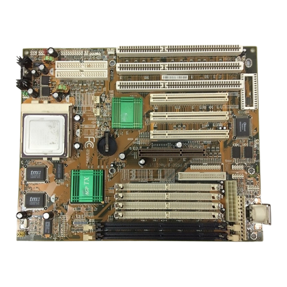
P5SD-B User’s Manual 1: Package & Product Information – 1.4 Mainboard Features This mainboard is a highly integrated Baby-AT design that incorporates many features on the board. The mainboard includes the following features: • Socket 7 CPU socket supports Pentium and compatible CPUs up to 266MHz •... - Page 9 P5SD-B User’s Manual 1: Package & Product Information – 1.5 P5SD-B Mainboard Layout PS/2 Keyboard Mouse USB Port AT Power COM2 COM1 Parallel DIMM Sockets PCI Slots 3 2 1 Floppy ISA Slots 3 2 1 AGP Slot SIMM 1, 2, 3, 4...
-
Page 10: Component Information
P5SD-B User’s Manual 1: Package & Product Information – 1.6 Component Information This section is a brief description of the components on the mainboard that you might need to know about if you want to upgrade or change your system configuration. If your mainboard is already installed in a system, it isn’t necessary for you to re-... -
Page 11: Memory Sockets & Modules
P5SD-B User’s Manual 1: Package & Product Information – 1.7 Memory Sockets & Modules There are six memory module sockets on the mainboard. Two are for 168-pin DIMM memory modules. The DIMM sockets function independently of each other. The other four sockets are for 72-pin SIMM memory modules. - Page 12 P5SD-B User’s Manual 1: Package & Product Information – 1.8 Internal Connectors There are also several connectors built onto the mainboard, including connectors for four Enhanced IDE devices in two chan- nels and two floppy disk drives. There are also connectors for a CPU cooling fan, system chassis cooling fan and a modem ring- in wake-up cable.
-
Page 13: 2: Using Your Mainboard
P5SD-B User’s Manual 2: Using Your Mainboard – 2.1 In This Section: System Controls Hardware Features Firmware & Software 2: Using Your Mainboard This section covers the following topics: • System Controls & Indicators • Hardware Features • Firmware & Software... - Page 14 P5SD-B User’s Manual 2: Using Your Mainboard – 2.2 Hardware Control & Indicator Connectors Feature J10 Pins HDD Activity LED 3 ( + ) & 5 ( – ) Flashes when hard disk drive is active SMI Button 7 & 9 Puts the system into Suspend state under Operating Systems that support this power management feature.
-
Page 15: Cmos Setup Utility Controls
P5SD-B User’s Manual 2: Using Your Mainboard – 2.3 CMOS Setup Utility Controls Two sections of the CMOS Setup Utility allow you to config- ure how some of your system’s features work. These are: • BIOS Features Setup • Power Management Setup The CMOS Setup Utility is a program that is permanently stored in the BIOS chip on the mainboard. - Page 16 P5SD-B User’s Manual 2: Using Your Mainboard – 2.4 CMOS Setup Utility – BIOS Features Setup Boot Sequence – This section of the setup utility Controls the order in which allows you to configure some the system checks disk drives system features including Vi- for a boot disk.
- Page 17 P5SD-B User’s Manual 2: Using Your Mainboard – 2.5 CMOS Setup Utility – Power Management Setup You can use the Min Saving or Max Saving default modes or This section of the setup utility you can configure the power allows you to configure the...
-
Page 18: Hardware Features
P5SD-B User’s Manual 2: Using Your Mainboard – 2.6 Hardware Features This section is a brief overview of information about the mainboard’s hardware features that connect to external devices. Onboard Ports There are five external ports on the mainboard. These are ports standard to most personal computers: •... - Page 19 P5SD-B User’s Manual 2: Using Your Mainboard – 2.7 CMOS Setup Utility – Integrated Peripherals The screen illustration shows This section of the setup utility the settings when Optimum configures the IDE and Floppy Settings are loaded. controllers and the settings for...
- Page 20 P5SD-B User’s Manual 2: Using Your Mainboard – 2.8 Cooling Fan Connectors There are two cooling fan power connectors on the mainboard. One is for the CPU cooling fan (CPUFAN1) and the other for a case-mounted cooling fan (SYSFAN1). When the system enters Suspend mode, the cooling fans shut off.
-
Page 21: Optional Hardware Connectors
P5SD-B User’s Manual 2: Using Your Mainboard – 2.9 Optional Hardware Connectors There are additional feature connectors on the mainboard for optional ports. These require optional external port hardware. IR Ports There is one standard and one optional connector on the main-... -
Page 22: Firmware & Software
P5SD-B User’s Manual 2: Using Your Mainboard – 2.10 Firmware & Software The mainboard hardware is supported by both firmware and software components. Firmware is software that is stored on a chip on the board rather than on disk media. - Page 23 P5SD-B User’s Manual 2: Using Your Mainboard – 2.11 CMOS Setup Utility – This is the main screen for the setup utility from which you access its various sections. The function and use of each section is covered in Section...
-
Page 24: Flashing The Bios
P5SD-B User’s Manual 2: Using Your Mainboard – 2.12 Flashing The BIOS This mainboard uses the Award BIOS. The BIOS is stored on a programmable flash memory chip on the mainboard. Updates to the BIOS can be installed by installing a new BIOS file on the flash chip, which replaces the existing one. - Page 25 P5SD-B User’s Manual 2: Using Your Mainboard – 2.13 SiS AGP Support Files The mainboard ships with AGP support files for the board’s chipset (SiS 5591) for the supported versions of Windows 95 and for Windows 98. The Windows 95 AGP support file is named SiS SISGART.VxD.
- Page 26 P5SD-B User’s Manual 2: Using Your Mainboard – 2.14...
-
Page 27: 3: Reconfiguring Your Mainboard
P5SD-B User’s Manual 3: Reconfiguring Your Mainboard – 3.1 In This Section: Installing Expansion Cards Adding System Memory Installing A CPU Upgrade Adding An IDE Peripheral 3: Reconfiguring Your Mainboard This section explains how to install new hardware on your mainboard. -
Page 28: Configuring Expansion Card Resources In Cmos Setup
P5SD-B User’s Manual 3: Reconfiguring Your Mainboard – 3.2 PCI Cards & Slots With very few exceptions, any PCI expansion card you are likely to get will be Plug an Play compliant. If you are using an Operating System that supports PnP, such as Windows 95, you... - Page 29 P5SD-B User’s Manual 3: Reconfiguring Your Mainboard – 3.3 CMOS Setup Utility – PnP/PCI Configuration If you install an Operating Sys- This is the default screen for tem that supports Plug and this section when Setup De- Play, such as Windows95, faults are loaded.
- Page 30 P5SD-B User’s Manual 3: Reconfiguring Your Mainboard – 3.4 CMOS Setup Utility – PnP/PCI Configuration When ‘Resources Controlled This screen shows an ex- By’ is set to ‘Manual’ you can ample of a manually config- individually configure the IRQ ured IRQ setting for a “Legacy’...
-
Page 31: Adding System Memory
P5SD-B User’s Manual 3: Reconfiguring Your Mainboard – 3.5 Adding System Memory There are some requirements you must follow if you want to install system memory. The memory subsystem has four 72-pin SIMM sockets divided into two banks, SIMM1 & SIMM2 and SIMM3 &... -
Page 32: Memory Configurations
P5SD-B User’s Manual 3: Reconfiguring Your Mainboard – 3.6 Memory Configurations SIMMs install in pairs. You can install any SIMM memory combination as long as you follow the basic requirement of in- stalling identical modules in both sockets of a bank, i.e.: •... - Page 33 P5SD-B User’s Manual 3: Reconfiguring Your Mainboard – 3.7 Retaining Clips Retaining Clamps...
- Page 34 P5SD-B User’s Manual 3: Reconfiguring Your Mainboard – 3.8 Installing Memory Modules Modules are designed so that they will only insert in one ori- entation. If you have trouble inserting the connector edge of a module into a socket, it may be oriented the wrong way. Turn the module around and try again.
-
Page 35: Installing A Cpu Upgrade
P5SD-B User’s Manual 3: Reconfiguring Your Mainboard – 3.9 Installing A CPU Upgrade If you are installing this mainboard it will not have a CPU installed unless your vendor installed one when you purchased the board. If the mainboard is installed in a system, there will already be a CPU installed. -
Page 36: Configuring External Clock Speed & Factor
P5SD-B User’s Manual 3: Reconfiguring Your Mainboard – 3.10 Configuring External Clock Speed & Factor To configure the board for a CPU’s internal clock speed, you have to set the external clock speed (sometimes referred to as the bus speed) and the clock factor so that the result is the internal clock speed of the CPU you are installing. - Page 37 P5SD-B User’s Manual 3: Reconfiguring Your Mainboard – 3.11 CPU Settings Internal Clock External Clock Clock Factor Intel Pentium CPUs (Including MMX) 90MHz 60MHz x 1.5 100MHz 66.6MHz x 1.5 120MHz 60MHz x 2.0 133MHz 66.6MHz x 2.0 150MHz 60MHz x 2.5...
-
Page 38: Cpu Jumper Tables & Illustrations
P5SD-B User’s Manual 3: Reconfiguring Your Mainboard – 3.12 CPU Jumper Tables & Illustrations The next few pages show the CPU jumper settings. The set- tings are listed in the tables as follows: • Where two pins are shorted (connected) by a jumper cap on a three-or-more-pin jumper the shorted pins are listed, e.g. - Page 39 P5SD-B User’s Manual 3: Reconfiguring Your Mainboard – 3.13 P5SD-B Rev.1.1 CPU Jumper Settings Function Settings JP1, 2, 3 Ext. Clk AGP External Clock 66.8 66.8 33.4 68.5 68.5 34.3 37.5 83.3 66.6 33.3 66.6 33.3 Note: The external clock setting also sets the AGP and PCI bus clocks JP10, 11, 12 Clk.
- Page 40 P5SD-B User’s Manual 3: Reconfiguring Your Mainboard – 3.14 JP1-3: External Clock Speed 68.5MHz 75MHz (64/32) 66.8MHz 60MHz 100MHz 90MHz 75MHz 83.3MHz JP10-12: Internal Clock Factor 1.5x & 3.5x 2.0x 2.5x 3.0x JP12 11 10 JP12 11 10 JP12 11 10 JP12 11 10 4.0x...
- Page 41 P5SD-B User’s Manual 3: Reconfiguring Your Mainboard – 3.15 JP14 JP12- JP1-3 JP13 JP14: CPU Core Voltage (Vcore) 1.8V 2.0V 2.2V 2.5V 2.8V 2.9V 3.1V 3.3V 3.5V...
-
Page 42: Adding An Ide Peripheral
P5SD-B User’s Manual 3: Reconfiguring Your Mainboard – 3.16 Adding An IDE Peripheral This section covers some aspects of installing internal IDE pe- ripheral devices as they relate to the mainboard. The onboard Enhanced IDE controller supports up to four devices, two per IDE channel. - Page 43 P5SD-B User’s Manual 3: Reconfiguring Your Mainboard – 3.17 CMOS Setup Utility – Integrated Peripherals You can also set the transfer The illustration above shows mode for each device manu- the Setup Defaults settings for ally, although we recom- this screen. You can install IDE...
-
Page 44: Installing Ide Devices
P5SD-B User’s Manual 3: Reconfiguring Your Mainboard – 3.18 Installing IDE Devices The mainboard’s Enhanced IDE controller supports four de- vices in two channels, IDE1 and IDE2. These are called the Pri- mary and Secondary IDE channels. Each channel supports two devices, the first device is called the Master device and the second the Slave device. -
Page 45: Installing An Agp Card
P5SD-B User’s Manual 3: Reconfiguring Your Mainboard – 3.19 IDE cables have three connectors on them, one at each end and one in-between, closer to one of the ends. When you install a device on the second channel, attach the lone end to the IDE2 connector on the mainboard. - Page 46 P5SD-B User’s Manual 3: Reconfiguring Your Mainboard – 3.20 CMOS Setup Utility – Chipset Features Setup The AGP Aperture Size line sets the AGP memory aper- ture. AGP memory is drawn from system memory. The are several options from 4MB to 256MB.
-
Page 47: 4: P5Sd-B Reference Information
In This Section: Jumper Summary Connector Summary CPU Information Memory Configurations CMOS Setup Utility 4: P5SD-B Reference Information This section is a summary of the P5SD-B’s specifications and settings. It includes the following: • Jumper Configuration Summary • Connector Summary •... - Page 48 P5SD-B User’s Manual 4: Reference Information – 4.2 P5SD-B Mainboard Layout PS/2 Keyboard Mouse USB Port AT Power COM2 COM1 Parallel DIMM Sockets PCI Slots 3 2 1 Floppy ISA Slots 3 2 1 AGP Slot SIMM 1, 2, 3, 4...
-
Page 49: Jumper Configuration Summary
P5SD-B User’s Manual 4: Reference Information – 4.3 Jumper Configuration Summary This section lists the jumper setting options for this mainboard. The settings are listed as follows: • The two pins shorted by a jumper cap on a three-or-more-pin jumper, e.g. 1-2 •... - Page 50 P5SD-B User’s Manual 4: Reference Information – 4.4 P5SD-B Rev.1.1 CPU Jumper Settings Function Settings JP1, 2, 3 Ext. Clk AGP External Clock 66.8 66.8 33.4 68.5 68.5 34.3 37.5 83.3 66.6 33.3 66.6 33.3 Note: The external clock setting also sets the AGP and PCI bus clocks JP10, 11, 12 Clk.
- Page 51 P5SD-B User’s Manual 4: Reference Information – 4.5 JP1-3: External Clock Speed 68.5MHz 75MHz (64/32) 66.8MHz 60MHz 100MHz 90MHz 75MHz 83.3MHz JP10-12: Internal Clock Factor 1.5x & 3.5x 2.0x 2.5x 3.0x JP12 11 10 JP12 11 10 JP12 11 10 JP12 11 10 4.0x...
- Page 52 P5SD-B User’s Manual 4: Reference Information – 4.6 JP14: CPU Core Voltage (Vcore) 1.8V 2.0V 2.2V 2.5V 2.8V 2.9V 3.1V 3.3V 3.5V JP13: CPU I/O Voltage (Vio) 3.3V 3.5V...
- Page 53 P5SD-B User’s Manual 4: Reference Information – 4.7 Other Jumper Settings Clear CMOS Normal Clear 2-3* * With the power turned off, put cap on jumper for a moment and then remove to clear current CMOS settings Power Supply Type...
- Page 54 P5SD-B User’s Manual 4: Reference Information – 4.8 Onboard Connectors Name: Function Description PW1: AT Power Connector for AT or “PS/2” power supply J1: PS/2 Mouse Connector for PS/2 Mouse cable from external port J2: PS/2 Mouse Optional PS/2 Mouse port...
- Page 55 P5SD-B User’s Manual 4: Reference Information – 4.9 J10: Case Features Connector J10 Pin Assignments Feature Pins HDD Activity LED 3 ( + ) & 5 ( – ) SMI Button 7 & 9 Reset Switch 17 & 19 Power Status LED 2 ( + ), 4, 6 ( –...
-
Page 56: Supported Cpus
P5SD-B User’s Manual 4: Reference Information – 4.10 Supported CPUs This mainboard can use CPUs from Intel, Cyrix, IBM and AMD. The board’s switching CPU power design and jumper con- figuration options allow the use of all Pentium class processors from all three vendors, including those with MMX features. -
Page 57: Interpreting Cpu Markings
P5SD-B User’s Manual 4: Reference Information – 4.11 Interpreting CPU Markings If you are installing a CPU and you do not have the informa- tion needed to set the CPU jumper configuration you can usually get it from the makings on the CPU. The following information is a guide to reading the markings. - Page 58 P5SD-B User’s Manual 4: Reference Information – 4.12 Cyrix 6x86 CPU Markings P–Rating: 90+, 120+, 133+, 150+, 166+, 200+ 6x86 – P166+ GP CPU Model 6x86 Internal Clock Speed 133MHz 6x86L (Core Frequency) 3.52V (028) 100, 110, 120, 133, 150...
-
Page 59: System Memory Specifications
P5SD-B User’s Manual 4: Reference Information – 4.13 System Memory Specifications The memory subsystem has four 72-pin SIMM sockets di- vided into two banks, SIMM1 & SIMM2 and SIMM3 & SIMM4. It also has two DIMM sockets. You cannot use SIMMs and DIMMs at the same time on this mainboard. -
Page 60: Cmos Setup Utility Summary
P5SD-B User’s Manual 4: Reference Information – 4.14 CMOS Setup Utility Summary This section explains the entries in the CMOS Setup Utility program. This utility is permanently stored on the BIOS chip on the mainboard. It creates a record of the mainboard’s and some system configuration information and stores it in battery-sup- ported memory on the mainboard. - Page 61 P5SD-B User’s Manual 4: Reference Information – 4.15...
-
Page 62: Standard Cmos Setup
P5SD-B User’s Manual 4: Reference Information – 4.16 Menu Commands If you look at the lower portion of the screen illustration you’ll see a section that lists the control commands for this level of the program. You execute a command by pressing the key for that command. - Page 63 P5SD-B User’s Manual 4: Reference Information – 4.17 • Load BIOS Defaults Loads minimum settings from the BIOS ROM. • Load Optimum Settings Loads optimized settings from the BIOS ROM. • Integrated Peripherals Settings for the IDE channels and onboard ports •...
- Page 64 P5SD-B User’s Manual 4: Reference Information – 4.18 Standard CMOS Setup To enter this section, highlight this menu item in the main menu and press the Enter key. The screen above will appear. Menu Commands If you look at the lower portion of the screen illustration you’ll see a section that lists the control commands for this level of the program.
- Page 65 P5SD-B User’s Manual 4: Reference Information – 4.19 Select Item You can use the arrow keys on your keyboard to move around the screen and select a menu item. An item is highlighted when it is selected. Change Color You can change the program color scheme by pressing Shift +...
- Page 66 P5SD-B User’s Manual 4: Reference Information – 4.20 Large Hard Disk Modes The last of the drive parameter entries – Mode – has four op- tions, Normal, LBA, Large and Auto. The Mode settings are for IDE hard disks only.
- Page 67 P5SD-B User’s Manual 4: Reference Information – 4.21 Highlight the listing after each drive name and select the ap- propriate entry. Floppy 3 Mode Support 3 Mode is a Japanese 3.5-inch floppy disk drive specification. If this type of drive is installed you should enable this feature.
- Page 68 P5SD-B User’s Manual 4: Reference Information – 4.22 BIOS Features Setup To enter this section of the Setup program, highlight this menu item in the main menu and press the Enter key. The following screen will appear. Menu Commands If you look at the lower portion of the screen illustration you’ll see a section that lists the control commands for this level of the program.
- Page 69 P5SD-B User’s Manual 4: Reference Information – 4.23 Help This displays information about the highlighted item when you press the F1 key. Select Item You can use the arrow keys on your keyboard to move around the screen and select a menu item. An item is highlighted when it is selected.
- Page 70 P5SD-B User’s Manual 4: Reference Information – 4.24 Virus Warning This protects the primary hard disk’s boot sector and partition table from infection. Any attempt to write to them will halt the system and produce a warning message. If this happens, you can either allow the system to continue or stop it and boot from a virus-free bootable floppy disk.
- Page 71 P5SD-B User’s Manual 4: Reference Information – 4.25 Boot Up System Speed The default setting is High. Under normal operating condi- tions there should be no reason to change it. Memory Parity Check The default setting is Enabled. If the system memory installed on the board does not support parity checking you can set this to Disabled.
- Page 72 P5SD-B User’s Manual 4: Reference Information – 4.26 PCI/VGA Palette Snoop If your video display card has an MPEG card attached to the feature connector, the display may invert to black on white while booting. If this happens, set this line to Enabled to correct the problem.
- Page 73 P5SD-B User’s Manual 4: Reference Information – 4.27 Chipset Features Setup To enter this section of the Setup program, highlight this menu item in the main menu and press the Enter key. The following screen will appear. Menu Commands The menu commands for this screen are the same as for the BIOS Features Setup screen.
- Page 74 P5SD-B User’s Manual 4: Reference Information – 4.28 Memory Hole At 15M–16M Some special add-on cards require a 1MB address space be- tween 15 and 16MB. The documentation for this type of card should tell you if it needs this. The default setting is Disabled.
- Page 75 P5SD-B User’s Manual 4: Reference Information – 4.29 Power Management Setup To enter this section of the Setup program, highlight this menu item in the main menu and press the Enter key. The fol- lowing screen will appear. Menu Commands The menu commands for this screen are the same as for the BIOS Features Setup screen.
- Page 76 P5SD-B User’s Manual 4: Reference Information – 4.30 What Power Management Does Power management lets you set up your computer to save electricity when it is not actively in use by putting the system into progressively greater power saving modes. In the power man-...
- Page 77 P5SD-B User’s Manual 4: Reference Information – 4.31 Video Off Option This governs in what modes the video display gets turned off. The options are: Susp,Stby-> Off (Off in Suspend & Standby) Susp-> Off (Off in Suspend) All Modes Off (Off in Doze, Suspend &...
- Page 78 P5SD-B User’s Manual 4: Reference Information – 4.32 HDD Off After This shuts down IDE hard disks that support a power saving mode after a specified time period. The settings range from 1 to 15 minutes and can be set manually when power management is in User Define mode.
- Page 79 P5SD-B User’s Manual 4: Reference Information – 4.33 Break Event From Suspend The two lines in this section control whether the system will wake-up from Suspend mode if there is activity on any of the IRQ lines noted. The default settings are as shown in the screen illustration.
- Page 80 P5SD-B User’s Manual 4: Reference Information – 4.34 PNP/PCI Configuration To enter this section of the Setup program, highlight this menu item in the main menu and press the Enter key. The following screen will appear. Menu Commands The menu commands for this screen are the same as for the BIOS Features Setup screen.
- Page 81 P5SD-B User’s Manual 4: Reference Information – 4.35 Resources Controlled By When this line is set to Auto the BIOS will automatically con- figure IRQ and DMA resources. This is the recommended set- ting. If you set this line to Manual, the screen changes as shown above and allows manual configuration.
- Page 82 P5SD-B User’s Manual 4: Reference Information – 4.36 Load BIOS Defaults To use this command highlight it in the main menu and press Enter. A message will appear asking if you want to load the BIOS Defaults. Press the Y key and then the Enter key. The BIOS de- fault settings will load.
- Page 83 P5SD-B User’s Manual 4: Reference Information – 4.37 Integrated Peripherals This section sets the IDE transfer mode for all IDE channels. It also configures the other onboard ports. Menu Commands The menu commands for this screen are the same as for the...
- Page 84 P5SD-B User’s Manual 4: Reference Information – 4.38 IDE HDD Block Mode Enables or disables hard disk drive block transfer mode. Block transfer mode is faster and is supported by most IDE drives. The default setting is Enabled. Primary/Secondary PCI/IDE Enables or Disables the Primary or Secondary PCI controllers or both.
- Page 85 P5SD-B User’s Manual 4: Reference Information – 4.39 Onboard Serial Port 1/2 Sets the I/O address for serial ports 1/2. 3F8/IRQ4 (default of Onboard serial Port 1) 2F8/IRQ3(default of Onboard serial Port 2) 3E8/IRQ4 2E8/IRQ3 Disabled UART 2 Mode Sets mode for the second serial port UART. If you select an IR module type, the second serial port will not be available.
- Page 86 P5SD-B User’s Manual 4: Reference Information – 4.40 Onboard Parallel Mode Selects the parallel port mode. The setting options are: SPP (default) ECP/EPP EPP/SPP If you set this option to ‘SPP’ or ‘EPP/SPP’, the ‘ECP Mode Use DMA’ option will not appear on the screen. If you set this option to ‘SPP’...
- Page 87 P5SD-B User’s Manual 4: Reference Information – 4.41 Password Setting To use this command, highlight it in the main menu and press Enter. A message will appear prompting you to enter a password. Type in a password. The password is case sensitive, and can be up to 8 alphanumeric characters.
- Page 88 P5SD-B User’s Manual 4: Reference Information – 4.42...