
Related Manuals for Hangar 9 HAN6030


Summary of Contents for Hangar 9 HAN6030
- Page 1 1/5-Scale Floats Instruction Manual Bedienungsanleitung Manuel d’utilisation www.modellmarkt24.ch Manuale di Istruzioni...
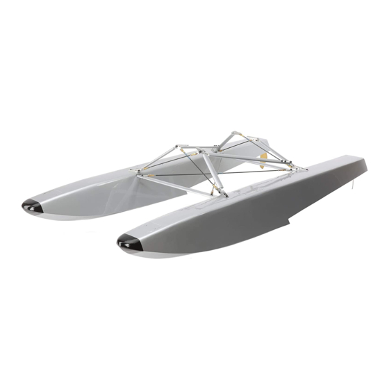
- Page 2 LARGE PARTS LAYOUT • BAUTEILE (OHNE KLEINTEILE) • GRANDES PIÈCES • SCHEMA DEI COMPONENTI GRANDI SPECIFICATIONS • SPEZIFIKATIONEN • SPÉCIFICATIONS • SPECIFICHE inches (564mm) inches (1067mm) inches (175mm) inches (418mm) inches (225mm) inches (49mm) inches (15.5mm) inches (57mm) inches (83mm)
- Page 3 Part # English Deutsch Français Italiano REPLACEMENT PARTS • ERSATZTEILE • PIÈCES DE RECHANGE • PEZZI DI RICAMBIO HAN603001 1/5-Scale Float: Left Schwimmer links: 1/5-Scale Flotteur 1/5: Gauche Galleggiante scala 1/5: sinistro HAN603002 1/5-Scale Float: Right Schwimmer rechts: 1/5-Scale Flotteur 1/5: Droit Galleggiante scala 1/5: destro HAN603003 Float Strut Set...
- Page 4 NOTICE Batteries Always follow the manufacturer’s instructions when using and disposing of any batteries. Mishandling of Li-Po All instructions, warranties and other collateral documents are subject to change at the sole discretion of Horizon batteries can result in fi re causing serious injury and damage. Hobby, LLC.
- Page 5 HINWEIS Propeller Halten Sie lose Gegenstände die sich im Propeller verfangen können weg vom Propeller. Dieses gilt auch für Kleidung Alle Anweisungen, Garantien und anderen zugehörigen Dokumente können im eigenen Ermessen von Horizon Hobby, oder andere Objekte wie zum Beispiel Stifte oder Schraubendreher. LLC.
- Page 6 REMARQUE L’hélice Gardez éloignés tous les éléments qui pourraient être attrapés par l’hélice. Cela inclut les vêtements larges ou les La totalité des instructions, garanties et autres documents est sujette à modifi cation à la seule discrétion d’Horizon objets comme des outils par exemple. Gardez toujours vos mains à distance pour éviter tout cas de blessures. Hobby, LLC.
- Page 7 AVVISO Elica Tenere gli oggetti liberi (vestiti, penne, cacciaviti, ecc.) lontano dall’elica, prima che vi restino impigliati. Bisogna fare Tutte le istruzioni, le garanzie e gli altri documenti pertinenti sono soggetti a cambiamenti a totale discrezione di attenzione anche con le mani perché c’è il rischio di ferirsi anche gravemente. Horizon Hobby, LLC.
- Page 8 SERVO INSTALLATION Remove the covers for the servos and weights. Thread Thread a servo mounting screw into each hole. Remove an M2 x 8 sheet metal screw into each of the mounting the screws. holes. Remove the screws. Use a #1 Phillips screwdriver during this step.
- Page 9 11. Secure a 12-inch (300mm) servo extension to the servo 16. Slide the pushrod wire into the pushrod tube in the rear of lead using a commercially available connector. the fl oat. Guide the wire through the pushrod connector at the servo. 12.
- Page 10 JOINING THE FLOATS Thread an M3 x 25 machine screw into each of the blind Remove the end of one of the longer support braces. Slide nuts in both fl oats. If the screw binds, use a 3mm tap to the tubing onto the brace, then place the end back on the clear the threads.
- Page 11 FLOAT INSTALLATION 11. Use two nylon washers, an M3 x 12 socket head cap Attach the mounting bracket to the rear diagonal brace screw and M3 lock nut to attach the cross brace and using an M3 x 15 socket head cap screw, two nylon diagonal brace to the front mounting bracket.
- Page 12 CENTER OF GRAVITY Carefully remove the nut and screw at the front mounting When installing the fl oats on your model, you must check the Center of Gravity before fl ying. The installation of the fl oats will change the Center of Gravity, and as such, could cause some undesirable fl ight characteristics or even bracket.
- Page 13 PREFLIGHT CHECKLIST DAILY FLIGHT CHECKS LIMITED WARRANTY Limitation of Liability HORIZON SHALL NOT BE LIABLE FOR SPECIAL, INDIRECT, • Charge the transmitter, receiver and motor battery for • Check the battery voltage of the transmitter battery. What this Warranty Covers INCIDENTAL OR CONSEQUENTIAL DAMAGES, LOSS OF your airplane.
- Page 14 WARRANTY AND SERVICE CONTACT INFORMATION Inspection or Services Warranty Requirements If this Product needs to be inspected or serviced and is For Warranty consideration, you must include your compliant in the country you live and use the Product original sales receipt verifying the proof-of-purchase in, please use the Horizon Online Service Request date.
- Page 15 SERVO EINBAU Nehmen Sie die Abdeckung ab. Drehen Sie eine M2 x 8 Drehen Sie eine Servoschraube in jedes Loch und drehen Metallschraube in jedes Schraubloch. Entfernen Sie die Sie wieder heraus. Schrauben wieder. Verwenden Sie zum Einschrauben einen #1 Phillips Schraubendreher. Geben Sie 2 bis 3 Tropfen dünnfl...
- Page 16 11. Verbinden Sie eine 300mm lange Servoakbelverlängerung 16. Schieben Sie das Rudergestänge von hinten in das mit dem Servokabel und sichern diese mit einem Röhrchen im Schwimmer und dann weiter in den Verbinder. Gestängeschanschluss am Servo. 12. Drehen Sie mit einem # 2 Phillips Schraubendreher eine 17.
- Page 17 MONTAGE DER SCHWIMMER Drehen Sie eine M3 x 25 Maschinenschraube in jede der Drehen Sie das Endstück der längeren Verspannungen Blindmuttern. Sollte die Schraube klemmen arbeiten Sie ab. Schieben Sie den Schlauch auf die Verspannung und das Gewinde mit einem 3mm Gewindeschneider nach. drehen das Endstück wieder auf.
- Page 18 MONTAGE DER SCHWIMMER. 11. Schrauben Sie mit einer M3 x 12 Inbusschraube und M3 Montieren Sie den hinteren diagonalen Halter mit Stopmmuter sowie zwei Unterlegscheiben die diagonale einer M3 x 15 Sechskantschraube, zwei Nylon und Kreuzverspannung an den Halter. Verwenden Sie Unterlegscheiben und einer einer M3 Stopmutter.
- Page 19 DER SCHWERPUNKT Entfernen Sie vorsichtig die Schraube und Mutter am Nach der Montage der Schwimmer am Modell muß vor dem Fliegen der Schwerpunkt geprüft werden da sich dieser geändert hat. Änderungen im Schwerpunkt können die Flugeigenschaften erheblich verändern und im schlimmsten vorderen Halter.
- Page 20 VORFLUGKONTROLLE TÄGLICHER FLUG CHECK GARANTIE UND SERVICE Horizon behält sich vor, alle eingesetzten Komponenten zu prüfen, die in den Garantiefall einbezogen werden INFORMATIONEN • Laden Sie den Sender- ,Empfänger- und Zündakku • Überprüfen Sie die Spannung des Senderakkus. können. Die Entscheidung zur Reparatur oder zum für Ihr Flugzeug.
- Page 21 Sicherheitshinweise Fragen, Hilfe und Reparaturen Bitte legen Sie dem Produkt einen Kaufbeleg bei, sowie ACHTUNG: Kostenpfl ichtige Reparaturen nehmen wir Dieses ist ein hochwertiges Hobby Produkt und kein Ihr lokaler Fachhändler und die Verkaufstelle können eine ausführliche Fehlerbeschreibung und eine Liste aller nur für Elektronik und Motoren vor.
- Page 22 INSTALLATION DU SERVO Retirez les couvercles pour les servos et poids. Vissez Vissez les vis de montage du servo dans chaque trou. une vis taraudeuse M2 x 8 dans chaque trou de montage. Retirez les vis. Retirez les vis. Utilisez un tournevis cruciforme #1 pour cette étape.
- Page 23 11. Installez une rallonge servo de 300mm sur le câble servo 16. Passez le câble dans le tube de tringlerie à l’arrière du en utilisant un connecteur disponible dans le commerce. fl otteur. Passez le câble dans le connecteur tringlerie au servo.
- Page 24 ASSEMBLAGE DES FLOTTEURS Vissez une vis M3 x 25 dans chaque écrou borgne des Retirez l’extrémité de l’une des entretoises de support deux fl otteurs. Si la vis accroche, utilisez un taraud de longues. Passez le tube sur l’entretoise puis remettez 3mm pour nettoyer le pas de vis.
- Page 25 INSTALLATION DES FLOTTEURS 11. Utilisez deux rondelles en nylon, une vis BTR M3 x 12 Attachez le support de montage sur le tirant diagonal et un écrou M3 pour attacher les tirants transversaux et arrière à l’aide d’une vis BTR M3 x 15, de deux rondelles diagonaux sur le support de montage avant.
- Page 26 CENTRE DE GRAVITÉ Retirez délicatement l’écrou et la vis du support de Lorsque vous installez des fl otteurs sur votre modèle, vous devez vérifi er le centre de gravité avant de voler. L’installation de fl otteurs va modifi er le centre de gravité et donc entrainer des caractéristiques de vol indésirables ou montage avant.
- Page 27 CHECKLIST D’AVANT VOL CONTRÔLES SYSTÉMATIQUES GARANTIE ET RÉPARATIONS Limitation des dommages Horizon ne saurait être tenu pour responsable de • Chargez la batterie de votre émetteur, de réception • Contrôlez la tension de la batterie de l’émetteur. Durée de la garantie dommages conséquents directs ou indirects, de pertes et d’allumage.
- Page 28 Questions, assistance et réparations Garantie et réparations ATTENTION: Nous n’effectuons de réparations Votre revendeur spécialisé local et le point de vente Les demandes en garantie seront uniquement traitées payantes que pour les composants électroniques ne peuvent effectuer une estimation d’éligibilité à en présence d’une preuve d’achat originale émanant et les moteurs.
- Page 29 INSTALLAZIONE SERVI Togliere i coperchi per i servi e i pesi. Avvitare una vite Avvitare in ciascun foro una vite per il montaggio del autofi lettante M2x8 in ciascun foro di montaggio. Togliere servo e poi toglierla. le viti usando un cacciavite Phillips #1. Mettere in ogni foro 2 o 3 gocce di colla CA liquida per Mettere in ciascun foro 2 o 3 gocce di colla CA liquida indurire la fi...
- Page 30 11. Fissare in modo sicuro al cavo del servo una prolunga da 16. Inserire il fi lo del rinvio nel tubo predisposto nella parte 300mm. posteriore del galleggiante. Far passare il fi lo attraverso il morsetto del rinvio per arrivare al servo. 12.
- Page 31 UNIRE I GALLEGGIANTI Avvitare una vite M3x25 cilindrica in ciascun dado cieco Togliere il terminale da uno dei supporti più lunghi. Far su entrambi i galleggianti. Se le viti dovessero forzare, scorrere il tubo sul supporto, poi mettere di nuovo il usare un maschio da 3mm per pulire i fi...
- Page 32 INSTALLAZIONE DEI GALLEGGIANTI 11. Per fi ssare i montanti trasversali e i tiranti diagonali Fissare la staffa di montaggio al tirante diagonale alla staffa di montaggio anteriore, bisogna usare due posteriore con una vite a brugola M3x15, due rondelle in rondelle in nylon, una vite a brugola M3x12 e un dado nylon e un dado autobloccante M3.
- Page 33 BARICENTRO (CG) Togliere con attenzione il dado e la vite dalla staffa di Quando si installano i galleggianti sul proprio modello, bisogna sempre controllare il baricentro prima di andare in volo. L’installazione dei galleggianti cambierà la posizione del baricentro e quindi potrebbe causare degli assetti di montaggio anteriore.
- Page 34 LISTA DEI CONTROLLI PRIMA DEL VOLO CONTROLLI DI VOLO GIORNALIERI GARANZIA Questa garanzia non copre danni dovuti ad un’installazione errata, ad un funzionamento errato, • Caricare le batterie di trasmettitore, ricevitore • Controllare la tensione della batteria del trasmettitore. Periodo di garanzia ad una manutenzione o un tentativo di riparazione e accensione motore usando i caricabatterie Non volare se la tensione è...
- Page 35 Domande, assistenza e riparazioni Garanzia e riparazione ATTENZIONE: Le riparazioni a pagamento sono Il vostro negozio locale e/o luogo di acquisto non Le richieste in garanzia verranno elaborate solo se è disponibili solo sull’elettronica e sui motori. Le possono fornire garanzie di assistenza o riparazione presente una prova d’acquisto in originale proveniente riparazioni a livello meccanico, soprattutto per senza previo colloquio con Horizon.
- Page 36 www.modellmarkt24.ch www.modellmarkt24.ch...
- Page 37 www.modellmarkt24.ch www.modellmarkt24.ch...
- Page 38 www.modellmarkt24.ch www.modellmarkt24.ch...
- Page 39 Veuillez utiliser ce modèle si vous installez les fl otteurs 1/5 sur des modèles autres que HAN Carbon Cub. Usare questo template quando andrete ad installare i galleggianti in scala 1/5 in un modello che non sia l’Hangar 9 Carbon Cub.
- Page 40 © 2016 Horizon Hobby, LLC. Hangar 9 and the Horizon Hobby logo are registered trademarks of Horizon Hobby, LLC. The Spektrum trademark is used with permission of Bachmann Industries, Inc. All other trademarks, service marks and logos are the property of their respective owners. Patents pending.
Need help?
Do you have a question about the HAN6030 and is the answer not in the manual?
Questions and answers