Advertisement
Quick Links
Advertisement

Subscribe to Our Youtube Channel
Related Manuals for Insportline 22636


Summary of Contents for Insportline 22636
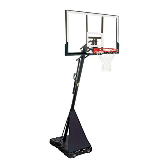
- Page 1 USER MANUAL – EN IN 22636 Basketball basket inSPORTline Cleveland Steel...
-
Page 2: Table Of Contents
CONTENTS SAFETY INSTRUCTIONS ........................3 PARTS LIST ............................4 ASSEMBLY ............................. 8 MOVING ..............................14 HEIGHT ADJUSTMENT ........................14 ENVIRONMENT PROTECTION ......................14 TERMS AND CONDITIONS OF WARRANTY, WARRANTY CLAIMS ..........14... -
Page 3: Safety Instructions
SAFETY INSTRUCTIONS Please read the instruction carefully. Remove all parts and hardware from the carton and place them on soft and clean surface. Check that nothing is missing. Please recycle all packaging materials. • Follow the instructions carefully. Failure to follow these instructions may result in serious injury or damage. -
Page 4: Parts List
PARTS LIST Specifications / Name Picture Qty. A1,A2,A3,A4 M12*180MM B1,B2,B3,B4 M12*180MM C1,C2,C3,C4 M12*180MM D1,D2,D3 M12*180MM E1,E2 M10*180MM F1,F2,F3,F4 M10*120MM G1,G2,G3 M10*100MM H1,H2,H3,H4 M10*100MM I1,I2,I3,I4 M8*90MM J1,J2,J3 M8*100MM K1,K2,K3 M8*45MM... - Page 5 L1,L2,L3 M8*20MM M1,M2,M3 M8*16MM N1,N2 M8*20MM P1,P2 M8*20MM O1,O2 M8*35MM Wheels Base chassis Left base side Right base side Rear base side Pole bracket Top pole cap...
- Page 6 Mesh Holder Small spring Board rod (short) Board rod (long) Post support (U1, U2) Big spring Top pole Middle pole Bottom pole Bracket Board Outer height adjustment rod...
- Page 7 Inner height adjustment rod Protective cover Plate Plate...
-
Page 8: Assembly
ASSEMBLY WARNING! Assembly can only be performed by an adult. 4 adults are recommended for installation. Step 1 Create a pole by joining poles W, X, Y. Attach the bracket Q to the pole X with bolts, washers, and nuts J1, J2, J3. Step 2 Tighten the pole with a few strikes against a piece of wood. - Page 9 Step 3 As shown, attach the four wheels H to the base chassis I with bolt M1, M2, M3. Notice that the two wheels H are directional, located on the front. The two wheels H are universal and are located at the rear. Step 4 Attach the pole bracket N to the left J and right K sides of the base with bolts and washers O1, O2.
- Page 10 Step 5 Attach the bottom pole Y to the pole bracket N with bolts and washers N1, N2. Step 6 Supports U1, U2 attach to the pole X with bolts, washers, and nuts F1, F2, F3, F4. Supports U must be facing each other.
- Page 11 Step 8 Attach the rim AA to the board CC with bolts, washers, and nuts I1, I2, I3, I4 a L1, L2, L3, L4. Two small springs R must be attached to the holes in the rim AA with bolts I1, I2, I3, I4. Step 9 Attach rods S, T to the board CC with bolts, washer and nuts C1, C2, C4.
- Page 12 Step 10 Attah the bracket Z to the top pole W with bolts, washers, and nuts H1, H2, H3, H4. Bushing H3 must be inserted to the top pole W. Bolt H1 tighten after attaching rods S, T. Attach the rods S and T to the bracket Z as shown with bolts, washers, and nuts B1, B3, B4, D1, D2, D3, D4.
- Page 13 Step 12 Hook the two large springs V into the fourth hole in the board holder. Step 13 Attach net P to the rim AA. Step 14 Pour sand or water into the base.
-
Page 14: Moving
MOVING • Lower the basket to the lowest position. • Grasp the post and tilt the base onto the wheels. • Move the basket on the wheels. • Place the basket in the desired location. • Check the stability of the basket. HEIGHT ADJUSTMENT Height can be adjusted by handle EE. - Page 15 These Conditions of Warranty and Warranty Claims are an integral part of every Purchase Agreement made between the Seller and the Buyer. All Warranty Conditions are valid and binding, unless otherwise specified in the Purchase Agreement, in the Amendment to this Contract or in another written agreement.
- Page 16 26847264 VAT ID: CZ26847264 Phone: +420 556 300 970 E-mail: eshop@insportline.cz reklamace@insportline.cz servis@insportline.cz Web: www.inSPORTline.cz inSPORTline s.r.o. Headquaters, warranty & service center: Električná 6471, Trenčín 911 01, SK CRN: 36311723 VAT ID: SK2020177082 Phone: +421(0)326 526 701 E-mail: objednavky@insportline.sk reklamacie@insportline.sk servis@insportline.sk...
Need help?
Do you have a question about the 22636 and is the answer not in the manual?
Questions and answers