
Subscribe to Our Youtube Channel
Related Manuals for Aaeon HSB-835P


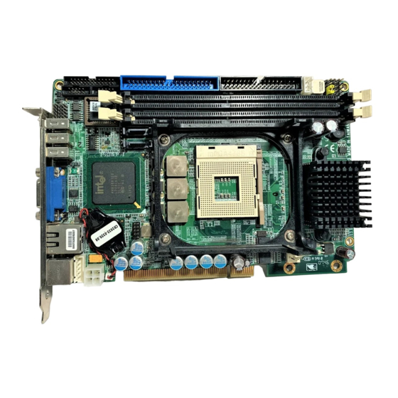
Summary of Contents for Aaeon HSB-835P
- Page 1 H a l f - s i z e C P U C a r d H S B - 8 3 5 P HSB-835P ® ® Intel Pentium 4 Processor PICMG/PCI Half-size CPU Card With DDR, Ethernet, ™ CompactFlash & SATA HSB-835P Rev. A Manual 1st Ed. Mar. 2005...
- Page 2 AAEON assumes no liabilities resulting from errors or omissions in this document, or from the use of the information contained herein. AAEON reserves the right to make changes in the product design without notice to its users.
- Page 3 H a l f - s i z e C P U C a r d H S B - 8 3 5 P Acknowledgments All other products’ name or trademarks are properties of their respective owners. Award is a trademark of Award Software International, Inc. ™...
- Page 4 H a l f - s i z e C P U C a r d H S B - 8 3 5 P Packing List Before you begin installing your card, please make sure that the following materials have been shipped: • HSB-835P CPU Card • Floppy Cable • ATA-100 Cable •...
-
Page 5: Table Of Contents
H a l f - s i z e C P U C a r d H S B - 8 3 5 P Contents Chapter 1 General Information 1.1 Introduction..............1-2 1.2 Feature ..............1-4 1.3 Specification .............. 1-5 Chapter 2 Quick Installation Guide 2.1 Safety Precaution ............ - Page 6 H a l f - s i z e C P U C a r d H S B - 8 3 5 P 2.18 AC97 Connector (CN3) ........... 2-11 2.19 PS/2 Keyboard & Mouse Connector (CN4) .... 2-12 2.20 Internal Keyboard Connector (CN5)......2-12 Chapter 3 Award BIOS Setup 3.1 System Test and Initialization.
-
Page 7: Chapter 1 General Information
H a l f - s i z e C P U C a r d H S B - 8 3 5 P Chapter General Information 1- 1 Chapter 1 General Information... -
Page 8: Introduction
USB 2.0 ports. ® HSB-835P successfully deployed Intel most advanced 865GV chipset, which supports high CPU frequency up to 3.2 GHz with front side bus running at 400/533/800MHz. HSB-835P supports ® Intel Hyper-Threading Technology gives you the best overall ®... - Page 9 VPN, Mini server and etc. ® HSB-835P is a versatile Pentium 4/ Prescott compact board with the best cost-performance for CTI, networking and mini-server markets. For these diverse applications, HSB-835P definitely is your best choice. Chapter 1 General Information 1 - 3...
-
Page 10: Feature
H a l f - s i z e C P U C a r d H S B - 8 3 5 P 1.2 Feature • ® ® Supports Intel Pentium 4 CPU up to 3.2GHz (Prescott CPU) • Supports DDR400 Memory up to 2GB •... -
Page 11: Specification
H a l f - s i z e C P U C a r d H S B - 8 3 5 P 1.3 Specification System ® ® CPU: Supports Intel Pentium ® and Celeron processors up to 3.2 GHz (400/533/ 800 MHz FSB) ®... - Page 12 H a l f - s i z e C P U C a r d H S B - 8 3 5 P Expansion Interface: PICMG/ PCI interface Power Supply Request: +12V ATX, other supply from Backplane ® VGA Controller: Integrated on Intel 865G, AGP 8X, Core frequency up...
- Page 13 H a l f - s i z e C P U C a r d H S B - 8 3 5 P floppy devices) Serial Ports: Two COM ports: (Internal pin header, external D-sub x COM 1: RS-232 COM 2: RS-232/422/485 Parallel Port: Supports SPP/EPP/ECP...
- Page 14 H a l f - s i z e C P U C a r d H S B - 8 3 5 P Chapter Quick Installation Guide Notice: The Quick Installation Guide is derived from Chapter 2 of user manual. For other chapters further installation...
-
Page 15: Safety Precaution
H a l f - s i z e C P U C a r d H S B - 8 3 5 P 2.1 Safety Precaution Always completely disconnect the power cord from your board whenever you are working on it. -
Page 16: Location Of Connectors And Jumpers
H a l f - s i z e C P U C a r d H S B - 8 3 5 P 2.2 Location of Connectors and Jumpers Component Side Solder Side Chapter 2 Quick Installation Guide 2 - 3... -
Page 17: Mechanical Drawing
H a l f - s i z e C P U C a r d H S B - 8 3 5 P 2.3 Mechanical Drawing Component Side Solder Side Chapter 2 Quick Installation Guide 2 - 4... -
Page 18: List Of Jumpers
H a l f - s i z e C P U C a r d H S B - 8 3 5 P 2.4 List of Jumpers The board has a number of jumpers that allow you to configure your system to suit your application. -
Page 19: List Of Connectors
H a l f - s i z e C P U C a r d H S B - 8 3 5 P 2.5 List of Connectors The board has a number of connectors that allow you to configure your system to suit your application. -
Page 20: Setting Jumpers
H a l f - s i z e C P U C a r d H S B - 8 3 5 P 2.6 Setting Jumpers You configure your card to match the needs of your application by setting jumpers. A jumper is the simplest kind of electric switch. It consists of two metal pins and a small metal clip (often protected by a plastic cover) that slides over the pins to connect them. -
Page 21: Clear Cmos (Jp1)
H a l f - s i z e C P U C a r d H S B - 8 3 5 P 2.7 Clear CMOS (JP1) Function Clear CMOS Open Protected (Default) 2.8 Front Panel Connector (FP1) Signal Signal Power On Button (+) Reset Switch (+) -
Page 22: Rs-232 Serial Port Connector (Com1)
H a l f - s i z e C P U C a r d H S B - 8 3 5 P 2.10 RS-232 Serial Port Connector (COM1) Signal Signal 2.11 RS-232/422/485 Serial Port Connector (COM2) Signal Sign al DCD(422TXD-/485DATA-) RXD(422RXD+) TXD(422TXD+/485DATA+) -
Page 23: Lpt Port Connector (Lpt1)
H a l f - s i z e C P U C a r d H S B - 8 3 5 P 2.13 LPT Port Connector (LPT1) Signal Sign al #STROBE #AFD DATA0 #ERROR DATA1 #INIT DATA2 #SLIN DATA3 DATA4 DATA5... -
Page 24: Fan Connector (Fan1)
H a l f - s i z e C P U C a r d H S B - 8 3 5 P 2.15 Fan Connector (FAN1) Signal +12V Speed Sense 2.16 ATX Power Control Connector (CN1) AT Power Use: Close Pin 2, 3 Signal PS-ON 5VSB... -
Page 25: Ps/2 Keyboard & Mouse Connector (Cn4)
H a l f - s i z e C P U C a r d H S B - 8 3 5 P 2.19 PS/2 keyboard & Mouse Connector (CN4) Signal KB_DATA MS_DATA KB_CLK MS_CLK 2.20 Internal Keyboard Connector (CN5) Signal KB_CLK KB_DATA... -
Page 26: Chapter 3 Award Bios Setup
H a l f - s i z e C P U c a r d H S B - 8 3 5 P Chapter Award BIOS Setup Chapter 3 Award BIOS Setup... - Page 27 3. The CMOS memory has lost power and the configuration information has been erased. The HSB-835P CMOS memory has an integral lithium battery backup for data retention. However, you will need to replace the complete unit when it finally runs down.
- Page 28 H a l f - s i z e C P U c a r d H S B - 8 3 5 P 3.2 Award BIOS Setup Awards BIOS ROM has a built-in Setup program that allows users to modify the basic system configuration. This type of information is stored in battery-backed CMOS RAM so that it retains the Setup information when the power is turned off.
- Page 29 H a l f - s i z e C P U c a r d H S B - 8 3 5 P up, etc.) PnP/PCI Configurations This entry appears if your system supports PnP/PCI. PC Health Status This menu allows you to set the shutdown temperature for your system.
- Page 30 H a l f - s i z e C P U c a r d H S B - 8 3 5 P Abandon all CMOS value changes and exit setup. You can refer to the "AAEON BIOS Item Description.pdf" file in the CD for the meaning of each setting in this chapter.
-
Page 31: Chapter 4 Driver Installation
H a l f - s i z e C P U C a r d H S B - 8 3 5 P Chapter Driver Installation Chapter 4 Driver Installation... -
Page 32: Installations
H a l f - s i z e C P U C a r d H S B - 8 3 5 P The HSB-835P comes with a CD-ROM that contains all drivers and utilities that meet your needs. - Page 33 H a l f - s i z e C P U C a r d H S B - 8 3 5 P 4.1 Installation: Insert the HSB-835P CD-ROM into the CD-ROM Drive. And install the drivers from Step 1 to Step 6 in order. Step 1 – Install Intel INF Update 1.
- Page 34 H a l f - s i z e C P U C a r d H S B - 8 3 5 P Step 4 – Install AC97 Audio Driver 1. Click on the Realtek_ALC65X_AudioDriver_Windows(RevA3.61) folder and then enter ALC655 folder. 2.
- Page 35 H a l f - s i z e C P U C a r d H S B - 8 3 5 P 3. The system will help you install the driver automatically. 4. Please re-start your computer. Note: Under the Window OS environment, if the CRT connector is connected to display monitor by the data switch device, the user need to set the color and resolution from Intel Graphic...
-
Page 36: Appendix A I/O Information
H a l f - s i z e C P U C a r d H S B - 8 3 5 P Appendix I/O Information Appendix A I/O Information... -
Page 37: I/O Address Map
H a l f - s i z e C P U C a r d H S B - 8 3 5 P A.1 I/O Address Map Appendix A I/O Informaion... -
Page 38: St Mb Memory Address Map
H a l f - s i z e C P U C a r d H S B - 8 3 5 P A.2 1 MB Memory Address Map Appendix A I/O Informaion... -
Page 39: Irq Mapping Chart
H a l f - s i z e C P U C a r d H S B - 8 3 5 P A.3 IRQ Mapping Chart Appendix A I/O Informaion... -
Page 40: Dma Channel Assignments
H a l f - s i z e C P U C a r d H S B - 8 3 5 P A.4 DMA Channel Assignments Appendix A I/O Informaion... -
Page 41: Appendix B Programming The Watchdog Timer
H a l f - s i z e C P U C a r d H S B - 8 3 5 P Appendix Programming the Watchdog Timer Appendix B Programming the Watchdog Timer... -
Page 42: Programming
H a l f - s i z e C P U C a r d H S B - 8 3 5 P B.1 Programming HSB-835P utilizes W83627HF chipset as its watchdog timer controller. Below are the procedures to complete its configuration and... - Page 43 H a l f - s i z e C P U C a r d H S B - 8 3 5 P There are three steps to complete the configuration setup: (1) Enter the W83627HF config Mode (2) Modify the data of configuration registers (3) Exit the W83627HF config Mode.
- Page 44 H a l f - s i z e C P U C a r d H S B - 8 3 5 P 0aah: WatchDog Timer Register I (Index=F5h, Default=00h) CRF5 (PLED mode register. Default 0 x 00) Bit 7-6 : select PLED mode = 00 Power LED pin is tri-stated.
- Page 45 H a l f - s i z e C P U C a r d H S B - 8 3 5 P = 0 x 02 Time-out occurs after 2 second/minutes = 0 x 03 Time-out occurs after 3 second/minutes ………………………………..
- Page 46 H a l f - s i z e C P U C a r d H S B - 8 3 5 P Watchdog Timer time-out occurred Watchdog Timer counting Bit 3-0 : These bits select IRQ resource for Watchdog.
-
Page 47: W83627Hf Watchdog Timer Initial Program
H a l f - s i z e C P U C a r d H S B - 8 3 5 P B.2 W83627HF Watchdog Timer Initial Program Example: Setting 10 sec. as Watchdog timeout interval ;/////////////////////////////////////////////////////////////////////////////////////////////// Mov dx,2eh ;Enter W83627HF config mode Mov al,87h (out 87h to 2eh twice) - Page 48 H a l f - s i z e C P U C a r d H S B - 8 3 5 P ;/////////////////////////////////////////////////////////////////////////////////////////////// Dec dx Mov al,0f5h ;CRF5 (PLED mode register) Out dx,al Inc dx In al,dx And al,not 08h ;Set second as counting unit Out dx,al ;///////////////////////////////////////////////////////////////////////////////////////////////...
Need help?
Do you have a question about the HSB-835P and is the answer not in the manual?
Questions and answers