Advertisement
Quick Links
Advertisement

Related Manuals for GoPowerBike GoEagle


Summary of Contents for GoPowerBike GoEagle
- Page 1 GOPOWERBIKE...
- Page 2 Welcome Thank you for purchasing the GoEagle from GoPowerbike. Please read carefully and understand this manual fully before assembling and riding your bike. If you have questions after reading this manual, please contact us by email, and/or give us a call on the phone.
- Page 3 WWW.GOPOWERBIKE.COM RETURN STORE. If you need any help with your new GoEagle Bike whether i t is missing parts or need assistance with assembly, please Email help@gopowerbike.com or call us at 917-900-1110 _ we will be sure to respond within the same business...
- Page 4 Keep this manual, along with any other documents that were included with your bike, for future reference, however all content in this manual is subject to change or withdrawal without notice. GoPowerbike makes every effort to ensure the accuracy of its documentation and assumes no responsibility or liability if any errors or inaccuracies appear within.
-
Page 5: Table Of Contents
Table of Contents General Info Assembly Instructions Battery Charging Operation Maintenance Warnings and Safety Warranty... -
Page 6: General Info
NOTICE: A critical aspect of assembling your bike by GoPowerbike is securing the front wheel and checking the tightness of the rear wheel axle nuts. All bikes by GoPowerbike use a quick release front wheel mounting mechanism and the rear wheel is bolted on. - Page 7 The throttle should provide smooth acceleration when gradually applied. If the throttle, brake lever cutoff switches, pedal assistance, or lighting are functioning abnormally, intermittently, or not working, please discontinue using your ebike immediately and contact the GoPowerbike Product Support team for assistance.
- Page 8 Loose, worn, or damaged handlebar grips should be replaced before you ride and can be purchased from GoPowerbike. The seat and seatpost should be properly aligned, fitted to the user, and the seatpost quick release should be properly tightened, fully closed, and secured before riding.
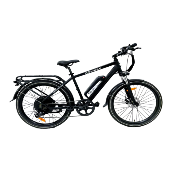
- Page 9 Fully Assembled GoEagle...
-
Page 10: Assembly Instructions
Unpack the bike. Open the bike box and remove the small box inside. With the help of another person capable of safely lifting a heavy object, remove the GoEagle from the bike box. Carefully remove the packaging material protecting the bike frame and components. Please recycle packaging materials especially cardboard and foam whenever possible. - Page 11 Step 1: Twist the handlebar stem to correct position as shown below...
- Page 12 Step 2: Install handlebar onto stem A. Place the handlebar on the stem correctly. Trace the front brake cable directly up from the front brake caliper to the left handlebar and ensure the cables and wires are not twisted. B. Locate the four handlebar faceplate bolts in the accessory box. C.
- Page 13 Step 3: Install the front wheel. Locate the quick release lever, -Twist the cap off the Quick Release Clamping Lever along with the cone spring as circled below...
- Page 14 Install the skewer into the front wheel axle from the brake rotor side. Reinstall the cone spring so it points toward the wheel hub then thread the thumb nut onto the skewer only a couple turns, leaving room for the fork dropouts. Make sure the lever is open and carefully lower the fork onto the axle and brake caliper as shown below...
- Page 15 Fully seat the skewer in the fork dropouts (and the brake rotor in the caliper) and add tension to the lever by turning the thumbnut, as shown below When there is enough resistance to hold the quick release lever in line with the axle, close the lever using the palm of your hand without touching the brake rotor as shown below...
- Page 16 When properly installed, the front wheel should be fully seated and centered in the dropouts of the front fork, the brake rotor should be in between the brake pads in the brake caliper, and the quick release lever should be fully and properly secured.
- Page 17 Step 4: Lock the handlebar stem by tightening the screws as shown below Please make sure that the front wheel is aligned to the handlebar before tightening)
- Page 18 Step 5: Install Front Fender and Headlight. Remove headlight screw and slide the fender under the fork, above the tire. Position the mounting point to be in the back of the fork by the screw hole, layering the headlight first, then the fender mounting point (as shown below).
- Page 19 Then unscrew the 2 screws and bolts on both sides right below the fork (see image below), and screw the fender mounting arms in. Lastly, plug the headlight in by lining up the two front arrows and press them straight together without twisting.
- Page 20 Step 6: Install the pedals. Locate the pedal with a smooth pedal axle exterior and an engraved “R”, which indicates it is the right pedal (as shown below). The right pedal goes on the crank on the right side of the bike (which has the drivetrain gears and is the same as a rider’s right side when riding).
- Page 21 The left pedal (2) is reverse-threaded and tightens counterclockwise. The pedal has an engraved “L” into the end of the axle (pictured below), indicating it is the left pedal. Carefully thread the pedal onto the left crank by hand slowly by tightening counterclockwise.
- Page 22 Torque each pedal to 35 Nm. Use the pedal wrench provided to avoid damage caused by wider wrenches. Right pedal tightens clockwise. Left pedal tightens counterclockwise.
- Page 23 Step 7: Inflate the tires. Check that the tire beads and tires are evenly seated on the rims. Use a pump with a Schrader valve and pressure gauge to inflate each tire to the recommended pressure indicated on the tire sidewall, 20 PSI (1.38 Bar). Do not overinflate or underinflate tires.
- Page 24 Step 8: Set the desired seat height. Open the quick release lever by hinging it open fully. Ensure the seatpost clamp opening is aligned with the notch at the front of the seat tube. Adjust the seatpost up or down to a comfortable height, while ensuring the seatpost is inserted into the frame past the minimum insertion point.
- Page 25 NOTICE: If you have any questions regarding the assembly of your bike, contact GoPowerbike. If you are not able to ensure all the assembly steps are performed properly, please consult a certified, reputable local bike mechanic for assistance in addition to contacting GoPowerbike for help.
- Page 26 Adjusting the Seat Position and Angle To change the angle and horizontal position of the seat: 1) Use a 6 mm Allen wrench to loosen the seat adjustment bolt on the clamp positioned immediately underneath the seat, above the rear wheel. Do not remove the bolt fully. 2) Move the seat backward or forward and tilt to adjust the angle.
- Page 27 A bike fitting professional, such as a certified, reputable bike mechanic who specializes in bike fit, should be consulted to ensure you have a good fit. NOTICE: If you have any questions regarding the proper fit of your bike please consult a certified, reputable local bike mechanic for assistance fitting the bike to a rider or contact GoPowerbike.
-
Page 28: Battery Charging
Battery Charging Charging Procedure Follow these steps for charging your bike from GoPowerbike: 1. Ensure the battery is off by having the battery pack on the 0 button 2. Remove the rubber cover on the charging port on the opposite side of the battery from the key 3. - Page 29 Battery Charging Information Check the charger, charger cables, and battery for damage before beginning each charge. Always charge in a safe area that is cool*, dry, indoors, away from direct sunlight, dirt, or debris, in a clear area away from potential to trip on the charging cords, or for damage to occur to the bike, battery, or charging equipment while parked and/or charging.
- Page 30 Use caution to avoid damage to battery connector terminals, which are exposed when the battery is unlocked and removed from the frame of the bike. In the case of damage to the terminals or battery mounts, please discontinue use and contact GoPowerbike Product Support immediately. When Installing the Battery onto the Bike Ensure the battery is off before sliding the battery onto the frame mount receptacle.
- Page 31 Do not charge the battery with any chargers other than the one originally supplied from GoPowerbike or a charger designed for use with your specific bike purchased directly from GoPowerbike.
- Page 32 Long-Term Battery Storage If storing your bike from GoPowerbike for longer than two weeks at a time, follow the instructions below to maintain the health and longevity of your battery. Charge (or discharge) the battery to approximately 75% charged. Power off the battery either locked to the frame or unlocked and removed from the frame for storage Store the battery in a dry, climate controlled, indoor location between 50 °F –...
-
Page 33: Operation
Contact GoPowerbike if you have any questions about assembly or operation. - Page 34 Handlebar Features Location on Handlebar Component LCD Display Remote LCD Display Shifter Throttle...
- Page 35 LCD Display Information The table and image below show the various features and information displayed on the LCD display. Location Information on Display Battery Charge Indicator Distance (Odometer, Trip Odometer) Distance Unit (kilometers (Km), miles (Mile)) Speed Unit (kilometers per hour (Km/h), miles per hour (MPH)) Operation Mode Watt Meter, Error Code Indicator...
- Page 36 LCD Display Operations Operation Directions Turn on bike Press and hold M button until power engages Turn on headlight, taillight, Press and hold up arrow until light illuminates Activate brake light When bike is on, squeeze brake lever Increase pedal assist (PAS) level Press and release up arrow Decrease pedal assist (PAS) level Press and release down arrow...
- Page 37 Start-Up Procedure After the bike has been properly assembled if all components are secured correctly, and you have read this entire manual, you may turn the bike on and select a power level following the steps outlined below: 1) Turn on the battery pack...
- Page 38 2) Press and hold the ‘’M’’ Button for 3 seconds...
- Page 39 3) Turn on the Headlight/Taillight press and hold the UP arrow for 3 seconds...
- Page 40 Begin riding carefully. With the proper safety gear and rider knowledge, Press the red button and you may now operate your bike from GoPowerbike. On a flat surface, in a low gear (1 or 2), most riders should be able to begin pedaling the bike with pedal assist level 0 or 1.
- Page 41 Brake Light Features and Operations Your ebike by GoPowerbike comes equipped with a taillight/brake light that is integrated into the electrical system. Anytime the bike is powered on, squeezing one or both brake levers on the handlebar will cause the brake light to illuminate.
- Page 42 Battery Charge Level Indicator The LCD display on the handlebars of your bike from GoPowerbike features a battery charge level indicator (like a fuel gauge on a car). This indicator calculates battery life based on the battery power output (instantaneous voltage reading) and can fluctuate while riding if power demand and/or output changes.
- Page 43 Driving Range The range of your bike from GoPowerbike is the distance the bike will travel on a single full charge of the onboard battery. The range values in this manual are estimates based on expected usage characteristics of bikes by GoPowerbike. Some of the factors that affect range include changes in elevation, speed, payload, acceleration, number of starts and stops, ambient air temperatures, tire pressure, and terrain.
- Page 44 Carrying Loads MAXIMUM PAYLOAD CAPACITY FOR GOEAGLE The total maximum weight limit, or payload capacity, of the GoEagle (300 LBS) includes the weight of the rider as well as clothing, The GoEagle is compatible with the optional rear rack and safety gear, cargo, accessories, passengers, etc.
-
Page 45: Maintenance
Basic Bike Care To ensure safe riding conditions you must properly maintain your bike from GoPowerbike. Follow these basic guidelines and see a certified, reputable bike mechanic at regular intervals to ensure your bike is safe for use and fun to ride. See the Pre-Ride Safety Checklist and Recommended Service Intervals sections in this manual for more detailed information. - Page 46 Pre-Ride Safety Checklist Notice: Before every ride, and after every 25-45 miles (40-72 km), we advise following the pre-ride safety checklist. Safety Check Basic Steps 1. Brakes Ensure front and rear brakes work properly. Check brake pads for wear and ensure they are not overworn. Ensure brake pads are correctly positioned in relation to the rims.
- Page 47 Check that the frame and fork are not bent or broken. 8. Frame, Fork, If either frame or fork are bent or broken, they should be replaced. and Seat Check that the seat is adjusted properly, and seatpost quick release lever is securely tightened. 9.
- Page 48 Tire Inflation and Replacement The GoEagle employs 26’’ x 4’’ rubber tires with inner tubes. The tires are designed for durability and safety for regular cycling activities and to be checked before each use for proper inflation and condition. Proper inflation, care, and timely replacement will help to ensure that your bike’s operational characteristics will be maintained, and unsafe conditions avoided.
- Page 49 Error Detection Your bike from GoPowerbike is equipped with an error detection system integrated into the display and controller. In the case of an electronic control system fault an error code should display. If your bike has an error code displayed at...
-
Page 50: Warnings And Safety
● Be careful at intersections and when preparing to pass other vehicles or other cyclists. ● Familiarize yourself with all the features and operations of the bike by GoPowerbike. Practice and become proficient at shifting gears, applying the brakes, using the power assist system, and using the throttle in a controlled setting before riding in riskier conditions. - Page 51 Safety Notes The following safety notes provide additional information on the safe operation of your bike from GoPowerbike and should be closely reviewed. Failure to review these notes can lead to serious injury or death. ● All users must read and understand this manual before riding their bike from GoPowerbike. Additional manuals for components used on the bike may also be provided and should be read before installing or using those components.
- Page 52 Wet Weather It is recommended to not ride in wet weather if avoidable. Ride in wet weather only if necessary. This electric bike is not meant for use in puddles, heavy rain, or streams. Never immerse or submerge this product in water or liquid as the electrical system may be damaged.
- Page 53 ● Any aftermarket changes to your bike from GoPowerbike not expressly approved by GoPowerbike could void the warranty and create an unsafe riding experience.
- Page 54 A Note for Parents and Guardians As a parent or guardian, you are responsible for the activities and safety of your child. The GoEagle is not designed for use by children under the age of 18. If you are carrying a passenger in a child safety seat, they should also be wearing a properly fitted and approved helmet.
-
Page 55: Warranty 51
Limited Warranty Warranty Info Every bike by GoPowerbike is covered under a manufacturer's one-year all-inclusive warranty for the original owner against all manufacturing defects. GoPowerbike warrants this product, including all individual components against defects in material or workmanship as follows:... - Page 56 Components of the GoEagle are subject to higher wear when compared to bikes without power assistance. This is because the GoEagle can travel at higher average speeds than regular bicycles and has a greater weight. Higher wear is not a defect in the product and is not subject to warranty.
- Page 57 We are here to help! If you have questions, please: Contact us directly by email to help@gopowerbike.com Call GoPowerbike Product Support 917-900-1110 V5.002...
Need help?
Do you have a question about the GoEagle and is the answer not in the manual?
Questions and answers
Where can I purchase a go city e bike controller in vancouver BC