Table of Contents
Advertisement
Quick Links
Advertisement
Table of Contents
Troubleshooting

Related Manuals for HP Z238


Summary of Contents for HP Z238
- Page 1 HP Z238 Workstation Maintenance and Service Guide...
- Page 2 ENERGY STAR is a registered trademark owned L.P. change without notice. The only warranties for by the U.S. Environmental Protection Agency HP products and services are set forth in the (EPA). First Edition: January 2016 express warranty statements accompanying Intel, Core, Pentium, and Xeon are trademarks such products and services.
- Page 3 About this guide This guide provides service and maintenance information, technical details, and configuration guidance for your workstations. IMPORTANT: Removal and replacement procedures are now available in videos on the HP website. Go to http://www.hp.com/go/sml. Guide topics Hardware overview on page 1...
- Page 4 About this guide...
-
Page 5: Table Of Contents
Table of contents 1 Hardware overview ............................1 HP Z238 Workstation components ........................2 Front panel ............................2 Rear panel ............................3 Chassis components ..........................4 System board components ......................... 5 System board architecture ........................6 Workstation specifications ........................7 Product specifications ............................ - Page 6 HPQFlash ......................... 26 FailSafe Boot Block ..........................26 Recovering the computer by using FailSafe Boot Block recovery mode ......27 Workstation security ......................... 27 Asset tracking ......................... 27 SATA hard drive security ....................28 DriveLock applications ................. 28 Using DriveLock .................... 29 Password security ......................
- Page 7 Diagnosis guidelines ............................49 Diagnosis at startup .......................... 49 Diagnosis during operation ....................... 50 Troubleshooting checklist ........................... 50 HP troubleshooting resources and tools ......................51 Online support ........................... 51 HP Support Center ......................51 HP Chat Support ......................51 Customer Advisories, Customer and Security Bulletins, and Customer Notices ... 51 Product Change Notifications ...............
- Page 8 Testing power supply ...................... 60 Using HP PC Hardware Diagnostics (UEFI) ......................61 Downloading HP PC Hardware Diagnostics (UEFI) to a USB device ..........61 POST error messages and diagnostic front panel LEDs and audible codes ............62 POST numeric codes and text messages ..................63 Interpreting system validation diagnostic front panel LEDs and audible codes ..........
-
Page 9: Hardware Overview
Hardware overview This chapter presents an overview of workstation hardware components. Topics HP Z238 Workstation components on page 2 Product specifications on page 8 Ensuring proper ventilation on page 9... -
Page 10: Hp Z238 Workstation Components
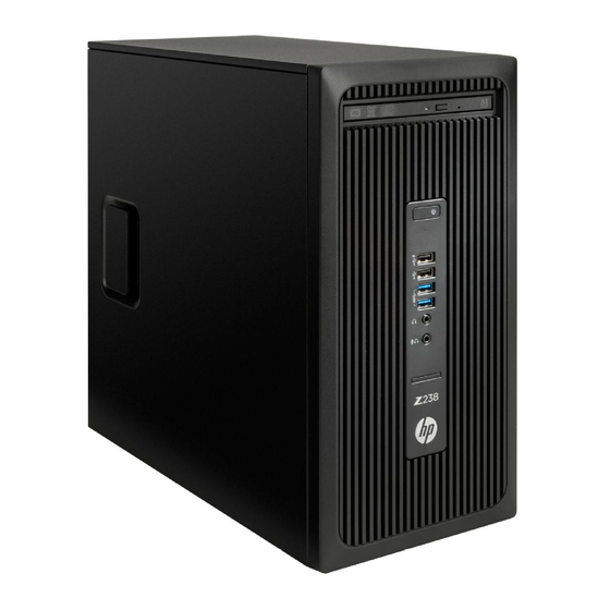
HP Z238 Workstation components This section describes the HP Z238 Workstation components. For complete and current information on supported accessories and components for the computer, see http://partsurfer.hp.com. Front panel Optional optical disc drive (not shown) USB 3.0 ports, SuperSpeed (2) -
Page 11: Rear Panel
Simultaneous usage of integrated Intel HD graphics and discrete graphics cards (in order to drive more than two displays) can be enabled using the Computer (F10) Setup Utility. However, HP recommends using only discrete graphics cards when attaching three or more displays. -
Page 12: Chassis Components
Chassis components The following figure shows the chassis components of a typical workstation layout. Drive configurations can vary. Item Description Item Description Power supply Chassis Side access panel Slim optical drive Cooler/heat sink Hard drive System board Front bezel Chapter 1 Hardware overview... -
Page 13: System Board Components
Expansion slots on page 41 Keyboard/mouse Cooling Hood sensor Network/rear USB 3.0 Processor fan Service Rear audio Rear fan Clear CMOS button Rear USB 3.0 ME/AMT flash override Serial Password jumper Header for serial adapter HP Z238 Workstation components... -
Page 14: System Board Architecture
System board architecture NOTE: The PCIe designators indicate the mechanical connector size and number of electrical PCIe lanes routed to an expansion slot. For example, x16(4) means that the expansion slot is mechanically a x16 length connector, with 4 PCIe lanes supported. Chapter 1 Hardware overview... -
Page 15: Workstation Specifications
"___5" provide Intel HD Graphics P530. NOTE: To drive more than three displays, use Computer Setup (F10) Utility to intermix integrated Intel HD graphics and discrete graphics cards (with four or more displays, HP recommends using only discrete graphics cards). ●... -
Page 16: Product Specifications
Product specifications Workstation weights and dimensions Characteristic HP Z238 Typical configuration 6.99 kg (15.38 lb) Weight Minimum configuration 6.42 kg (14.12 lb) Maximum configuration 7.9 kg (17.42 lb) Height 35.5 cm (14.0 in) Chassis dimensions Width 16.5 cm (6.5 in) Depth 35.6 cm (14.1 in) -
Page 17: Ensuring Proper Ventilation
Ensuring proper ventilation Proper ventilation for the system is important for workstation operation. Follow these guidelines: Operate the workstation on a sturdy, level surface. ● ● Provide at least 15.24 cm (6 inches) of clearance at the front and back of the workstation. (Workstation models vary.) ●... -
Page 18: System Management
System management This section describes the tools and utilities that provide system management for the workstation. Topics Power management and performance features on page 10 BIOS ROM on page 11 Computer Setup (F10) utilities on page 12 Desktop management on page 23 Power management and performance features ERP compliance mode This computer provides ERP compliance mode capability. -
Page 19: Hyper-Threading Technology (Htt)
This feature requires that the operating system support multiple processors and be specifically optimized for HTT. Use Computer Setup (F10) Utility to enable HTT. Go to http://www.hp.com/go/quickspecs to determine if your CPU supports HTT. SATA Power Management SATA Power Management enables or disables SATA bus and/or device power management. -
Page 20: Computer Setup (F10) Utilities
Computer Setup (F10) utilities Use Computer Setup (F10) Utility to do the following: ● Change settings from the defaults or restore the settings to default values. ● View the system configuration, including settings for processor, graphics, memory, audio, storage, communications, and input devices. ●... - Page 21 ● If you have made changes that you do not want applied, select Ignore Changes and Exit. To restore settings from the Advanced and Main menus to original values, select Apply Factory ● Defaults and Exit. ● To restore settings from the Advanced and Main menus to those previously saved by Save Custom Defaults, select Apply Custom Defaults and Exit.
-
Page 22: Computer Setup-Main
Integrated MAC Address System Diagnostics If the hard drive has the HP Advanced Diagnostics installed, the application will launch. If HP Advanced Diagnostics is not installed, then a basic version built into the BIOS will provide the capability to perform the following functions: ●... - Page 23 Update BIOS Using Local Media ● Lets you access files on either USB storage or the hard drive. The HP BIOS Update and Recovery application included in BIOS Softpaqs at www.hp.com will copy the BIOS file to the correct location on the hard drive or USB device.
-
Page 24: Computer Setup-Security
Computer Setup—Security NOTE: Support for specific Computer Setup options may vary depending on the hardware configuration. Table 2-2 Computer Setup—Security Option Description Set up BIOS Lets you set and enable a BIOS administrator password, which includes the following privileges: Administrator Password ●... - Page 25 Table 2-2 Computer Setup—Security (continued) ● Data Recovery Policy Select ‘Automatic’ or ‘Manual’ to set data recovery policy. ‘Manual’ lets you select whether or not to execute recovery of a corrupted region if it is detected. Dynamic Runtime Scanning of Boot Block Verifies the integrity of the BIOS boot block region several times each hour while the system is running.
-
Page 26: Computer Setup-Advanced
Table 2-2 Computer Setup—Security (continued) CAUTION: Restoring a previously saved MBR after a disk utility or operating system has modified the MBR, may cause the data on the disk to become inaccessible. Only restore a previously saved MBR if you are confident that the current bootable disk's MBR has been corrupted or infected with a virus. - Page 27 Table 2-3 Computer Setup—Advanced (for advanced users) (continued) Default is enabled. Specify the order in which UEFI boot sources (such as a internal hard drive, USB hard drive, USB optical drive, or internal optical drive) are checked for a bootable operating system image.
- Page 28 Table 2-3 Computer Setup—Advanced (for advanced users) (continued) Virtualization Technology for Directed I/O (VTd) (Intel only) Controls virtualization DMA remapping features of the chipset. Changing this setting requires turning the computer off and then back on. Default is disabled. PCI Express Slot x (enable/disable) Lets you disable individual expansion slots.
- Page 29 Table 2-3 Computer Setup—Advanced (for advanced users) (continued) ● SATA3 ● Front USB ports If not selected, individual ports cannot be enabled. ● Rear USB ports If not selected, individual ports cannot be enabled. ● USB charging port function Media card reader ●...
- Page 30 Table 2-3 Computer Setup—Advanced (for advanced users) (continued) S3 (Stand By)= three blinks at 1Hz (50% duty cycle) followed by a pause of twoseconds (white LED) — repeated cycles of three blinks and a pause. S4 (Hibernation)= four blinks at 1Hz (50% duty cycle) followed by a pause of two seconds (white LED) — repeated cycles of four blinks and a pause.
-
Page 31: Desktop Management
Installing a remote system on page 24 Copying a setup configuration to another computer on page 24 Updating and managing software on page 25 HP Client Management Solutions on page 25 Altiris Client Management Solutions on page 25 HP SoftPaq Download Manager on page 26... -
Page 32: Initial Computer Configuration And Deployment
Service Boot appears in the lower- right corner of the HP logo screen. Follow the on-screen instructions to continue the installation process. The default boot order is a BIOS configuration setting that can be changed to always attempt a network boot. -
Page 33: Updating And Managing Software
Altiris and HP have partnered to provide comprehensive, tightly integrated systems management solutions to reduce the cost of owning HP client PCs. The HP CMS is the foundation for additional Altiris Client Management Solutions that address the following topics. ●... -
Page 34: Hp Softpaq Download Manager
HP SoftPaq Download Manager is a free, easy-to-use interface for locating and downloading software updates for the HP client PC models in your environment. By specifying your models, operating system, and language, you can quickly locate, sort, and select the softpaqs you need. For more information, go to http://www.hp.com/go/sdm. -
Page 35: Recovering The Computer By Using Failsafe Boot Block Recovery Mode
Remove any media such as USB keys or disks in the optical disk drives. Insert a BIOS image CD into the DVD drive or insert a USB BIOS image flash drive, such as an HP DriveKey, into a USB port. -
Page 36: Sata Hard Drive Security
To balance this level of security with the need to address the issue of a forgotten password, the HP implementation of DriveLock employs a two-password security scheme. One password is intended to be set and used by a system administrator, while the other is typically set and used by the user. -
Page 37: Using Drivelock
For users with less stringent security requirements, HP does not recommend enabling DriveLock. Users in this category include personal users, or users who do not maintain sensitive data on their hard drives as a common practice. -
Page 38: Password Security
BIOS settings or save them as custom defaults before resetting them in case they are needed later. Back up can be performed in Computer Setup or using the BiosConfigUtility tool available from www.hp.com. See Computer Setup (F10) utilities on page 12 for information on backing up the BIOS settings. -
Page 39: Establishing A Power-On Password Using Computer Setup (F10) Utility
Turn on or restart the computer. As soon as the computer is turned on, press and hold until you enter Computer Setup (F10) Utility. Press enter to bypass the title screen, if necessary. If you do not press at the appropriate time, you must restart the computer, and then press and hold again to access the utility. -
Page 40: Entering An Administrator Password
Entering an administrator password If an administrator password has been established on the computer, you will be prompted to enter it each time you run Computer Setup (F10) Utility. To enter an administrator password: Restart the computer. As soon as the computer is turned on, press and hold until you enter Computer Setup (F10) Utility. -
Page 41: Chassis Security
Computer Setup (F10) Utility. The solenoid lock FailSafe Key (available from HP) is is a device for manually disabling the solenoid lock. You will need the FailSafe Key in case of a forgotten password, power loss, or computer malfunction. -
Page 42: Ecc Fault Prediction
If the computer is connected to a network that is managed by HP CMS, the computer sends a fault notice to the network management application. With HP CMS, you can also remotely schedule diagnostics to run on managed PCs and create a summary report of failed tests. -
Page 43: Component Replacement Information And Guidelines
This chapter provides warnings, cautions, information, and guidelines for removal and replacement procedures. It does not document the step-by-step procedures. IMPORTANT: Removal and replacement procedures are now available in videos on the HP website. Go to the HP Customer Self Repair Services Media Library at http://www.hp.com/go/sml. This chapter includes these topics:... -
Page 44: Warnings And Cautions
— Create a common ground for the equipment you are working on by connecting the static-free mat, static strap, and peripheral units to that piece of equipment. NOTE: HP accessories are for use in HP Workstation products. They have been extensively tested for reliability and are manufactured to high quality standards. Service considerations... -
Page 45: Electrostatic Discharge (Esd) Information
Electrostatic discharge (ESD) information Generating static Different activities generate different amounts of static electricity through electrostatic discharge (ESD). Static electricity increases as humidity decreases. CAUTION: Static electricity in the amount of 700 volts might degrade a product. Relative humidity Event Walking across carpet 7,500 V 15,000 V... -
Page 46: Product Recycling
Removal and replacement procedures are now available in videos on the HP website. Go to the HP Customer Self Repair Services Media Library at http://www.hp.com/go/sml. In Media Selection, choose the Desktops & Workstations product category and the Personal Workstations product family, then choose your platform This chapter provides guidelines for removal and replacement procedures. -
Page 47: Battery
Observe the following warning and caution when replacing the battery. WARNING! HP Z Series Workstations use lithium batteries. There is a risk of fire and chemical burn if the battery is handled improperly. Do not disassemble, crush, puncture, short external contacts, dispose of in water or fire, or expose battery to temperatures higher than 60°C (140°F). -
Page 48: Cpu (Processor) And Cpu Heatsink
CPU in the socket. — Installing a processor incorrectly can damage the system board. Contact an HP authorized reseller or service provider to install the processor. If you plan to install the processor yourself, view the entire remove and replace video before you begin. -
Page 49: Expansion Slots
This section identifies and describes computer expansion card slots, and presents card configuration information. Go to http://www.hp.com/go/quickspecs to learn which graphics cards are supported in the workstation, how much memory each graphics card includes, and graphics card power requirements. Card configuration restrictions for power supplies... -
Page 50: Workstation Slot Identification And Description
Workstation slot identification and description Maximum power used by all slots must not exceed total system power and is subject to configuration limitations. Slot Type Mechanical compatibility Electrical compatibility PCIe3x16(4) PCIe3x1 PCIe3x1 PCIe3 x16 NOTE: The PCIe designators indicate the mechanical connector size and number of electrical PCIe lanes routed to an expansion slot. -
Page 51: Workstation Installation Sequence Recommendations
Workstation installation sequence recommendations Load Card description Slot 1 Slot 2 Slot 3 Slot 4 order PCIe graphic card Only Internal PCIe storage Only PCIe NIC card Serial port (cable) 1394b FireWire PCIe Card NOTE: Slot sequenced from the rear I/O aperture to the board edge. Hard drives and optical disc drives Handling hard drives CAUTION:... -
Page 52: Drive Installation And Cabling Scenarios
Drive installation and cabling scenarios This section presents cabling guidelines for the most common maximum storage configurations. If you add or remove drives, HP recommends you follow these guidelines for highest drive performance and efficient cable routing. SATA cable connection guidelines... -
Page 53: Dimm Installation Order
DIMM installation order Install DIMMs in this order. NOTE: If you install DIMMs of different sizes, load them in order of size, starting with largest and finishing with the smallest (largest in DIMM 1, smallest in last loaded DIMM). Component replacement guidelines... -
Page 54: Power Supply
Power consumption and heat dissipation Power consumption and heat dissipation specifications are available for multiple configurations. To review available specifications, go to http://www.hp.com/go/quickspecs. To reach zero power consumption, unplug the workstation from the power outlet or use a power strip with an on/off switch. -
Page 55: System Board
When you turn off the workstation through the operating system, power consumption falls below what is considered low power consumption but does not reach zero. This low power consumption feature extends the life of the power supply. System board If you replace the system board: ●... -
Page 56: Diagnostics And Troubleshooting
● NOTE: When contacting HP for service or support, you might be asked for the product number (example: PS988AV) of the workstation. If the workstation has a product number, it is generally located next to the 10- or 12-digit serial number of the workstation. -
Page 57: Locating Id Labels
To extend a standard product warranty, go to http://h20565.www2.hp.com/hpsc/wc/public/home and make your selection from the Related Links. HP Care Pack Services offer upgraded service levels to extend and expand a standard product warranty. Diagnosis guidelines If you encounter a problem with the computer, monitor, or software, the following sections provide a list of general suggestions that help you isolate and focus on the problem before taking further action. -
Page 58: Diagnosis During Operation
Verify that the monitor is turned on and the green monitor light is on. Note that not all monitors are ● equipped with LED lights to indicate their functionality. Turn up the brightness and contrast controls of the monitor if the monitor is dim. ●... -
Page 59: Hp Troubleshooting Resources And Tools
HP Chat Support enables you to electronically submit a support ticket to HP over the web. When you submit a support ticket, HP Chat Support collects information about the workstation and passes it to an online support specialist. -
Page 60: Product Change Notifications
Verify that the workstation is on and the power light is on. ● ● If you have installed an operating system other than the factory-installed operating system, confirm that it is supported on your system by going to http://www.hp.com/go/quickspecs. ● Verify that the internal display panel is lit. ●... -
Page 61: Customer Self Repair
NOTE: Some components are not eligible for Customer Self Repair and must be returned to HP for service. Call support for further instructions before attempting to remove or repair these components. More troubleshooting options The following additional information about troubleshooting techniques and tools is provided in the Maintenance and Service Guide at http://www.hp.com/support/workstation_manuals:... -
Page 62: Troubleshooting Scenarios And Solutions
Troubleshooting scenarios and solutions This section presents troubleshooting scenarios and possible solutions for a Windows-based system. Solving minor problems Problem Cause Possible Solution Workstation appears frozen and Software control of the power Press and hold the power button for at least four seconds does not shut down when the switch is not functional. -
Page 63: Solving Hard Drive Problems
Problem Cause Possible Solution Repeat this process until the faulty device is identified. Remove the graphics card last. Replace the faulty device. If no faulty device is found, replace the system board. Press and hold the power button for less than four seconds. -
Page 64: Solving Printer Problems
Problem Cause Solution System is trying to start from a Insert a bootable system optical disc or USB drive and damaged hard drive. restart the computer. If the hard drive is still inaccessible and MBR Security is enabled, try restoring the previously saved MBR image by entering Setup and selecting Security >... -
Page 65: Solving Display Problems
Solving display problems Problem Cause Solution Blank screen (no video). The cable connections are not Verify the cable connections from the monitor to the correct. computer and to a working electrical outlet. The monitor is off. Turn the monitor on (LED is on). You might need to refer to the monitor manual for an explanation of LED signals. - Page 66 Monitor cannot display Change the requested resolution. requested resolution. The picture is broken up, rolls, jitters,...
-
Page 67: Solving Audio Problems
Solving audio problems Problem Cause Solution Sound does not come out of the Software volume control is Double-click the Speaker icon on the taskbar, and then use speaker or headphones. turned down. the volume slider to adjust the volume. The external speakers are not Turn on the external speakers. -
Page 68: Solving Power Supply Problems
Solving power supply problems This section presents power supply troubleshooting scenarios. Testing power supply To test the power supply: Unplug the AC power. Unplug all power cables to the system boards. Plug in AC power and verify the following: Problem Cause Solution PSU shuts down intermittently. -
Page 69: Using Hp Pc Hardware Diagnostics (Uefi)
60), replace the power supply. Using HP PC Hardware Diagnostics (UEFI) HP PC Hardware Diagnostics is a Unified Extensible Firmware Interface (UEFI) that allows you to run diagnostic tests to determine whether the computer hardware is functioning properly. The tool runs outside the operating system so that it can isolate hardware failures from issues that are caused by the operating system or other software components. -
Page 70: Post Error Messages And Diagnostic Front Panel Leds And Audible Codes
Click Find Now to let HP automatically detect your product. Select your computer, and then select your operating system. In the Diagnostic section, follow the on-screen instructions to select and download the UEFI version you want. POST error messages and diagnostic front panel LEDs and... -
Page 71: Post Numeric Codes And Text Messages
POST numeric codes and text messages This section covers those POST errors that have numeric codes associated with them. The section also includes some text messages that may be encountered during POST. NOTE: The computer will beep once after a POST text message is displayed on the screen. Control panel message Description Recommended action... - Page 72 Control panel message Description Recommended action If the error persists, replace the system board. 00C-PMM Deallocation Error during MEBx Memory error during POST execution of the Reboot the computer. Cleanup Management Engine (ME) BIOS Extensions Unplug the power cord, re-seat the option ROM.
- Page 73 System test under using F2 Diagnostics when booting the computer. Apply hard drive firmware patch if applicable. (Available at http://www.hp.com/support.) Back up contents and replace hard drive. 302-Hard Disk 2: SMART Hard Drive Detects Hard drive is about to fail. (Some hard drives...
- Page 74 Control panel message Description Recommended action Replace the hard disk drive. 400-Serial Port A Address Conflict Detected Both external and internal serial ports are Remove any serial port expansion cards. assigned to the same resources. Clear CMOS. (See Clearing and resetting the BIOS on page 71.) Reconfigure card resources and/or run...
- Page 75 Control panel message Description Recommended action 801-Keyboard or System Unit Error Keyboard failure. Reconnect the keyboard with computer turned off. Ensure that none of the keys are depressed. Replace the keyboard. Replace the system board. 900-CPU Fan Not Detected CPU fan is not connected or may have Reseat CPU fan.
-
Page 76: Interpreting System Validation Diagnostic Front Panel Leds And Audible Codes
Interpreting system validation diagnostic front panel LEDs and audible codes During the system validation phase that occurs at system startup, the BIOS validates the functionality of the following subsystems and conditions: AC adapter ● ● System board power ● Processor failure ●... - Page 77 Category Major/minor code Description BIOS The main area (DXE) of BIOS has become corrupted and there is no recovery binary image available. The embedded controller policy requires the user to enter a key sequence. The embedded controller is checking or recovering the boot block. Hardware The embedded controller has timed out waiting for BIOS to return from memory initialization.
-
Page 78: Configuring Password Security And Resetting Cmos
If you lose or forget the password when in stringent security mode, the system can only be reset by System Management Command. This is a way for HP Service and Support to provide a secure method to access the BIOS and command a password reset for a specifically identified unit under the direction of the owner. This scenario may not be covered under warranty. -
Page 79: Clearing And Resetting The Bios
Shut down the operating system properly, then turn off the computer and any external devices, and disconnect the power cord from the power outlet. With the power cord disconnected, press the power button again to drain the system of any residual power. - Page 80 Turn off the computer and any external devices, and disconnect the power cord from the power outlet. Disconnect the keyboard, monitor, and any other external equipment connected to the computer. WARNING! To reduce the risk of personal injury from electrical shock and/or hot surfaces, be sure to disconnect the power cord from the wall outlet, and allow the internal system components to cool before touching.
-
Page 81: Appendix A Linux Technical Notes
System RAM HP supports different amounts of total RAM in various HP workstations, based on the number of hardware DIMM slots and the capabilities of the system. The total memory supported for each configuration is listed in the Hardware Support Matrix for HP Linux Workstations at http://www.hp.com/support/... -
Page 82: Network Cards
HP provides recommended versions of the drivers with RPM-compatible installers for RHEL and SLED distributions. These are available from the HP Installer Kit for Linux and from workstation driver repositories on hp.com. When HP installers are used, their contents and documentation links are located in the /opt/hp/ nvidia folder. -
Page 83: Amd Graphics Workstations
Linux systems. HP also provides recommended versions of AMD graphics drivers with RPM-compatible installers for RHEL and SLED distributions. These are available from the HP Installer Kit for Linux and workstation driver support packages on hp.com. -
Page 84: Appendix B Configuring Raid Devices
For additional information about RAID configuration, go to http://www.hp.com/support/RAID_FAQs. RAID hard drive maximum and associated storage controller options This section lists the maximum number of hard drives supported on HP workstations according to RAID configuration and storage controller options. NOTE: This section applies to internal workstation configurations that do not use add-in cards and external enclosures. -
Page 85: Supported Raid Configurations
Supported RAID configurations The following RAID configurations are supported: RAID configuration details Configuration Description Controllers RAID 0 ● Requires a minimum of two drives. Intel with RST Integrated striped disk ● Provides improved I/O performance. array ● Provides no fault tolerance. ●... -
Page 86: Configuring Raid With The Intel Utility
Configuring RAID with the Intel utility Follow these steps to create RAID volumes. Press ctrl+I when prompted, to enter the Intel Rapid Storage Technology utility (RST). Use the arrow keys and the space bar to navigate and select options. NOTE: If only one hard drive is attached, the utility does not open. -
Page 87: Performance Considerations
For all software RAID solutions on HP workstations, redundancy can be restored only after the system is shut down so that the failed drive can be replaced. This replacement requires only a minimum amount of work. Performance considerations Disk I/O bandwidth is typically limited by the system bus speeds, the disk controller, and the disks themselves. -
Page 88: Appendix C System Board Designators
System board designators System board designators Designator Silk screen Component/Description E15 BBR Crisis recovery header/jumper E49 PSWD Clear password header/jumper RJ45/USB LAN/DUAL USB 3.0 J10 USB2/USB3 Quad USB 3.0 J31 X1PCIEXP1 PCIe3 x1 slot (black) J32 X1PCIEXP2 PCIe3 x1 slot (black) J41 X16PCIEXP PCIe3 x16 slot (black) J42 X4PCIEXP... - Page 89 Designator Silk screen Component/Description FRONT USB3.0 Front I/O USB 3.0 (blue) P160 SATAPWR0 HDD power (black) XBT1 XBT1 BAT Battery holder XMM1 - XMM4 XMM1 - XMM4 Memory slots DIMM1 - DIMM4 CPU socket System board designators...
-
Page 90: Index
Configuring RAID devices 76 front panel components 2 Battery 39 maximum hard drives allowed cable management 39 Component locations 5 HP PC Hardware Diagnostics (UEFI) SATA RAID 77 CPU (processor) and CPU downloading 61 Customer Self Repair 53 heatsink 40... - Page 91 ID labels 49 locating warranty info 49 more options 53 resources and tools 51 urls Contact information for HP US HP Chat Support 51 HP Customer Self Repair 53 weights and dimensions 8 Workstation setup Ensuring proper ventilation 9...
Need help?
Do you have a question about the Z238 and is the answer not in the manual?
Questions and answers