Sign In
Upload
Download
Table of Contents
Contents
Add to my manuals
Delete from my manuals
Share
URL of this page:
HTML Link:
Bookmark this page
Add
Manual will be automatically added to "My Manuals"
Print this page
×
Bookmark added
×
Added to my manuals
Manuals
Brands
Side-Power Manuals
Outboard Motor
SE120T IP
Installation and user manual
Side-Power SE120T IP Installation And User Manual
Ignition protected thruster assembly, intelligent power control
Hide thumbs
1
Table Of Contents
2
3
4
5
6
7
8
9
10
11
12
13
14
15
16
17
18
19
20
page
of
20
Go
/
20
Contents
Table of Contents
Troubleshooting
Bookmarks
Table of Contents
Table of Contents
Technical Specifications
Planning & Important Precautions
Stern Thruster Installation Considerations
Bolt on Installation
Mould on Installation
Gearhouse and Motorbracket
Oil Tank & Propellers
Electromotor IP Assembly
Electrical Installation
Control Panel and Control-Leads
Visual Wiring Diagram
Technical Wiring Diagram
Electrical Installation of Stern Thruster Systems
Checklist
Important User Precautions
How to Use Sidepower Thrusters
Maintenance
Troubleshooting
Warranty Statement
Parts List
P.O. Box
Service Centres
Advertisement
Quick Links
Download this manual
SIDE-POWER
Thruster Systems
Installation and user manual
SLEIPNER MOTOR AS
P.O. Box 519
N-1612 Fredrikstad
Norway
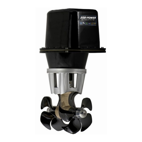
SE120/215T IP
Ignition Protected
thruster assembly
Document id:
Revision:
© Sleipner Motor AS
2651
3
2015
Table of
Contents
Previous
Page
Next
Page
1
2
3
4
5
Advertisement
Table of Contents
Need help?
Do you have a question about the SE120T IP and is the answer not in the manual?
Ask a question
Questions and answers
Related Manuals for Side-Power SE120T IP
Outboard Motor Side-Power SE80/185T Installation And User Manual
Ignition protected thruster assembly (20 pages)
Outboard Motor Side-Power SE 150-215T Installation And User Manual
(28 pages)
Outboard Motor Side-Power SE170/250TC-IP Installation And User Manual
(20 pages)
Outboard Motor Side-Power SE 120/215T Installation And User Manual
(28 pages)
Outboard Motor Side-Power SE120/215T IP Installation And User Manual
Ignition protected thruster assembly, intelligent power control (20 pages)
Outboard Motor Side-Power SE-170 Installation Manual
(28 pages)
Outboard Motor Side-Power SE Series Installation Manual
(28 pages)
Outboard Motor Side-Power SE-60 Installation Manual
(28 pages)
Outboard Motor Side-Power SE100 Installation Manual
(28 pages)
Outboard Motor Side-Power SE120 Installation Manual
(28 pages)
Outboard Motor Side-Power SE 130/250T IP Installation And User Manual
Ignition protected (20 pages)
Outboard Motor Side-Power SE 130 IP Installation And User Manual
Ignition protected thruster assembly (20 pages)
Outboard Motor Side-Power SE-100/185 Installation Manual
(28 pages)
Outboard Motor Side-Power SE-120/215 Installation Manual
(28 pages)
Outboard Motor Side-Power SE-130/250 Installation Manual
(28 pages)
Outboard Motor Side-Power SE-150/215 Installation Manual
(28 pages)
This manual is also suitable for:
Se215t ip
Se120/215t ip
Table of Contents
Print
Rename the bookmark
Delete bookmark?
Delete from my manuals?
Login
Sign In
OR
Sign in with Facebook
Sign in with Google
Upload manual
Upload from disk
Upload from URL


Need help?
Do you have a question about the SE120T IP and is the answer not in the manual?
Questions and answers