Table of Contents
Advertisement
PC2 Series
Service Manual
©2004 All rights reserved. Kurzweil is a product line of Young Chang Co.; Kurzweil is a
trademark of Young Chang Co. All other products and brand names are trademarks or
registered trademarks of their respective companies. Product features and specifications
are subject to change without notice.
Part Number: 910395 Rev. A
Advertisement
Table of Contents

Related Manuals for Kurzweil PC2 Series


Summary of Contents for Kurzweil PC2 Series
- Page 1 PC2 Series Service Manual ©2004 All rights reserved. Kurzweil is a product line of Young Chang Co.; Kurzweil is a trademark of Young Chang Co. All other products and brand names are trademarks or registered trademarks of their respective companies. Product features and specifications are subject to change without notice.
- Page 2 The lightning flash with the arrowhead symbol, within an equilateral triangle is intended to alert CAUTION the user to the presence of uninsulated "dangerous voltage" within the product's RISK OF ELECTRIC SHOCK enclosure that may be of sufficient magnitude to constitute a risk of electric shock to persons. DO NOT OPEN CAUTION: TO REDUCE THE RISK OF ELECTRIC SHOCK, The exclamation point within an equilateral...
- Page 3 Young Chang Distributors Contact the nearest Young Chang office listed below to locate your local Young Chang/Kurzweil representative. A N D Music Corp. P.O. Box 99995 Lakewood, WA 98499-0995 Tel: (253) 589-3200 Fax: (253) 984-0245 Young Chang Akki Co., Ltd.
-
Page 5: Table Of Contents
Contents Young Chang Distributors ............................... iii Chapter 1 Introduction Models ..................................1-1 Notes, Cautions, Warnings ............................. 1-1 PC2/PC2X ..................................1-2 PC2/PC2X Rear Panel ............................. 1-2 Rear Panel Features..............................1-2 PC2/PC2X Front Panel............................1-3 Front Panel Features ..............................1-3 PC2R....................................1-6 PC2R Rear Panel............................... - Page 6 Kurzweil PC2 Series Service Manual Contents Removing the Top Cover ............................3-2 Replacing the Top Cover............................3-2 Removing the Connector Board..........................3-3 Replacing the Connector Board ..........................3-4 Removing the Polyphony Expansion Board (PCX-1) ..................3-5 Replacing the Polyphony Expansion Board (PCX-1)..................3-5 Removing the Engine Board...........................
- Page 7 Kurzweil PC2 Series Service Manual Contents Removing the Slider Board........................... 4-14 Replacing the Slider Board ........................... 4-15 Removing the Engine Board..........................4-15 Replacing the Engine Board ..........................4-17 Removing the Mod Wheel Assembly........................4-17 Replacing the Mod Wheel Assembly ........................4-18 PC2 Keyboard Assembly..............................
- Page 8 Kurzweil PC2 Series Service Manual Contents Hard Reset................................. 5-2 Soft Reset ................................... 5-2 Software Updates ................................5-3 File Formats................................5-3 Installing the Operating System or Setups......................5-3 Installing a New Boot Block ........................... 5-4 Installing Sound ROM Options..........................5-4 Replacing the Battery..............................5-5 PC2 Keyboard Models.............................
- Page 9 Kurzweil PC2 Series Service Manual Contents Front Panel Board, N012400052 ..........................6-5 Connector Board, N012300061 ..........................6-6 LCD Board, N012103800 ............................6-8 Pitch & Mod Wheel Assembly, N012300053 ......................6-8 Slider Board, N012400051 ............................6-9 PC2 ....................................6-9 Final Assembly, N012000150 ..........................6-9 Keyboard Assembly, N215040311 ........................
- Page 10 Kurzweil PC2 Series Service Manual Contents...
-
Page 11: Chapter 1 Introduction
For in-depth descriptions of the many features the PC2 Series instruments include, consult the Musician’s Guide. This chapter also includes a description of the models available in the PC2 Series and a description of the symbols used throughout this manual. -
Page 12: Pc2/Pc2X
Rear Panel Features Power Switch—Rocker switch to turn the power on and off. Power Connector—Keyed four-pin connector to attach the Kurzweil 9VDC power adapter. MIDI Select Switch—Slide switch to select the operation of the MIDI Thru/Out port. This switch is recessed into the rear panel so that it cannot be accidentally changed. -
Page 13: Pc2/Pc2X Front Panel
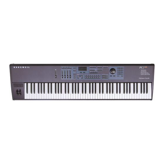
Introduction PC2/PC2X PC2/PC2X Front Panel Figure 1-2 is an illustration of the front panel for the PC2 and the PC2X. Enlargements of sections of this illustration follow, as well as a brief description of the front panel features. Alpha Wheel, Zone Sound Minus (-) and Plus (+) buttons,... - Page 14 Introduction PC2/PC2X Master Volume—Slidepot to adjust the overall volume. Zone Select and Assignable Controllers—The operation of the buttons and sliders in this section depends on which of the three performance modes is active. Their labelling is color- coded to identify their function in each of the performance modes. They are labelled as follows: white–Internal Voices mode, blue–MIDI Setups mode, and orange–KB3 mode.
- Page 15 Introduction PC2/PC2X Sound / Setup Select Effects and Reverb Internal MIDI Voices Setups Mode Piano 1 Piano 2 E Piano 1 E Piano 2 Pop Keys Clavier Organ Brass FX-A Select Wet / Dry Previous Next Mute A Group Group Strings Voices Synths...
-
Page 16: Pc2R
MIDI data. MIDI Select Switch—Slide switch to select the operation of the MIDI Thru/Out port. Power In—Keyed four-pin connector to attach the Kurzweil 9VDC power adapter. PC2R Front Panel Figure 1-8 is an illustration of the front panel for the PC2R. Enlargements of sections of this illustration follow, as well as a brief description of the front panel features. -
Page 17: Front Panel Features
Introduction PC2R Front Panel Features Power/Volume—Push to turn the power on/off and turn it to adjust the volume. Headphones—Standard 1/4” jack to connect headphones. Performance section—The buttons and knobs in this section are multi-function and their operation depends on which performance mode is active (Internal Voices, KB3, or MIDI Setups). Their labelling is color-coded to identify their operation for each of the performance modes. - Page 18 Introduction PC2R Edit Edit / Store Group / Menu Compare Copy Cancel Enter Figure 1-10 Edit section Select the Edit/Store button to enter the edit mode for the current performance mode to edit programs, setups, etc. To save the changes, press the Edit/Store button again to enter the save dialog.
-
Page 19: Chapter 2 Diagnostics
Chapter 2 Diagnostics Diagnostic Tests The following lists the diagnostic tests available for the PC2 Series. • • Read-write • • MABEL • LISA • Sound ROM • ZRAM • MIDI • If a PCX-1 Board is installed, the following tests are also available: •... -
Page 20: Entering Diagnostics
Diagnostics Entering Diagnostics Entering Diagnostics 1. Apply power to the unit. When the message appears in the LCD, Please wait... quickly press and release the Panic button for PC2 keyboard units or the Edit button for PC2R rack units. The LCD should display the following: Main menu Install engine Figure 2-1... -
Page 21: Run Burn-In
Diagnostics Test Results At the completion of a test, whether pass or fail, press the Cancel button to exit the test. Press either the Left of Right cursor button to advance to the next test or another test in the sequence. At the completion of a test, press the Cancel button to return to the test menu. -
Page 22: Description Of Tests
Diagnostics Description of Tests Description of Tests This test checks the software data (engine, boot, and setups) stored in FlashROM on the Engine Board. A failure of this test may indicate a problem with the Flash ROM chip (U5 on the Engine Board), associated circuitry, or the Engine Board. -
Page 23: Zram
Diagnostics Description of Tests ZRAM This test performs a quick read-write of the internal RAM and verifies that the data was successfully written and retained. A failure of this test may indicate a problem with the RAM or the Engine Board. MIDI The MIDI test performs a loop-back of the serial port by sending a 23-byte pattern over the external MIDI link. -
Page 24: Pcx-1 Mabel
Diagnostics Description of Tests PCX-1 MABEL This test performs a read-write of the MABEL registers and verifies that the data written can be read back successfully. A failure of this test may indicate a problem with a MABEL, associated circuitry or the PCX-1 Board. -
Page 25: Pc2R Disassembly/Assembly
Chapter 3 PC2R Disassembly/Assembly Introduction This chapter contains all the procedures for the disassembly and reassembly for the PC2R—as well as instruments with factory-installed or after-market options. Warning: If possible, save all user programs and setups before disassembly. For instructions, refer to Saving User Data in Chapter 5, page 5-1. -
Page 26: Opening The Pc2R
PC2R Disassembly/Assembly Opening the PC2R Opening the PC2R Removing the Top Cover Before you begin disassembly, please be sure that the power is off, and that the AC power adapter and all other cables are disconnected. The top cover is secured to the PC2R with seven screws: three on the top, one on each side, and two on the rear. -
Page 27: Removing The Connector Board
PC2R Disassembly/Assembly Opening the PC2R Removing the Connector Board 1. Following Steps 2– 5, disconnect the cables listed in Table 3-1. Ref. Name Cable Type Destination J301 PC2 Power stranded wire Engine Board J302 PC2R Audio In flat ribbon Engine Board J303 MIDI/CPU flat ribbon... -
Page 28: Replacing The Connector Board
PC2R Disassembly/Assembly Opening the PC2R Replacing the Connector Board 1. Tilt down the inner edge (closest to the Front Panel Assembly) of the Connector Board and heat sink, and place it flat on to the bottom enclosure. 2. Slide the Connector Board and heat sink toward the rear panel so that the jacks and MIDI switch are positioned through their openings in the rear panel. -
Page 29: Removing The Polyphony Expansion Board (Pcx-1)
PC2R Disassembly/Assembly Opening the PC2R Removing the Polyphony Expansion Board (PCX-1) The Polyphony Expansion Board is mounted onto the Engine Board and held in place with four nylon PC board standoffs and a 24-pin female connector on the underside of the board. It is also secured to the bottom enclosure with two screws. -
Page 30: Removing The Engine Board
PC2R Disassembly/Assembly Opening the PC2R Removing the Engine Board 1. If the PC2R you are servicing has a PCX-1 Board installed, remove it following the procedure described on page 3-5. 2. Following Steps 3–6, disconnect the cables listed in Table 3-2. Ref. - Page 31 PC2R Disassembly/Assembly Opening the PC2R Caution: Be sure to look for the marking on the edge of the cable denoting Pin 1 and that you match it correctly with Pin 1 on the board. Make certain that the wires are straight prior to inserting them into the connector and that each wire is correctly inserted into its respective position.
-
Page 32: Front Panel Assembly
PC2R Disassembly/Assembly Front Panel Assembly Front Panel Assembly The Front Panel Assembly consists of the front panel faceplate, a mounting bracket for the front panel boards, and four printed circuit boards. The boards mounted on the Front Panel Assembly are the Right Front Panel, LCD, Left Front Panel, and Headphone/Volume/Power Switch. Removing the Front Panel Assembly Refer to Figure 3-4. -
Page 33: Removing The Front Panel Faceplate
PC2R Disassembly/Assembly Front Panel Assembly Removing the Front Panel Faceplate Note: If the service you are performing only requires that you have access to the front panel boards for component testing, component replacement or installing a replacement board, it is not necessary to remove the front panel faceplate. Refer to the procedure for the front panel board you need to remove and follow the steps described. -
Page 34: Removing The Right Front Panel Board
PC2R Disassembly/Assembly Front Panel Assembly Headphone/Volume/ Power Switch Board Left Front Panel Board Board Right Front Panel Board Figure 3-5 Front panel faceplate screw locations Removing the Right Front Panel Board 1. Remove the Front Panel Assembly, as described on page 3-8. It is not necessary to disconnect all the cables that connect the Front Panel Assembly boards to boards located on the bottom enclosure. -
Page 35: Replacing The Right Front Panel Board
PC2R Disassembly/Assembly Front Panel Assembly Replacing the Right Front Panel Board 1. Place the Right Front Panel Board in position on the mounting bracket and line up the screw holes. Note: Verify that the rotary potentiometers and switch button caps are correctly positioned through their openings in the front panel faceplate. -
Page 36: Replacing The Lcd Board
PC2R Disassembly/Assembly Front Panel Assembly Replacing the LCD Board 1. Place the LCD Board in position over the mounting standoffs on the mounting bracket. 2. Install the two screws that secure the LCD Board to the mounting bracket. 3. Install the screw that secures the front panel faceplate to the Front Panel Assembly. 4. -
Page 37: Replacing The Left Front Panel Board
PC2R Disassembly/Assembly Front Panel Assembly Left Front Panel Board HP/Vol/Pwr Sw Board J603 J604 Circuit side soldered connection Figure 3-6 Left Front Panel and Headphone/Volume/Power Switch Board connection Remove the Left Front Panel Board. Replacing the Left Front Panel Board 1. -
Page 38: Removing The Headphone/Volume/Power Switch Board
PC2R Disassembly/Assembly Front Panel Assembly Removing the Headphone/Volume/Power Switch Board 1. Remove the Front Panel Assembly, as described on page 3-8. It is not necessary to disconnect all the cables that connect the Front Panel Assembly boards to boards located on the bottom enclosure. -
Page 39: Pc2/Pc2X Disassembly/Assembly
Chapter 4 PC2/PC2X Disassembly/Assembly Introduction This chapter contains all the procedures for the disassembly and reassembly of both the 76-note PC2 and the 88-note PC2X—as well as instruments with factory-installed or after-market options. There are five main sections: Opening the PC2/PC2X, Top Enclosure, PC2 Keyboard Assembly, and PC2X Keyboard Assembly. -
Page 40: Opening The Pc2/Pc2X
PC2/PC2X Disassembly/Assembly Opening the PC2/PC2X Opening the PC2/PC2X PC2 Bottom Refer to Figure 4-1. Arrows indicate the locations of the enclosure support wall, endcap and rear panel screws. Keyboard Enclosure support wall screws Access panel Rear panel screws Rear panel *Endcap locking bracket screws Figure 4-1 PC2 bottom enclosure... -
Page 41: Pc2X Bottom
PC2/PC2X Disassembly/Assembly Opening the PC2/PC2X PC2X Bottom Refer to Figure 4-2. Arrows indicate the locations of the enclosure support wall, endcap and rear panel screws. Keyboard Enclosure support wall screws Access panel Rear panel screws Rear panel *Endcap locking bracket screws Figure 4-2 PC2X bottom enclosure Caution: Do not remove the endcap or rear panel screws at this point of the procedure. -
Page 42: Removing The Top Enclosure
PC2/PC2X Disassembly/Assembly Opening the PC2/PC2X Removing the Top Enclosure 1. Depending on the unit you are servicing, follow the procedures described on page 4-2 for the PC2 bottom or page 4-3 for the PC2X bottom. 2. Refer to Figure 4-3. Note: Figure 4-3 is an illustration of the PC2 rear panel. - Page 43 PC2/PC2X Disassembly/Assembly Opening the PC2/PC2X Figure 4-4 Top cover and bottom enclosure Warning: Be sure to have your work surface prepared. This includes placing foam blocks behind the unit. When the top enclosure is removed, place it on the foam blocks to avoid damaging the Alpha Wheel, control panel buttons, and sliders.
-
Page 44: Replacing The Top Enclosure
PC2/PC2X Disassembly/Assembly Opening the PC2/PC2X Replacing the Top Enclosure 1. Position the top enclosure behind the bottom enclosure. 2. Move the top enclosure so that the bottom edge of the rear panel is positioned under the bottom enclosure edge. See Figure 4-4 on page 4-5. Note: Verify that the cables listed in Table 4-1 are lying flat on the bottom enclosure. -
Page 45: Top Enclosure
PC2/PC2X Disassembly/Assembly Top Enclosure Top Enclosure The top enclosure includes five boards: Connector, Front Panel, LCD, Slider, and Engine. The Right and Left Enclosure Support Walls are also included on the top enclosure. Figure 4-5 shows the placement of the enclosure support walls. Figure 4-6 shows the placement of the boards. Left Enclosure Support Wall Right Enclosure Support Wall Figure 4-5... -
Page 46: Removing The Enclosure Support Walls
PC2/PC2X Disassembly/Assembly Top Enclosure Removing the Enclosure Support Walls Left Enclosure Support Wall 1. Remove the four screws that secure the left enclosure support wall to the top enclosure, and remove the left enclosure support wall. Right Enclosure Support Wall 1. - Page 47 PC2/PC2X Disassembly/Assembly Top Enclosure 4. Remove the cable locking clips and disconnect the flat ribbon cables from J304, J306, and J307. Be sure to set the cable locking clips safely aside so that you can install them when you reconnect the cables. Note: The cables used throughout the PC2/PC2X are bundled and routed so that their locations and destinations seem obvious.
-
Page 48: Replacing The Connector Board
PC2/PC2X Disassembly/Assembly Top Enclosure Replacing the Connector Board 1. Hold the Connector Board and position it so that the power switch, LCD Contrast potentiometer, and the rear panel jacks are correctly positioned through the rear panel portion of the top enclosure. 2. - Page 49 PC2/PC2X Disassembly/Assembly Top Enclosure Ref. Name Cable Type Destination J601 IBBB flat ribbon Button Board/Wheel Assembly J602 FP Bridge flat ribbon Slider Board Table 4-3 Front Panel Board cables 4. The flat ribbon cables connected to J601 and J602 use wire trap connectors. The shielding has been removed from the end of these cables to expose the wires.
-
Page 50: Replacing The Front Panel Board
PC2/PC2X Disassembly/Assembly Top Enclosure The LCD is mounted onto a bezel that is secured to the Front Panel Board with small pegs that snap into holes on the Front Panel Board. Removing the LCD requires cutting the tie wraps that bundle the LCD cables to cable mounts positioned along the rear panel. It is not necessary to remove the LCD from the unit. -
Page 51: Removing The Lcd Board
PC2/PC2X Disassembly/Assembly Top Enclosure Removing the LCD Board 1. Follow the procedure described on page 4-8 to remove the right enclosure support wall. 2. Disconnect the stranded wire from location J405 on the Engine Board. 3. Remove the cable locking clip and disconnect the flat ribbon cable from J406 on the Engine Board. -
Page 52: Replacing The Polyphony Expansion Board (Pcx-1)
PC2/PC2X Disassembly/Assembly Top Enclosure Replacing the Polyphony Expansion Board (PCX-1) 1. Place the PCX-1 Board over the four standoffs. This should properly position the 24-pin connector over the 24-pin header on the Engine Board. 2. Press the PCX-1 Board down, securing the 24-pin connector, and snapping the board onto the standoffs. -
Page 53: Replacing The Slider Board
PC2/PC2X Disassembly/Assembly Top Enclosure Caution: Each switch button cap uses a set of small pegs to mount the cap to the Slider Board. The button caps are mounted individually or in clusters. If a cap becomes separated from the board, be careful that a peg is not inadvertently broken. Replacing the Slider Board 1. - Page 54 PC2/PC2X Disassembly/Assembly Top Enclosure Ref. Name Cable Type Destination J402 PC2 PWR stranded wire Connector Board J403 MIDI & CPU flat ribbon Connector Board J405 Backlight stranded wire LCD Board J406 flat ribbon LCD Board J412 PC2 Audio Out flat ribbon Connector Board Table 4-4 Engine Board cables...
-
Page 55: Replacing The Engine Board
PC2/PC2X Disassembly/Assembly Top Enclosure Replacing the Engine Board 1. Place the Engine Board in position on the top enclosure. 2. Align the center screw hole on the front panel edge with the thread marks in the extrusion and install the screw that secures the front panel edge. See Figure 4-10. 3. -
Page 56: Replacing The Mod Wheel Assembly
PC2/PC2X Disassembly/Assembly Top Enclosure 4. The flat ribbon cables connected to the two boards on the Mod Wheel Assembly use wire trap connectors. The shielding has been removed from the end of these cables to expose the wires. The wires are inserted directly into these connectors. From the Mod Wheel Assembly, disconnect the flat ribbon cable from J201 on the Wheels Board. -
Page 57: Pc2 Keyboard Assembly
PC2/PC2X Disassembly/Assembly PC2 Keyboard Assembly PC2 Keyboard Assembly This section describes the removal and replacement of the PC2 (76-note) Keyboard Assembly. See page 4-26 for the corresponding procedures for the PC2X (88-note) Keyboard Assembly. Removing the PC2 Keyboard Assembly The following procedure assumes that the PC2 is open and that you have followed the instructions on page 4-4 to remove the top enclosure. -
Page 58: Replacing The Pc2 Keyboard Assembly
PC2/PC2X Disassembly/Assembly PC2 Keyboard Assembly 7. Lift the Mod Wheel Assembly and disconnect the Aftertouch flex cable. This cable has nylon reinforced tape securing it to the bottom enclosure. Peel back the tape from one side to free the cable. 8. -
Page 59: Disconnecting The Pc2 Keyboard
PC2/PC2X Disassembly/Assembly PC2 Keyboard Assembly Disconnecting the PC2 Keyboard Follow this procedure if you are merely replacing one or more keys. 1. Refer to Figure 4-11. 2. Tilt the PC2 up and remove the four keyboard rear screws, then lay the PC2 flat on your work surface. -
Page 60: Removing Keys
PC2/PC2X Disassembly/Assembly PC2 Keyboard Assembly Removing Keys The following procedure assumes you have removed the top enclosure from the PC2. 1. Follow the procedure for removing the keyboard (page 4-19) or disconnecting the keyboard (page 4-21). 2. The following diagrams illustrate the outlines of the natural and sharp keys and the locations and functions of the components described in the following procedures. -
Page 61: Natural/White Keys
PC2/PC2X Disassembly/Assembly PC2 Keyboard Assembly Natural/White Keys 1. Each key has a spring located at the rear of the key. Using needle-nose pliers, slightly pull up the top portion of the spring to release it from the key. Caution: Be careful not to pull up too much, which could damage the spring. 2. -
Page 62: Replacing A Key
PC2/PC2X Disassembly/Assembly PC2 Keyboard Assembly Replacing a Key The following instructions apply to both natural and sharp keys. Note: Always replace a sharp key before replacing the adjacent natural keys. 1. Place the key on the keyboard chassis and lower the key into position. 2. -
Page 63: Removing The Keyboard Contact Strips
PC2/PC2X Disassembly/Assembly PC2 Keyboard Assembly Removing the Keyboard Contact Strips 1. Place the keyboard upside down on a flat soft surface. Be sure that the keys are resting on a soft surface to avoid scratching or other damage. 2. Follow the procedure for removing the Bass and Treble Keyboard Contact Boards on page 4-24. -
Page 64: Pc2X Keyboard Assembly
PC2/PC2X Disassembly/Assembly PC2X Keyboard Assembly PC2X Keyboard Assembly Removing the PC2X Keyboard Assembly The following procedure assumes that the PC2X is open and that you have followed the instructions to remove the top enclosure. 1. The keyboard is secured to the bottom enclosure using ten screws. Refer to Figure 4-16 for the position of the screws. -
Page 65: Replacing The Pc2X Keyboard Assembly
PC2/PC2X Disassembly/Assembly PC2X Keyboard Assembly Replacing the PC2X Keyboard Assembly 1. Place the keyboard on the bottom enclosure. Be sure that the flat ribbon cables from the keyboard are correctly positioned to connect them to the Connector Board. Note: If you have disconnected the Bass and Treble ends of the flat ribbon cables from the keyboard contact boards during service, be sure that you have reconnected them and secured them with tape. -
Page 66: Natural/White Key
PC2/PC2X Disassembly/Assembly PC2X Keyboard Assembly Natural/White Key Pivot location Key spring location Strikes the front and rear key Hooks under the front of the keyboard chassis contact on key depression Mounts through the keyboard chassis Figure 4-17 Natural/white key, 88-note keyboard Pivot location Key spring... -
Page 67: Sharp/Black Keys
PC2/PC2X Disassembly/Assembly PC2X Keyboard Assembly Insert the screwdriver here Insert a 3mm dia. dowel into the spring and push down slightly. Then move the top of the dowel toward the front of the keyboard to remove the spring from the hook. Pivot Keyboard chassis section... -
Page 68: Replacing A Key
PC2/PC2X Disassembly/Assembly PC2X Keyboard Assembly Replacing a Key 1. The following instructions apply to both natural and sharp keys. Note: Always replace a sharp key before replacing the adjacent natural keys. 2. Hook the front end of the key under the keyboard chassis. 3. -
Page 69: Replacing The Bass Contact Board
PC2/PC2X Disassembly/Assembly PC2X Keyboard Assembly Replacing the Bass Contact Board 1. Position the Bass Contact Board on the keyboard chassis. Be sure that the rubber key contacts line up properly through the holes in the keyboard chassis. 2. Install the 22 screws that secure the board to the keyboard chassis. 3. -
Page 70: Replacing The Keyboard Contact Strips
PC2/PC2X Disassembly/Assembly PC2X Keyboard Assembly Replacing the Keyboard Contact Strips 1. Position the contact strip on the Keyboard Contact Board that you are servicing. Note: Be sure that the deeper indentation is positioned toward the rear of the key. 2. Line up the contact strip mounting pegs with their respective mounting holes on the keyboard contact board. -
Page 71: Replacing A Key Weight
PC2/PC2X Disassembly/Assembly PC2X Keyboard Assembly Replacing a Key Weight 1. Each key weight has a strip of red felt attached with pliable adhesive. Be sure the red felt extends onto the upper surface of the top of the key weight. 2. - Page 72 PC2/PC2X Disassembly/Assembly PC2X Keyboard Assembly 4-34...
-
Page 73: Chapter 5 Troubleshooting
Chapter 5 Troubleshooting Introduction Cables, Connectors Flat Ribbon Cables All flat ribbon cables with connectors are keyed, and therefore cannot be reversed. Most flat ribbon cables have locking cable clips. Be sure to reapply the clips when connecting cables. Flat ribbon cables that connect to picoflex connectors do not have locking cable clips. -
Page 74: Boot Block
Troubleshooting Boot Block Boot Block Use the PC2’s Boot Loader to enter Diagnostics or perform a Hard Reset to the unit. You can also install operating system updates and ROM objects into Flash ROM. Entering the Boot Block Apply power to the unit. When the message appears in the LCD, quickly Please wait... -
Page 75: Software Updates
Troubleshooting Software Updates Software Updates A computer with a MIDI interface and sequencer is necessary to transfer software to your PC2 units MIDI Sysex. File Formats Software upgrades are stored as standard MIDI files. Filenames are in the format PC2XVV.MID, where X is the software block and VVV is the version number (V.VV). -
Page 76: Installing A New Boot Block
Troubleshooting Software Updates Installing a New Boot Block Warning: This procedure performs a hard reset. All user programs and setups will be erased. Before continuing, be sure to save all user programs and setups. 1. Connect a MIDI cable from the MIDI Out port of the computer interface or sequencer to the MIDI In port on the PC2. -
Page 77: Replacing The Battery
Troubleshooting Replacing the Battery Replacing the Battery The PC2 uses a flat three volt Lithium coincell battery. When the battery voltage runs low, the unit boots up with a low battery message. Note: The battery voltage can be checked at anytime using the Scanner Diagnostics. See page 5-7 for more information. -
Page 78: Pc2R Rack Models
Troubleshooting Replacing the Battery PC2R Rack Models Accessing the Battery 1. Remove the seven screws that secure the top cover. 2. Slide the top cover back from the Front Panel Assembly to release the top cover from the bottom enclosure, and place the top cover safely aside to avoid damage. 3. -
Page 79: Scanner Tests
Troubleshooting Scanner Tests Scanner Tests PC2R Rack Models The Scanner Tests for the PC2R rack model include separate tests for the front panel buttons and LEDs, rotary potentiometers including Knobs A–D and Volume, and the Alpha Wheel. To enter the Scanner Tests, first turn on the PC2R. Once the PC2R is on and ready to play, simultaneously hold down the three buttons located in the top row of the Modes section (Internal Voices, KB3 and MIDI Setups). -
Page 80: Pc2 Keyboard Models
Troubleshooting Scanner Tests PC2 Keyboard Models The Scanner Tests for the PC2 keyboard models include separate tests for the front panel buttons and LEDs, front panel sliders including the Master Volume slider, the Alpha Wheel, the Mod and Pitch wheels, the keyboard, and the pedals. To enter the Scanner Tests, first turn on the PC2. -
Page 81: Wheels
Troubleshooting Scanner Tests Wheels To test the pitch and mod wheels, move the wheel up and down. An example of the expected test results for the pitch wheel follows (your results may vary slightly): At bottom: PITCH WHEEL At center: PITCH WHEEL At top: PITCH WHEEL Keyboard To test the keyboard, press any key. -
Page 82: Power Problems
Troubleshooting Power Problems Power Problems Dead 1. Before opening the unit, verify the following: • The AC outlet is supplying power. • The AC adapter is properly connected to the unit. 2. Check the power switch, power jack and AC adapter. 3. -
Page 83: Front Panel Problems
Troubleshooting Front Panel Problems Front Panel Problems LCD not lit 1. Check the LCD contrast potentiometer. Turn the pot to see if there is any change. Note: If you are servicing a PC2R rack unit, the LCD Contrast is located on the front panel. -
Page 84: Keyboard Problems
Troubleshooting Keyboard Problems Keyboard Problems Dead Keyboard 1. Check the flat ribbon cables connecting the keyboard Bass and Treble Contact Boards to the Connector Board, locations J306 and J307. Be certain that the cables are not loose or damaged. 2. Disconnect and reseat the cables. 3. -
Page 85: Pc2R Interconnect Diagram
Troubleshooting PC2R Interconnect Diagram PC2R Interconnect Diagram Left Front Right Front Panel Board Panel Board J604 J603 J602 J601 FP Bridge 2 FP Bridge FP Bridge Front Panel Hp/Vol/Pwr Sw Board FP Bridge 2 Vol/Pwr/Hp Connector Board J322 J301 J303 J304 J302 Vol/Pwr/Hp... -
Page 86: Pc2 Interconnect Diagram
Troubleshooting PC2 Interconnect Diagram PC2 Interconnect Diagram Button Board J701 J601 J101 Slider Front Panel IBBB Slider J604 Board Board Front Panel J602 J102 FP Bridge FP Bridge J402 J412 J406 PC2 PWR Engine Audio Out J405 J408 Board Backlight J410, Expansion Sound ROM 1 J409, Expansion Sound ROM 0 J403... -
Page 87: Parts Lists
Parts Lists Introduction The parts lists included in this chapter cover all models of the PC2 series. Some printed circuit boards and assemblies are used in more than one model. Therefore, the parts lists on the following pages are listed under these headings:... -
Page 88: Pc2R Printed Circuit Boards And Assemblies
Parts Lists Introduction PC2R Printed Circuit Boards and Assemblies Part No. Description Page N012000153 Final Assembly page 6-16 N012103802 LCD Board page 6-15 N012300040 Connector Board page 6-13 N012300051 Engine Board page 6-3 N012300070 Front Panel Assembly page 6-14 N012300080 Left Front Panel Board page 6-14 N012300090... -
Page 89: Pc2R/Pc2/Pc2X
Parts Lists PC2R/PC2/PC2X PC2R/PC2/PC2X Engine Board, N012300051 Part No. Description Qty. Reference Designation N035040201 BATTERY HOLDER TOSHIBA (BV-32) PC-88 J411 N041010401 SHUNTS JUMPER 2mm DIGI-KEY SPE1302-ND @JP1 N041021264 SOCKET SIMM 22.5D TIN 64P LEFT METAL J409, 410 N041025308 HEADER .156” SP 8P (09-65-2088) J402 N041030040 HEADER 2mm SQR 3P R/A SAMTEC... - Page 90 Parts Lists PC2R/PC2/PC2X Part No. Description Qty. Reference Designation N052007406 CAP CER N90 2200PF 50V 5% 1206 C71, 72, 75, 76 N052007503 CAP CER X7R 0.1UF 50V 10% 1206 C5, 615-38, 41-43, 47, 60-63, 69, 70, 73, 74, 77-81, 86, 87, 91 N052007809 CAP CER NPO 100PF 50V 5% 0603 N052007833...
-
Page 91: Pc2/Pc2X
Parts Lists PC2/PC2X PC2/PC2X Front Panel Board, N012400052 Part No. Description Qty. Reference Designation N032009401 FRONT PANEL PCB SUPPORT BRACKET PC-88 N035026011 BUTTON SM W/LED (3GANG) N035026012 BUTTON SM W/LED RED PC2/X N035026101 BUTTON LG W/LED PC-88 N035026141 BUTTON LG W/LED (1,2,3,4) PC2/X N035026142 BUTTON LG W/LED (5,6,7,8) PC2/X N035026143... -
Page 92: Connector Board, N012300061
Parts Lists PC2/PC2X Part No. Description Qty. Reference Designation N051100157 RES CF 10KΩ 5% 1/8W R9-26 N052001204 CAP CER MONO Z5U .1UF 50V 20% .3AX C2-4 N054000801 TRANSISTOR PN2222 TO-92 Q1-7 N054001201 TRANSISTOR PNP KTA1271(KSA643CY) TO-9 Q8-17 N061000301 IC LOGIC 74LS145 DIP16-300 N061014001 IC LOGIC 74HC541 DIP20 N061020501... - Page 93 Parts Lists PC2/PC2X Part No. Description Qty. Reference Designation N051101721 RES CF 270Ω 5% 1/8W 1206 R6, 83 N051101724 RES 470 5% 1/8W 1206 R18, 117 N051101730 RES CF 1.0KΩ 5% 1/8W 1206 R87, 120, 148 N051101734 RES TF 1.5KΩ 5% 1/8W 1206 N051101738 RES CF 2.2KΩ...
-
Page 94: Lcd Board, N012103800
Parts Lists PC2/PC2X LCD Board, N012103800 Part No. Description Qty. Reference Designation N013040112 CABLE ENGINE TO LCD 14P RIBBON N013042601 CABLE ENGINE TO LCD BACKLIGHT 2P PC2/X N045010302 LCD UC-20212BLANO SAMSUNG PC-88/MX Pitch & Mod Wheel Assembly, N012300053 Part No. Description Qty. -
Page 95: Slider Board, N012400051
Parts Lists Slider Board, N012400051 Part No. Description Qty. Reference Designation N035026158 BUTTON LG W/LED (ZONE1,3,4) PC2 N035026321 SLIDER KNOB PC-88 N035026411 SLIDER BEZEL PC-88 N039000701 SLIDE VOLUME FELT 0.3TX12X70 N041032307 CONN WIRE TRAP 2.00mmSP 7P (52147-0710) J101 N041032308 CONN WIRE TRAP 2.00mmSP 8P (52147-0810) J102 N043003703 SW TACT SPST 6mmX6mm 160GF ALPS SKHWAC... -
Page 96: Keyboard Assembly, N215040311
Parts Lists Part No. Description Qty. Reference Designation N032038813 CLAMP PCB PC2/X N032038814 BRACKET CLAMPING ENCLOSURE TOP PC2/X N032038815 BRACKET LOCKING ENDCAP PC2/X N032038950 SPACER (BLK) N032059011 PLATE COVER PCB PC2/X N035020711 KNOB ENCODER 52 N035026511 LCD DISPLAY LENS PC-88 N039004322 CABLE MOUNT BASE (DAMD-10) N125223408... -
Page 97: Pc2X
Parts Lists PC2X PC2X Final Assembly N012000151 Part No. Description Qty. Reference Designation E207407181 DOUBLE SIDE TAPE 3M(5MMX50M)#4670.01 N013030951 CABLE TIE N013041601 CABLE SLIDER TO FRONT PANEL 8P PC2/X N013041701 CABLE SLIDER TO CONNECTOR BD 7P PC2/X N013041801 CABLE ENGINE TO CONNECTOR BD 10P PC2/X N013041901 CABLE ENGINE TO CONNECTOR BD 5P PC2/X N013042001... -
Page 98: Keyboard Assembly, N215040413
Parts Lists PC2X Part No. Description Qty. Reference Designation N039040004 BUMPON 3M N052001022 ADAPTER N035027013 CHECK PITCH & MOD WHEEL N032033713 ENDCAP LEFT N032033813 ENDCAP RIGHT N125223408 TAPPING SCREW-2 BH 3X8 BLK (PLASTIC) FOR ENDCAPS N125223410 TAPPING SCREW-2 BH 3X10 AN (PLASTIC) N215040413 KEYBOARD TP-10MDF AFT (ABS) Keyboard Assembly, N215040413... -
Page 99: Pc2R
Parts Lists PC2R PC2R Connector Board, N01230004 Part No. Description Qty. Reference Designation RES TF 7.5KΩ 5% 1/8W 1206 N041006503 CONN PWR JACK 4P W/SHIELD UNITOP J321 N041021903 JACK PHONE RCA TYPE TA PCMT J300 N041025308 HEADER .156" SP 8P (09-65-2088) J301 N041030326 HEADER .1"... -
Page 100: Front Panel Assembly, N012300070
Parts Lists PC2R Part No. Description Qty. Reference Designation N053000703 DIODE RECT GP SMT 1A S1A SMA 1N4001 1206 D14-15, 17, 22 N053000802 DIODE SWITCH 1N4148 SMT DL-35 D13, 21 N054000802 TRANSISTOR MMBT2222L SOT-23 Q7, 9, 18 N054002906 TRANSISTOR MMBT2907L SOT-23 Q4, 8, 12-13 N054010301 TRANSISTOR NPN KSC2331-Y... -
Page 101: Right Front Panel Board, N012300090
Parts Lists PC2R Right Front Panel Board, N012300090 Part No. Description Qty. Reference Designation N041030036 HEADER 16P PICOFLEX MOLEX 90325-0016 J602 N041030326 HEADER .1" SP DUAL ROW 26P (057-026-153) J601 N043003704 SW TACT SPST 6mmX6mm 160gf ALPS SKHHDA S1-14 N045010111 LED T1 RED HI EFF DIFFUSED LTL-4221 D1-8 N045010610... -
Page 102: Final Assembly, N012000153
Parts Lists PC2R Final Assembly, N012000153 Part No. Description Qty. Reference Designation N013041802 CABLE ENG TO CONN BD 10P PC2R 160mm N013042202 CABLE ENG TO CONN BD POWER PC2R 200mm N032062700 FRONT PANEL N039040001 BUMPON (BLACK) 3M SJ-5508 N052001021 ADAPTER (YCA) PC2 N013042801 CABLE CONN TO HEADPHONE PC2R 270mm N013042901... -
Page 103: Schematics
Chapter 7 Schematics Description Page No. Engine Board–Microprocessor (page 1 of 5) page 7-3 Engine Board–Master/Slave Mabels (page 2 of 5) page 7-4 Engine Board–Lisa F/X 128Ch Option, Clocks (page 3 of 5) page 7-5 Engine Board–Sound ROM, Uart, Glue, Decoupling (page 4 of 5) page 7-6 Engine Board–Audio Channel, Muting Control (page 5 of 5) page 7-7... -
Page 105: Engine Board-Microprocessor
Chapter 7 Engine Board–Microprocessor (page 1 of 5) Kurzweil PC2 Series Service Manual CD[15:00] {2-C1,3-A1,4-C6} CA[20:00] {2-A1,3-A1,4-B5} BUVDD 1.3K MC68331CPV25 J404 0.1 uF 0.1 uF 47uF 35V PE2/AVEC_L PE7/SIZ1 SIZ1 {4-C6} DSACK1 {2-A1,3-A1} PE1/DSACK1_L VCC1 PE6/SIZ0 SIZ0 {4-C6} 1M/2MX16 FLASH ROM... -
Page 106: Engine Board-Master/Slave Mabels
Kurzweil PC2 Series Service Manual Engine Board–Master/Slave Mabels (page 2 of 5) KISI {3-D8} DSACK1 {1-A1,3-A1} CWE {1-A3,C4,C5;3-A1;4-C6} KISO {3-A1} CA[20:00] {1-A8,3-A1,4-B5} TOPO {3-A1,D6} SMWE {4-D1} CLK20 {3-D8,4-D6} CLK25 {1-C1,3-D8,5-C1} RESET {1-B4,D5;3-D1;4-D6;5-C1} DACBCLK {5-D1} JTAGMODE DACL_R {5-D1} JTAGIN JTAGOUT DACDATA {5-D1}... -
Page 107: Engine Board-Lisa F/X 128Ch Option, Clocks
Engine Board–Lisa F/X 128Ch Option, Clocks (page 3 of 5) Kurzweil PC2 Series Service Manual LISA DECOUPLING CAPS NEAR VCC PINS, ONE CAP ON EACH SIDE KISO 3V ONLY DECOUPLING CAPS NEAR PINS 1 AND 21 3VCC TOPO {2-A8} SMRAS... -
Page 108: Engine Board-Sound Rom, Uart, Glue, Decoupling
Kurzweil PC2 Series Service Manual Engine Board–Sound ROM, Uart, Glue, Decoupling (page 4 of 5) DECOUPLING 0.1 uF 0.1 uF 0.1 uF 0.1 uF 0.1 uF 0.1 uF 0.1 uF 0.1 uF 0.1 uF 0.1 uF 0.1 uF 0.1 uF... -
Page 109: Engine Board-Audio Channel, Muting Control
Engine Board–Audio Channel, Muting Control (page 5 of 5) Kurzweil PC2 Series Service Manual +12V +12V +VBAT BUVDD 5600pF 5% NPO J411 0.1 uF 0.1 uF 10UF NE5532 487, 1%, 1/16W 499, 1%, 1/16W 47uF 35V 453, 1%, 1/16W BAS40... -
Page 110: Front Panel And Ibbb Board (Keyboard Models)-Fp Buttons And Leds (Page 1 Of 2
Kurzweil PC2 Series Service Manual Front Panel and IBBB Board (keyboard models)–FP Buttons and LEDs (page 1 of 2) 74HC145 COL0 COL1 COL2 COL3 Legend COL4 Sound/Setup/Select COL5 top row COL6 COL7 2SA1271 2SA1271 2SA1271 2SA1271 2SA1271 2SA1271 2SA1271 2SA1271... -
Page 111: Front Panel And Ibbb Board (Keyboard Models)-Ibbb Buttons And Leds (Page 2 Of 2
Front Panel and IBBB Board (keyboard models)–IBBB Buttons and LEDs (page 2 of 2) Kurzweil PC2 Series Service Manual J701 IBBB LEDROW0 LEDROW1 TACT SWROW0 SWROW1 COL4 TACT YOUNG CHANG CO., LTD. Reproduction without the express written consent of Young Chang Co., Ltd. is prohibited. -
Page 112: Connector Board (Keyboard Models)-Scanner (Page 1 Of 3
Kurzweil PC2 Series Service Manual Connector Board (keyboard models)–Scanner (page 1 of 3) PWRUPRST {3-A8} RESET {3-B1} INTMIDIRxD {2-B8} TOUCHSENS {2-D5} INTMIDITxD {2-B8} IRQ {2-C8} +VBAT DAC2 DAC1 J308 WHEELS +5Vref {2-A1,C3} M37451 P[37] +5VREF P[36] RESETOUT WHEEL1 TxD/ P[35]... -
Page 113: Connector Board (Keyboard Models)-Digital Interface (Page 2 Of 3
Connector Board (keyboard models)–Digital Interface (page 2 of 3) Kurzweil PC2 Series Service Manual J320 MIDI Use either U6 or U7 AES XFRMR +5Vref {1-A1} OUT/THRU 270 5% 2.2K PC410 J300 MMBT2907 SPDIF OUT LL4148 56 5% R106 LL4148 1000pF... -
Page 114: Connector Board (Keyboard Models)-Power Supply/Audio (Page 3 Of 3
Kurzweil PC2 Series Service Manual Connector Board (keyboard models)–Power Supply/Audio (page 3 of 3) +12V +17V 78M12 74HCU04 PWRUPRST {1-A8} J301 Switch is in ON Position 1000uF, 25V 0.1uF 100uF 16V 0.1uF PWRUPRST BUVdd +12V PC88II PWR MUTE +12V AGND... -
Page 115: Slider Board (Keyboard Models)-Sliders
Slider Board (keyboard models)–Sliders Kurzweil PC2 Series Service Manual J102 1N4148 1N4148 1N4148 ZONE 1 ZONE 2 ZONE 3 ZONE 4 FP BRIDGE 1N4148 LEDROW1 LEDROW2 TACT TACT TACT TACT SWROW COL0 COL1 COL2 COL3 GREEN DUAL COLOR DUAL COLOR... -
Page 116: Right Front Panel Board (Rack Models)-Fp Buttons And Leds (Page 1 Of 2
Kurzweil PC2 Series Service Manual Right Front Panel Board (rack models)–FP Buttons and LEDs (page 1 of 2) 74HC145 COL1 PHASEA COL2 COMMON COL3 PHASEB SW ROTARY COL6 MMBT2907 MMBT2907 MMBT2907 MMBT2907 MMBT2907 MMBT2907 COL7 J602 COL9 Front Panel Bridge... -
Page 117: Left Front Panel Board (Rack Models)-Controllers, Fp Buttons And Leds (Page 2 Of 2
Left Front Panel Board (rack models)–Controllers, FP Buttons and LEDs (page 2 of 2) Kurzweil PC2 Series Service Manual ROWDRIVERPOWER 0.1uF 50V 20% MMBT2222A J603 Front Panel Bridge DUAL COLOR DUAL COLOR DUAL COLOR DUAL COLOR DUAL COLOR RDRPWR DGND... -
Page 118: Connector Board (Rack Models)-Scanner (Page 1 Of 3
Kurzweil PC2 Series Service Manual Connector Board (rack models)–Scanner (page 1 of 3) +VBAT RESET {3-C1} PWRUPRST {3-A8} INTMIDIRxD {2-C7} INTMIDITxD {2-C7} IRQ {2-C7} DAC2 DAC1 0.1uF M37451 P[37] P[36] RESETOUT UNUSED TxD/ P[35] AIN[7] RxD/ P[34] R144 RP11 AIN[6]... -
Page 119: Connector Board (Rack Models)-Digital Interface (Page 2 Of 3
Connector Board (rack models)–Digital Interface (page 2 of 3) Kurzweil PC2 Series Service Manual J320 MIDI OUT/THRU Use either U6 or U7 AES XFRMR 270 5% PC410 J300 SPDIF OUT 56 5% R106 LL4148 1000pF 1000pF 1000pF R102 56 5% 0.1uF... -
Page 120: Connector Board (Rack Models)-Power Supply/Audio (Page 3 Of 3
Kurzweil PC2 Series Service Manual Connector Board (rack models)–Power Supply/Audio (page 3 of 3) +12V DPDT +17V 78M12 74HCU04 PWRUPRST {1-A8} J301 1000uF, 25V 0.1uF 100uF 16V 0.1uF PWRUPRST BUVdd +12V MUTE +12V AGND J322 ~17V -12V 79L12ACM 5V_DIG 0.1uF... -
Page 121: Power/Volume/Headphone Board (Rack Models)
Power/Volume/Headphone Board (rack models) Kurzweil PC2 Series Service Manual Power sw / Volume control 14VAC Do not connect these pins 14VACSW 9VDC 9VDCSW +5Vref DGND LEFT RIGHT AGND PC2R FRONT PANEL VOL/PWR/HPhones Headphone Front Panel Bridge 2 +5vref AVSS YOUNG CHANG CO., LTD. - Page 122 Kurzweil PC2 Series Service Manual 7-20...
- Page 123 Kurzweil PC2 Series Service Manual Alpha Wheel Test Cables, keyboard models scanner tests, PC2 5-8 Connector Board 4-8 scanner tests, PC2R 5-7 Engine Board 4-16 Assembly instructions, 76-note Keyboard Assembly Front Panel Board 4-11 connecting the keyboard 4-21 Cables, rack models...
- Page 124 Kurzweil PC2 Series Service Manual top cover and bottom enclosure 4-5 top enclosure, board locations 4-7 Final Assembly top enclosure, enclosure support wall locations 4-7 parts list, 76-note keyboard models 6-9 Diagram, rack models parts list, 88-note keyboard models 6-11...
- Page 125 Kurzweil PC2 Series Service Manual diagram, key weights 4-32 diagram, keyboard models 1-2, 4-4 key spring, diagram 4-29 diagram, rack models 1-6 natural/white keys description 4-28 features, keyboard models 1-2 removing a key weight 4-32 features, rack models 1-6 removing contact strips 4-31...
- Page 126 Kurzweil PC2 Series Service Manual Young Chang Distributors iii ZRAM: diagnostic test 2-5...
Need help?
Do you have a question about the PC2 Series and is the answer not in the manual?
Questions and answers