
Related Manuals for Wohler iAM-AUDIO-2 PLUS


Summary of Contents for Wohler iAM-AUDIO-2 PLUS
-
Page 1: User Guide
PLUS 2RU Multi-Channel Audio Monitor User Guide Part Number 821808-1, Revision A... - Page 2 In no event will Wohler Technologies, Inc. be liable for direct, indirect, special, incidental, or consequential damages resulting from any defect in the hardware, software, or its documentation, even if advised of the possibility of such damages.
-
Page 3: Table Of Contents
TABLE OF CONTENTS Table of Contents User Guide ..................1 TABLE OF CONTENTS ................3 Table of Contents ................... 3 CHAPTER 1: Installation ............... 6 Introduction ....................6 Overview .................... 6 Safety ......................6 Instructions ..................6 Safety Symbols ..................7 Mounting..................... - Page 4 Factory Reset ..................38 System Details................... 39 CHAPTER 3: Technical Info ............... 40 CHAPTER 4: The iAM-AUDIO-2 PLUS Web GUI ........45 Web Browser / Control Device................ 45 First Time IP Assignments ................45 Peer-to-Peer Connection..............45 Network Connection................46 Network Setup.....................
- Page 5 Updating an iAM-AUDIO-2 PLUS Remotely ............80 Updating Multiple Units Remotely ..............82 APPENDIX B: Dante Network Setup ............. 85 Introduction ....................85 What is in the iAM-AUDIO-2 PLUS for Dante? ........... 86 Dante Device Setup ................... 87 Dante Clock Selection ................... 88 Channel Names....................
-
Page 6: Chapter 1: Installation
Loudness meters. Any channels (or channel pairs) from any audio/video source stream may be monitored. The iAM-AUDIO-2 PLUS includes two 3G SDI inputs and it can monitor audio from them. Optional modules will allow decoding of an additional SDI input, Dolby, MADI, AES3, Dolby D, DD+, E, SMPTE 2110, SMPTE 2022-6, and AES streams. -
Page 7: Safety Symbols
10. Refer all servicing to qualified service personnel. Servicing will be required under all of the following conditions: a. The equipment has been damaged in any way, such as when the power- supply cord or plug is damaged. b. Liquid had been spilled or objects have fallen onto the equipment. c. -
Page 8: Sympathetic Vibration
Sympathetic Vibration Sympathetic vibration from other equipment (cables, etc.) in the rack may be serious enough to interfere with the unit’s sound quality. If you experience sympathetic vibrations, use thin card stock, felt, foam, or weather-stripping between the vibrating surfaces. Tie loose cables securely with cable ties. Mechanical Bracing The 2RU chassis is securely attached to the front panel. -
Page 9: Chapter 2: Local Operation
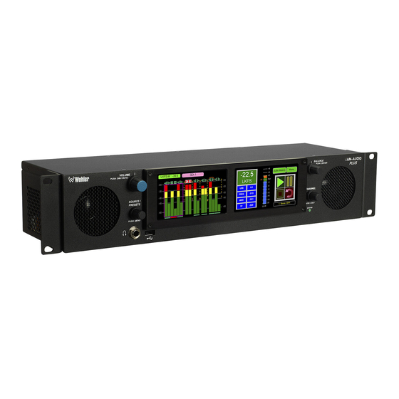
CHAPTER 2: Local Operation Operation The iAM-AUDIO-2 PLUS can be operated easily and simply from controls on its front panel, as described in this chapter. It may be accessed remotely in two ways, via the Wohler Web GUI for administrative purposes or by third party equipment via Application Programming Interface (API) commands. - Page 10 amplifiers. There are two (left/right) speakers. The speaker response may be adjusted with tone controls in the Speaker Options menu. Refer to the Menu / Option Touchscreen section of Chapter 2. 4. Headphone Jack: A 1/4" jack for an optional headphone is provided on the front panel.
-
Page 11: Rear Panel
The rear panel is shown in Figure 2-2. Figure 2-2: iAM-AUDIO-2 PLUS Rear Panel Layout Power Connection: The iAM-AUDIO-2 PLUS receives power from an AC inlet, which is a standard IEC receptacle for 100 to 240 VAC ±10%, 50/60 Hz power connection. Four regional AC power cords, supplied according to shipping region, are available. - Page 12 pass through. A software license must be installed for this input to function. Refer to the System Setup section in Chapter 4 and to Figure 4-17 to install software licenses. 5. MADI Fiber SFP: (optional) This input module accepts an optical AES10 64-channel MADI input signal at 48 kHz sample rate.
- Page 13 . The Analog Inputs are standard on the Left Right iAM-AUDIO-2 PLUS. Refer to Figure 2-4 for the pinout of this connector. Figure 2-4: Analog XLR-F Output Connections 10. Analog Outputs: These male XLR connectors provide two balanced analog outputs: .
- Page 14 Option card. The source of these signals is the monitored audio channels as shown on meters 1 - 8. Tascam cables may be used, and can be purchased by contacting Wohler Sales. Refer to Figure 2-6 for the pinout of this connector.
-
Page 15: Sfp-2022-6 / Sfp-2110 Address Setup
Figure 2-7 illustrates the network connections they need. Figure 2-7: SFP-2022-6 and SFP2110 Network Diagram The optional SFP-2022-6 or SFP-2110 module furnished by Wohler Technologies is manufactured by Embrionix and comes from the factory with a default IP address. Page 15... -
Page 16: Channel Meters And Touch Operations
To integrate it into your digital network, you need to set its address to the source to be monitored. You must use the emSET configuration software to set up this option. It is available from Wohler Technologies Technical Service. The procedure to accomplish this is described in the SFP-2022-6 / SFP-2110 Setup Guide (part number 821822), which is available at ftp://ftp.wohler.com/Download-from-... - Page 17 Mute / Un-Mute Selection: A violet box surrounds any channel pair that is muted. Typically, when the iAM-AUDIO-2 PLUS is first powered, all of the channel pairs are muted. Touching a muted channel pair un-mutes it and removes the violet box. Muting and un-muting by touching is an alternate action function.
-
Page 18: Dolby Zoom Screen
A wide range of Metadata is available, which can help you diagnose possible problems. It will vary according to the type of Dolby signal. For example, for checking Guard Band, the iAM-AUDIO-2 PLUS will display the Line Position of each Page 18... -
Page 19: Menu / Option Touchscreen
Dolby E bitstream in the Dolby signal. Touching the Exit Dolby button returns you to the monitoring screen from which you came. Menu / Option Touchscreen You may set most options or view a variety of system information using the self- contained menus. -
Page 20: Main Menu
Main Menu Hold the Source knob pressed for two seconds to access the Main Menu. The Main Menu is shown in Figure 2-11. Figure 2-11: Main Menu Unit Settings Touching the Unit Settings selection on the Main Menu screen proceeds to the Unit Settings Menu, which contains additional menu selections. -
Page 21: Speaker Options
Touching the Speaker Options selection on the Unit Settings Menu screen proceeds to the Speaker Options screen. The controls on this screen affect various characteristics of the monitored audio as heard on the iAM-AUDIO-2 PLUS. This screen is shown in Figure 2-13. -
Page 22: Meter Scales
Meter Scales Touching the Meter Scales button on the Unit Settings Menu displays the Meter Scales screen as shown in Figure 2-14. The controls on this screen select the scale standards as well as the ballistics that will be applied to the audio meters. Figure 2-14: Meter Scales Screen The controls function as follows: 1. - Page 23 Table 2–4: Meter Limits and References Default Color Default Ballistics Default Bounds Scale Bottom Limit Top Limit Reference Lower Upper Float -72 dBFS 0.0 dBFS 0 dBFS = 0 dBFS -30 dBFS -20 dBFS Type I VU -53 dBr +5.5 dBr -15 dBFS = 0 dBr -5 dBr 0 dBr...
-
Page 24: Unit Configuration
3. AES termination: AES signals should have one and only one termination. This termination should physically be at the last destination of an AES coax cable. If the iAM-AUDIO-2 PLUS is the last connection in a series of AES connections, then its terminations should be turned on. A symptom of too many terminations (or no termination) is that no signal appears to be present on the AES input. -
Page 25: Phase Configuration
is turned, the Audio Meters screen will display for 3 seconds at the top center, as a reminder. Note: Regardless of the Source Knob Selection, the Source knob is used to select clusters when in the Loudness Meter Screen. Touch Save & Exit or Cancel & Exit to exit this menu. Phase Configuration Touching the Phase Config selection on the Unit Settings Menu proceeds to the Phase Config Menu. -
Page 26: Source Select
This screen also shows sources which are unlicensed and therefore nonfunctional. These sources are shown in a gray color. To license these sources so that they may be used, contact Wohler Technologies. Figure 2-19 shows the Source Select Menu. -
Page 27: Presets
AoIP CH 33-48 AoIP CH 49-64 Valid hardware is required Feature is not supported or requires valid hardware. Please call at +1-510-870-0810 or email at support@wohler.com. Thank you! Input source: Analog/DB25-1/Slot-0 Back Touch Back to return to the Source Select menu or touch Menu to return to the Main Menu. -
Page 28: Preset Favorites
Preset Favorites Touch the Preset Favorites button to display the Preset Favorites screen. This shows the Presets that you have designated as Favorites. Refer to the Dashboard section of Chapter 4. Generally, these are frequently used Presets that you want to separate out from the possibly many other Presets in the system. -
Page 29: All Presets
All Presets Touch the All Presets button to display the All Presets Group Selection screen as shown in Figure 2-23. If no Presets have been created, the screen in Figure 2-25 appears instead. Figure 2-23: All Presets Screen - Group Selection Menu Active Preset: Operator 1 / Comedy Operator 1... -
Page 30: Loudness Meter
Figure 2-25: All Presets Screen - No Presets Menu Input Source: SDI-1 No presets have been created. You can use source select Create presets using the iAM-AUDIO-2-PLUS web interface. To return to the Menu from this screen, touch the Menu button. Loudness Meter Touch the Loudness Meter button to reach the Loudness Meter Screen. - Page 31 at the upper left of the screen as well as on the meter in the center. At the base of the meter in the center, one of three indications appears: 1. LU-M: This means that the Loudness Window is set to Momentary. 2.
-
Page 32: Loudness Settings
Loudness Settings Touch the Loudness Settings button to display the Loudness Settings screen. This screen allows you to change between Manual and Continuous Monitoring Modes, and also to set the Alarm mode. It also provides a summary of various Loudness settings, as set in the Configuration | System Preference | Loudness Configuration tab of the Web GUI. -
Page 33: System Options Menu
made. 2. Reference: This is the set point in the loudness measurement about which the determination is made as to whether an alarm should be displayed. 3. LRA Window: This is a moving window of time over which the loudness measurement is made. -
Page 34: Network Settings
Network Settings Touch the Network Settings selection on the System Options Menu displays the Network Settings menu as shown in Figure 2-29. This screen lets you view or change the product IP, the Net Mask, Gateway and DNS. It also lets you switch between a static (fixed) or a dynamic (DHCP) network address. - Page 35 Important: There is no confirmation for Save, so make sure you want to perform thi s action before taking it. The system does not need to reboot before it is once again ready for operation. To change from a static (fixed) to a dynamic (DHCP) network address, touch the DHCP button.
-
Page 36: System Reboot
You wish to Reboot the System? If you have any doubt as to whether you should press Yes, press Back or No instead, and contact Wohler Technical Service for advice. Pressing Back or No will return you to the System Options menu. -
Page 37: System Update
System Update Touching the System Update selection in the System Options Menu displays System Update screen as shown in Figure 2-33, showing the current software version of the product. To update the system software locally from the iAM-AUDIO- 2 PLUS front panel, follow the procedure in the Local Update from the Front Panel section of Appendix A. -
Page 38: Factory Reset
Mac address 28.) If you have any doubt as to whether you should press Yes, press Back or No instead, and contact Wohler Technical Service for advice. Pressing Back or No will return you to the System Options menu. -
Page 39: System Details
System Details Touching the System Details selection in the System Options menu displays the System Details screen as shown in Figure 2-35. This screen lets you view the product Serial Number, Software Version, and various other information. Figure 2-35: System Details Screen System Details Menu System State / Mode... -
Page 40: Chapter 3: Technical Info
CHAPTER 3: Technical Info Table 3–1: iAM-AUDIO-2 PLUS Specifications Specification Values/Domains Power Requirements 100 VAC to 240 VAC ± 10%, 50/60Hz Power Consumption 65 Watts Dimensions 3.5” x 19” x 5.5” (88mm x 483mm x (H x W x D) 140mm), standard 19”... - Page 41 Specification Values/Domains COAX (such as Belden 1694A): > 150 m Cable/Fiber Length (max) Single-mode fiber: 10 km AES Inputs 8 AES channels on HD-15 are optional AES Outputs 8 AES channels on HD-15 Upgrades Via USB interface SDI Input Termination 75Ω...
- Page 42 Table 3–2: iAM-AUDIO-2 PLUS I/O Options Option Part # Description MADI optical fiber transceiver. Multi-Mode, LC SFP-Madi-MM- 829081 (fiber) connectors. SFP module with software Fiber activation key. MADI optical fiber transceiver. Single-Mode, SFP-Madi-SM- 829082 LC (fiber) connectors. SFP module with Fiber software activation key.
- Page 43 Table 3–3: iAM-AUDIO-2 PLUS Option Cards Option Part # Description Enables decoding and monitoring of Dolby® OPT-DOLBY 829167 D, DD+, & E streams. Hardware card with D, DD+, E software activation key. OPT- ANLG/TOS Enable monitoring of 8 Analog channels on...
- Page 44 Figure 3–1: iAM-AUDIO-2 PLUS Block Diagram Touchscreens for Audio Meters / Loudness / Control LKFS-M : -24.6 SDI-1 3G-SDI Input 1 Menu -22.5 Audio Meters 3G-SDI Input 2 LKFS 3G-SDI Output Audio & Video from SDI 1, 2, or SFP...
-
Page 45: Chapter 4: The Iam-Audio-2 Plus Web Gui
PLUS Web GUI. The iAM-AUDIO-2 PLUS Web GUI also allows you to have a remote view of the Meter Screen. Refer to the Audio Meters section in this chapter. -
Page 46: Network Connection
GUI. Network Connection When connected to a network, the iAM-AUDIO-2 PLUS address will need to be changed to another address in order to be compatible with the address assignments for that particular network. Immediately after the host setup is complete, change the iAM-AUDIO-2 PLUS’s address. -
Page 47: Network Setup
Network Setup Make network IP Address changes for the local iAM-AUDIO-2 PLUS Management (MGMT) Port here. Figure 4–2: Set IP Addresses AUDIO-2-PLUS The procedure for changing the IP Address information is as follows: 1. Use DHCP? Check this box if your network has a DHCP server and you want to use dynamic addressing. -
Page 48: Dashboard
Throughout the Web GUI, pages are a click or two away using the list of selections on the left side. The Dashboard page shows all of the available Preset configurations at a glance. The iAM-AUDIO-2 PLUS allows you to assign Presets to particular groups. In Figure 4-3, two groups, Operator-1 and Operator-2 are shown. - Page 49 In Figure 4-4, it can be seen that there are five Presets in the Operator-1 group and no Presets in the Operator-2 group. The currently selected active Preset for local operation is shown in red. In Figure 4-4, this is the Preset named SDI-1. Figure 4–4: Dashboard Preset Recall / Edit A Group / Preset Summary is shown in the upper right of the screen.
- Page 50 Figure 4–5: Dashboard Preset Edit The Edit options for a Preset are: 1. Delete: Remove the Preset from the system. Do Not delete the currently active Preset. 2. Rename: Rename the Preset, but keep all of its other characteristics. 3. Make Favorite: Make this Preset a favorite. This can be done for frequently used Presets.
- Page 51 Figure 4–6: Dashboard Group Edit The Edit options for a Group are as follows: 1. Delete: Delete the Group and all of the Presets it contains. 2. Rename: Rename the Group, but keep all of its other characteristics. Page 51...
-
Page 52: Audio Meters
Audio Meters Click on Audio Meters to remotely display the audio meters of the iAM-AUDIO-2 PLUS. This display is shown in Figure 4-7. Also displayed is the name of the source that the meters are displaying. In Figure 4-7, this is SDI/BNC-1. Figure 4–7: Audio Meters Display AUDIO-2-PLUS Page 52... -
Page 53: System Preferences
System Preferences Click on System Preferences to find the Loudness and Phase Indicator Configuration tabs. These are as shown in Figures 4-8 and 4-9. Loudness Configuration Tab The Loudness Configuration tab allows you to make settings which will determine how Loudness is to be calculated on the Loudness Meter. This tab is shown in Figure 4-8. -
Page 54: Phase Indicator Configuration Tab
7. Loudness Window: This may be set to Momentary, Short, or one of 22 values, ranging from one second to two hours. 8. Monitoring Mode: a. Manual: Touch the Manual button to enable Manual Mode. This allows you to measure the loudness of a specific program or segment of a program, such as a commercial. -
Page 55: Preset Management
Cancel to discard them. Preset Management Presets are monitoring configurations that can be composed of channels from multiple sources and displayed on the meters in any order. Presets should be set up to allow operators to quickly shift between setups for monitoring. The Preset Management screen contains selections of all of the details for a Preset, and is largely arranged in a matrix format connecting input channels to monitoring channels. - Page 56 for an SFP module that is inserted, its monitoring inputs will also be muted. Refer to the Licenses section in this chapter to install software licenses. 2. System Clock Reference: There must be a system clock reference for monitoring to take place. Select a reference from the pull down list. The best choice is a stable, always present clock source locked to house sync.
- Page 57 of the Cluster changes for the 16 channels, click Reset All. 7. Speaker Assign: Speaker assignments are made automatically when a cluster is set. However, it can be that in an actual signal, the channel assignments may be different than what the automatic assignment assumes. A speaker assignment adjustment is provided for each channel, should you need to override the automatic settings.
- Page 58 10. The Output Routing tab is shown in Figure 4-12 when the OPT-OUTPUT- ROUTING capability was not purchased and licensed. This tab shows how signals from the inputs are routed to the outputs. It allows you to view, but not change this default routing. Figure 4-12: Default Output Routing However, if the OPT-OUTPUT-ROUTING license is installed, this tab allows you to determine exactly which input channels are routed to which outputs.
- Page 59 Figure 4-13: Output Routing Preset Tab 11. When you have finished creating a Preset or making changes to a Preset, either click the Save button to save the Preset, click the Save & Apply button to save the Preset and make it the current Preset, or click the Reset button to discard the changes just made.
-
Page 60: Dolby Presets
Dolby Presets Dolby Presets are useful for customers who want to simultaneously monitor both Dolby decoded channels and other inputs or want to have an auto-zoom to monitor a certain pair that is known to be carrying Dolby encoded audio. Creating a Dolby Preset is in many ways very similar to creating any other Preset. -
Page 61: Output Routing
Six or eight channels could be directed to the AES outputs, which could feed an external surround sound system. Contact Wohler Sales to purchase the license for the OPT-OUTPUT- ROUTING feature. -
Page 62: Source Inputs
1. Speaker/Headphone: Selected inputs will be sent to the left and right speakers. The default routing is set as per the Speaker Assignment, left channels are sent to the left speaker and right channels are sent to Right speaker. 2. Analog XLR: Selected inputs will be mixed to the left and right channels and played through the two Analog XLR Outputs. -
Page 63: Output Options
What signal outputs can be controlled using the Output Routing feature? All the outputs on the iAM-AUDIO-2 PLUS can be controlled using the Output Routing feature. This includes – Internal Speakers, Analog XLR outputs, all 4 pairs of AES outputs on HD-15, and AoIP Pair 9 and Pair 10. -
Page 64: What Is The Difference Between Global Output Routing And Output Routing In Presets
3. AES Pairs 1 through 4: The first 8 channels appear on these outputs in numeric order. They are pre-fade, so they are unaffected by the Volume and Balance knobs or headphone insertion. They are also unaffected by the solo/mute selections on the Audio Meter screen. 4. -
Page 65: How Do I Make The Xlr Outputs Follow The Audio Meter Screen Solos & Mutes While The Aes Pair-1 Does Not
How do I make the XLR outputs follow the Audio Meter screen solos & mutes while the AES Pair-1 does not? Make the settings shown in the Solo / Mute column: The setting shown above determines that outputs will follow the Audio Meter screen solos &... -
Page 66: How Do I Route Only Specific Monitored Channels To The Analog Xlr Outputs
How do I route only specific monitored channels to the Analog XLR outputs? When the optional OPT-OUTPUT-ROUTING license is purchased, you may route specific channels as shown below. Here Audio Meter channels 9, 11, 13, and 15 are routed to the left analog XLR output and Audio Meter channels 10, 12, 14, and 16 are routed to the right analog XLR output. -
Page 67: How Do I Ensure That The Outputs Are Automatically Muted When The Headphone Jack Is Inserted
the audio will appear on the Analog XLR outputs (for amplified external speakers). Make sure that the Speaker Mix checkbox selection is unchecked for Analog/XLR. How do I ensure that the outputs are automatically muted when the Headphone jack is inserted? When the optional OPT-OUTPUT-ROUTING license is purchased, in the Global Output Routing configuration, if the Mute on Headphone Insertion checkbox is ON then the outputs get automatically muted when a headphone is inserted into... -
Page 68: Preset Replication
To start Preset Replication, click on the Preset Replication tab on the master unit. This will start the unit discovery process and will list all the iAM-AUDIO-2 PLUS units that you currently have on your network. The discovery process will continue for a period of 2 minutes. - Page 69 Target units. Note that any and all of the Presets that may already be contained in each Target unit will be erased by copying the new Presets. Figure 4-17: Preset Replication Target Selection Screen AUDIO-2-PLUS iVAM iVAM iAM-AUDIO-2 PLUS iAM-AUDIO-2 PLUS iAM-AUDIO-2 PLUS iAM-AUDIO-2 iAM-AUDIO-2 PLUS iAM-AUDIO-2 iAM-AUDIO-2 PLUS...
-
Page 70: System
PLUS. These tabs are explained in the following three sections. System Information This tab displays a variety of information about the iAM-AUDIO-2 PLUS. It is shown in Figure 4-18. This information could be useful to view if you are contacting Wohler Technical Service. -
Page 71: Sfp Information
This tab displays a variety of information about the module inserted into the SFP slot on the rear panel of the iAM-AUDIO-2 PLUS. It is shown in Figure 4-19. This information could be useful to view if you need to ascertain what module, if any, is installed, or if you are contacting Wohler Technical Service. -
Page 72: Licenses
AUDIO-2 PLUS. It is shown in Figure 4-20. You will use this tab to enter any new license numbers that you purchase. Contact Wohler Sales to obtain new license numbers. If you need help, Wohler Technical Service will be happy to assist you in installing these numbers. -
Page 73: Factory Reset
If you have any doubt as to whether you should perform a Factory Reset, do not click the Initiate Factory Reset button. Contact Wohler Technical Service for advice. Factory Reset will also reset your IP address to the default one. After a Note: Factory Reset, the IP Settings will need to be updated. -
Page 74: Reboot System
Reboot System The Reboot System page allows you to reboot an iAM-AUDIO-2 PLUS remotely. The Reboot System page is shown in Figure 4-22. This function is normally only used upon request from Wohler Technical Service to troubleshoot or correct an issue. -
Page 75: Appendix A: Software Upgrades
Introduction This chapter describes how to download a software update file to your computer, transfer it to a USB flash drive and install the updated into an iAM-AUDIO-2 PLUS. Download the Software The iAM-AUDIO-2 PLUS software update can be found at http://www.wohler.com, under Product Downloads on the Products >... -
Page 76: Local Update From The Front Panel
Local Update from the Front Panel Use the following steps to update the iAM-AUDIO-2 PLUS software: 1. Copy the unzipped Wohler Update Package file(s) from your computer to the root directory (not inside of a folder) of a USB flash drive. It must be FAT32 file type, and does not need to be empty. - Page 77 7. After the software update starts, the text on the left screen will change periodically to indicate the progression of the upgrade. The upgrade will take 5 minutes or more, after which the iAM-AUDIO-2 PLUS will restart. After the system has completed its restart cycle and is once again operational, you may then remove the flash drive.
-
Page 78: Updating Via The Web Gui Using A Flash Drive
USB flash drive. 2. Connect to the iAM-AUDIO-2 PLUS with the Wohler Web GUI. Navigate to the System | System Update menu, as shown in Figure A-5. If the iAM-AUDIO-... - Page 79 7. At this point, wait for the update to complete. It may take several minutes, it is critical not to disturb the iAM-AUDIO-2 PLUS or the Web GUI until the update process is complete. When it is complete, the iAM-AUDIO-2...
-
Page 80: Updating An Iam-Audio-2 Plus Remotely
Use the following steps to update the iAM-AUDIO-2 PLUS software: 1. The Software Update files you downloaded earlier must be in the same computer that is running the Web GUI. Connect to the iAM-AUDIO-2 PLUS with the Wohler Web GUI. Navigate to the System | System Update menu. - Page 81 3. At this point, wait for the update to complete. It may take several minutes, it is critical not to disturb the iAM-AUDIO-2 PLUS or the Web GUI until the update process is complete. When it is complete, the iAM-AUDIO-2 PLUS will restart.
-
Page 82: Updating Multiple Units Remotely
Updating Multiple Units Remotely Use the following steps to update one or more iAM-AUDIO-2 PLUS units remotely by transferring the software from a previously updated iAM-AUDIO-2 PLUS: 1. If any of the iAM-AUDIO-2 PLUS units that you intend to update remotely may be in use, contact the people using them and let them know what you will be doing. - Page 83 Figure A-13 – List of Found iAM-AUDIO-2 PLUS Units 4. Then click Update Selected Devices. The window shown in Figure A-14 will appear. Figure A-14 – Apply System Package 5. Click Apply System Update. The screen shown in Figure A-15 will appear.
- Page 84 6. At this point, wait for each update to complete. It may take several minutes, it is critical not to disturb any of the iAM-AUDIO-2 PLUS units or until the update process is complete. When it is complete, the Web GUI each iAM-AUDIO-2 PLUS will restart.
-
Page 85: Appendix B: Dante Network Setup
On iAM-AUDIO-2 PLUS, the AoIP source can be selected through the Source Select option. The iAM-AUDIO-2 PLUS is set up at the Wohler factory to be used as a slave rather than a master within the Dante network. Other devices or software, such as a Dante Controller, are expected to be responsible for most device configurations and all audio routing. -
Page 86: What Is In The Iam-Audio-2 Plus For Dante
AoIP address per DHCP or local link protocols. There is no need to set a static address for the iAM-AUDIO-2 PLUS Dante port, so no address entry method is provided in the iAM-AUDIO-2 PLUS for Dante network setup. While it is possible to Manually Configure an IP Address from the network, this is not a recommended Dante practice and should not be done. -
Page 87: Dante Tm Device Setup
6 digits of the Dante port MAC address, as shown in Figure B-3. This name can be changed by the Dante Controller to appear that way on the network, but that will not change the iAM-AUDIO-2 PLUS unit name appearing on GUI pages and iAM-AUDIO-2 PLUS Remote Metering or Discovery pages. -
Page 88: Dante Clock Selection
Dante Clock Selection While the Brooklyn’s internal clock is highly accurate, the iAM-AUDIO-2 PLUS does not have provisions for external sync clocks, such as those that are GPS or media reference (video genlock or audio word clock) based. So it is generally not the best candidate to be the PTP Master Clock (commonly called the “grandfather clock”) for... -
Page 89: Aes67
AES67 The iAM-AUDIO-2 PLUS Brooklyn II can be configured for AES67 operation. AES67 operation with Dante is limited to eight or less receive and transmit channels at 48 kHz sample rates. 24 bit linear (L24) encoding and 1 msec packet time are fixed default transmit parameters. - Page 90 Figure B–7: Device View - Network Config Page 90...
-
Page 91: Device Lock
Flows window shown in Figure B-8. Figure B–8: Multicast Device Lock Audinate recently added a feature whereby a remote controller can send a command to lock Dante network device configurations. The iAM-AUDIO-2 PLUS does not implement the Device Lock command at this time. Page 91... -
Page 92: Dante Firmware Upgrades
Dante Firmware Upgrades Wohler iAM-AUDIO-2 PLUS monitors ship with current Brooklyn II firmware as of the option installation date. The version information is found in the Dante Controller Device View-Status page. iAM software/firmware is tested with the latest Dante code release. Therefore it is strongly recommended that iAM-AUDIO-2 PLUS and Dante software/ firmware be updated at the same time to ensure compatibility and support of the latest features. -
Page 93: Appendix D: Ravenna (Zman) Setup
APPENDIX D: Ravenna (ZMAN) Setup Introduction Installing the iAM-AUDIO-2 PLUS into an existing and functioning Ravenna network using the Merging ZMAN Card is virtually plug and play. The iAM rear panel AoIP jack supports 1Gb/s and 100Mb/s Ethernet devices in Ravenna Audio over IP network configurations. -
Page 94: Configuring The Aoip Merging Option Card
The iAM-AUDIO-2 PLUS can be configured using its Front Panel controls or its web interface through its Management port. Details specific to the iAM-AUDIO-2 PLUS can be found in Chapters 2 and 4 of this manual. -
Page 95: Getting Started | General Settings
Merging Ravenna configuration page. Also, the ICON of the card will appear in the main part of the Aneman screen. Double Clicking on the ICON also will load the Configuration screen. For browser access, the URL is <Ravenna subnet>.x/advanced/index.html. This brings up the Merging Ravenna configuration page. -
Page 96: Getting Started | Ptp
Getting Started | PTP This tab is shown in the following figure. This configuration page refers to how your Ravenna network is synchronized to clocks. Figure D-2: Getting Started | PTP The elements of this tab are as follows: 1. Global Settings: The default value for PTP a. -
Page 97: Getting Started | Session Sources
a. Lock: This shows if the device is locked to PTP (Locked -Locking - Unlocked) b. Master: This is true or false for the current device. c. GMID: This is the current GrandMasterID (PTP Master) d. Delta (ns): This is the time delta between the device and the PTP master. -
Page 98: Getting Started | Session Sinks
9. Codec: The possible bit rate values are L24, L16, DSD64, DSD64_32, DSD128, DSD128_32, and DSD256. Note that these values are sampling rate dependent. 10.Frame size (samples): This the frame size of the current source. 11.DSCP: The audio DSCP should be set to 34 for RTP AES67 or 46 for RTP Ravenna. -
Page 99: Getting Started | Session Info
7. Ignore RefClk GMID - accept source locked to any PTP master: This feature is useful when you want to connect a stream through Internet (for example with two PTP Masters (GPS) at each location. This allows making of connections with devices locked to different traceable PTP Masters. See RefClk PTP traceable on the Session Sources tab. -
Page 100: Getting Started | Ins/Outs
Getting Started | Ins/Outs This tab allows you to change the name of the specific Inputs and/or Outputs. Figure D-5: Getting Started | Ins/Outs Getting Started | I/O Router This page allows remapping of incoming channels to different internal channel assignments. -
Page 101: Operation
The iAM-AUDIO-2 PLUS must be set to receive AOIP from the Source Select Front Panel menu or a browser iAM- AUDIO-2 PLUS GUI. - Page 102 For example, for monitoring 2 SDI sources (four 8 channel Flows), assign two flows to 1-8 and 9-16 and the next SDI signal to 17-24 and 25- 32. Touch the iAM-AUDIO-2 PLUS AOIP selection menu to select the proper range to monitor, up to 57-64.
-
Page 103: Zman Session Sources
Figure D-8: Session Sources Tab ZMAN Updating The Zman card is pre-initialized with the correct Wohler firmware load. In case of future upgrades, use the following steps: 1. In Aneman, right click the ZMAN entry on the bottom Devices section, and select Maintenance Mode. -
Page 104: Appendix E: Api Documentation
APPENDIX E: API Documentation Introduction This appendix discusses ways to use the Application Program Interface (API) to allow third party equipment to remotely access options and settings of the iAM- AUDIO-2 PLUS. It includes specific code examples for commonly used requests. The API uses JavaScript Object Notation (JSON) as its communication language. - Page 105 "params": { "PresetId": "result": { "GroupId": 1, "PresetName": "SDI", "Data": { "Name": { "Program": "", "Group": "G1", "Preset": "SDI" "VideoSource": { "InputNo": 1, "ConnectorType": "BNC", "Slot": 1, "Type": "SDI", "Cage": "DolbyDetection": { "NonAudio": "Enabled", "PaHeader": "Enabled" "Clusters": [ "NumberOfMeters": 2, "FirstMeter": 1, "Name": "Stereo 2.0...
- Page 106 "NumberOfMeters": 2, "FirstMeter": 11, "Name": "Stereo 2.0 #6", "Type": "Stereo", "MuteOnPresetRecall": true "NumberOfMeters": 2, "FirstMeter": 13, "Name": "Stereo 2.0 #7", "Type": "Stereo", "MuteOnPresetRecall": true "NumberOfMeters": 2, "FirstMeter": 15, "Name": "Stereo 2.0 #8", "Type": "Stereo", "MuteOnPresetRecall": true "MeterSet": { "13": { "Source": { "Slot": 1, "Cage": 1,...
- Page 107 "Type": "SDI" "VolumeDb": 0, "DelayMs": 0, "Speaker": "Right" "3": { "Source": { "Slot": 1, "Cage": 1, "Channel": 3, "ConnectorType": "BNC", "InputNo": 1, "InputIndex": 0, "Type": "SDI" "VolumeDb": 0, "DelayMs": 0, "Speaker": "Left" "4": { "Source": { "Slot": 1, "Cage": 1, "Channel": 4, "ConnectorType": "BNC", "InputNo": 1,...
- Page 108 "DelayMs": 0, "Speaker": "Left" "15": { "Source": { "Slot": 1, "Cage": 1, "Channel": 15, "ConnectorType": "BNC", "InputNo": 1, "InputIndex": 0, "Type": "SDI" "VolumeDb": 0, "DelayMs": 0, "Speaker": "Left" "5": { "Slot": 0, "Cage": 0, "ConnectorType": "None", "Source": { "Slot": 1, "Cage": 1, "Channel": 5, "ConnectorType": "BNC",...
- Page 109 "DelayMs": 0, "Speaker": "Right" "6": { "Source": { "Slot": 1, "Cage": 1, "Channel": 6, "ConnectorType": "BNC", "InputNo": 1, "InputIndex": 0, "Type": "SDI" "VolumeDb": 0, "DelayMs": 0, "Speaker": "Right" "7": { "Source": { "Slot": 1, "Cage": 1, "Channel": 7, "ConnectorType": "BNC", "InputNo": 1, "InputIndex": 0, "Type":...
- Page 110 "1": { "Source": { "Slot": 1, "Cage": 1, "Channel": 1, "ConnectorType": "BNC", "InputNo": 1, "InputIndex": 0, "Type": "SDI" "VolumeDb": 0, "DelayMs": 0, "Speaker": "Left" "SystemClockSource": { "Slot": 0, "Cage": 0, "ConnectorType": "None", "InputNo": 0, "Type": "None", "Pair": "Favorite": 0, "PresetId": 1, "GroupName": "G1"...
- Page 111 "Name": "AES", "Presets": [ "Favorite": 0, "Name": "dfsdf", "Id": "Id": 4. GET to recall the preset Method: GET api/op/presets/<int:presetID>/activate Example Response: "error": null, "params": { "PresetId": "result": { "PresetId": 1, "GroupId": 1, "PresetName": "SDI", "GroupName": "G1" 5. POST to delete the group Method: POST api/op/group/<int:groupID>/delete Example Response:...
- Page 112 6. POST to delete the preset Method: POST api/op/preset/<int:presetID>/delete Example Response: "error": null, "params": { "PresetId": "result": { "PresetId": 7. POST to rename group Method: POST /api/op/group/<int:groupID>/newGrpNameSdi/rename Example Response: "error": null, "params": { "GroupId": 1, "GroupName": "newGrpNameSdi" "result": { "GroupId": 1, "GroupName": "newGrpNameSdi"...
- Page 113 8. POST to rename preset Method: POST /api/op/preset/<int:presetID>/newPresetNameTest/rename Example Response: "error": null, "params": { "PresetId": 1, "PresetName": "newPresetNameTest" "result": { "PresetId": 1, "PresetName": "newPresetNameTest" 9. POST to set preset as Favorite Method: POST /api/op/preset/<int:presetID>/<favoriteVal>/favorite Example Response: "error": null, "params": { "PresetId": 4, "Favorite": "result": {...
Need help?
Do you have a question about the iAM-AUDIO-2 PLUS and is the answer not in the manual?
Questions and answers