
Subscribe to Our Youtube Channel
Related Manuals for Wohler iAM-AUDIO-1-DANTE


Summary of Contents for Wohler iAM-AUDIO-1-DANTE
-
Page 1: User Guide
1RU/2RU, Multi Channel, Touch Screen Audio Monitor User Guide Software Release: V1.1 Part Number 821808, Revision D... - Page 2 In no event will Wohler Technologies, Inc. be liable for direct, indirect, special, incidental, or consequential damages resulting from any defect in the hardware, software, or its documentation, even if advised of the possibility of such damages.
-
Page 3: Table Of Contents
TABLE OF CONTENTS Table of Contents User Guide ..................1 TABLE OF CONTENTS ................3 CHAPTER 1: Installation ............... 5 Introduction ....................5 Overview ................5 Safety ......................5 Instructions ............... 5 Safety Symbols ..............6 ... - Page 4 Channel Naming ..................27 Configuration – Configure Presets ..............28 Configuration – Named Presets ..............30 System Setup ....................31 Scan Network-Discovery ................32 Network Setup ..................... 33 Database Management .................. 34 Export Configuration ............34 ...
-
Page 5: Chapter 1: Installation
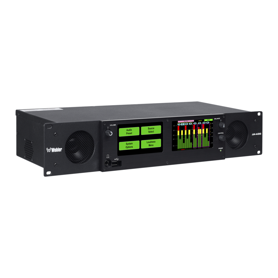
The unit also accepts Audio over IP signals via an Ethernet connector. Refer to the Specifications section or contact Wohler Sales for more information. The iAM-AUDIO is compact and simple to operate. It has touch screen LCD displays providing high resolution meters, menus and basic monitor controls. -
Page 6: Safety Symbols
7. Protect the power cord from being walked on or pinched, particularly at plug connection on the equipment and at the socket. 8. Use only the attachments/accessories specified by the manufacturer. 9. Unplug the equipment during lightning storms or when unused for long periods of time. -
Page 7: Sympathetic Vibration
Heat generated by the class D power amplifiers, power supplies, and other components is vented by slots in the sides and back of the unit. Therefore, as a safety precaution, you must allow proper ventilation on these surfaces. Sympathetic Vibration Sympathetic vibration from other equipment (cables, etc.) in the rack may be serious enough to interfere with the unit’s sound quality. -
Page 8: Ices-003
and used in accordance with the instruction manual, may cause harmful interference to radio communications. Operation of this equipment in a residential area is likely to cause harmful interference, in which case the user will be required to correct the interference at their own expense. ICES-003 This Class A digital apparatus complies with Canadian ICES-003. -
Page 9: Chapter 2: Local Operation
CHAPTER 2: Local Operation Front Panel The front panels for the 1RU and 2RU models are shown in Figures 2-1 and 2-2. Figure 2–1: iAM-AUDIO-1 (1RU) Front Panel Volume Menu / Option Display Level Meter Displays Balance Info Input - 20 - 20 - 30 - 30... -
Page 10: Rear Panel
4. Balance: This controls left/right levels for the stereo mixes. By default, it controls loudspeaker and headphone output, though other options may be set in the Web GUI preferences. 5. Adjust / Aux Volume: Reserved for future use. 6. USB 2.0 Port: This USB Type A connector allows you to use a flash drive (not supplied) to perform software updates and copy system configurations to another iAM-AUDIO or to a PC. - Page 11 Use of another power adapter provided by the user may negate the compliance or cause the monitor to not perform properly. Wohler Technologies cannot accept any responsibility for the outcome in such cases. 2. GPIO: (future implementation) This DB-9 connector provides 2 input pins and 2 output pins to perform GPIO functions as defined by the Web GUI.
- Page 12 System Setup section in Chapter 4 and to Figure 4-9 to install software licenses. 11. Analog Inputs: This DB-25 female connector accepts +10dBu broadcast level balanced audio. Tascam cables may be used, and can be purchased by contacting Wohler Sales. Refer to Figure 2-5 for the pinout of this connector. Page...
- Page 13 Figure 2-5: Analog DB25 Input Connections Pair 1 Pair 2 Pair 3 Pair 4 12. Analog Outputs: These male XLR connectors provide two balanced analog outputs: . The source of these signals Left Right is the mix of audio as monitored by the internal speakers. Figure 2-6: Analog XLR Output Connections Pin 1 Pin 2...
-
Page 14: Channel Meters And Touch Operations
Channel Meters and Touch Operations The audio mixer terminology of “solo” is used in this manual when referring to muting all but a specific audio channel or subgroup. Since the terms “group” and “subgroup” have different meanings in SDI vs. pro audio, this manual uses the term “cluster”... -
Page 15: Menu / Option Touchscreen
4. Touching the lower part of a meter cluster will mute it or un-mute it. 5. Clusters currently muted are outlined in a magenta box. 6. Mutes are additive. One or more clusters can be muted or un-muted to create custom mixes for monitoring. 7. -
Page 16: Info
Info Touching the Info button displays the iAM-Audio Info menu as shown in Figure 2-9. Figure 2-9: Info and Software Info Screens iAM-Audio Info Software Info Serial Number: 151042 MAC Address: 80:30:DC:92:FE:31 FPGA Rev: A3.5.4.3 IP Address: 172.27.2.2 Software Rev: 1.2-0 iAM-Audio Rev: 0.1.0... -
Page 17: Setup
Setup Touching the Setup button opens the iAM-Audio Setup menu as shown in Figure 2-10, which contains the Presets button. Presets are defined in the Web GUI. See Chapter 4 for further information on how to define presets. Figure 2-10: Setup Menu and Presets Menu iAM-Audio Setup Presets Touching Presets proceeds... -
Page 18: Input
Input The Input Screen displays a graphical representation of which channels from the various sources are selected for monitoring. To reach the Input Screen, touch the Input button on the Main Screen. The Input Screen is shown in Figure 2-11. Figure 2-11: Input Screen Inputs: 9 10 11 12 13 14 15 16... -
Page 19: Chapter 3: Technical Info
CHAPTER 3: Technical Info Table 3–1: iAM-AUDIO Specifications Specification Values/Domains Power Requirements 100 VAC to 240 V AC ± 10%, 50/60Hz Power Consumption 40 Watts Dimensions (1RU) 1.75” x 19” x 7.5” (44mm x 483mm x (H x W x D) 191mm), standard 19”... - Page 20 Specification Values/Domains Inputs: 8 AES channels on 4 BNC are optional AES Inputs / Outputs Output: 2 AES channels of monitored signal on 1 BNC is optional Ethernet AoIP I/O accepts either an optional Audio over IP Input / ...
- Page 21 Figure 3–1: iAM-AUDIO Block Diagram Info Input Setup Info Input S etup Page...
-
Page 22: Chapter 4: The Iam-Audio Web Gui
CHAPTER 4: The iAM-AUDIO Web GUI The self-contained iAM-AUDIO Web GUI allows you to customize the configuration of the iAM-AUDIO to suit your needs. The default presets configure the channels in each source in consecutive fashion. If the default configuration of the iAM-AUDIO suits your needs and you prefer to use it that way, then you do not need to use the iAM-AUDIO Web GUI. -
Page 23: Network Connection
Figure 4–1: Host IP Settings Close the control panel and reboot the host computer after making an IP address change to be sure the change takes effect. Either reconnect to the installed network or continue with this direct connection to access the iAM- AUDIO Web GUI. -
Page 24: Dashboard
Dashboard Throughout the Web GUI, other pages are a click or two away using the list of selections on the left side. System Overview on this Dashboard page shows all preset configurations at a glance. Figure 4–2: Dashboard Preset Overview Dashboard Selection The currently selected preset for local operation is shown full color. -
Page 25: Remote Metering
The lower part of the page shows front and rear panels for setup reference, plus alerts, status and license information. Refer to Figure 4-3. Figure 4–3: Dashboard Device Overview Remote Metering Click on the Remote Monitor page to view the audio bar graph meters for the current preset. -
Page 26: Sign In
Sign In Only authorized users should be allowed to make preset and network changes. Anybody can view the status of iAM-AUDIO units on the network, but logging in with a password is required to make any changes. When logging in is required to make a change, the page shown in Figure 4-5 will appear. -
Page 27: Channel Naming
Channel Naming Each channel will have a preassigned name in the configuration database. There is a separate set of names for each input type. Select the Input Type by clicking a check box, as shown in Figure 4-6. The default names (labels) can be changed by normal cursor text entry operations in your browser. -
Page 28: Configuration - Configure Presets
Configuration – Configure Presets Factory default Presets are provided for each input type as sixteen channels in consecutive order. Default mixes are left for odd-numbered channels and right for even-numbered channels. If one of these simple arrangements works for your application, there is no need to change any of your Presets, since the monitor can be left set to that Preset. - Page 29 switch will appear. Only one can be enabled for each Preset, though different Presets can use either one. 3. Meter numbers 01 to 16 represent the left-to-right order of monitored channels within the Preset. 4. Select a different Cluster Type (size) by clicking the box under the meter number where you want the cluster (audio group or program) to begin on the left.
-
Page 30: Configuration - Named Presets
Configuration – Named Presets Use this page to edit Preset names. Click Save to store the new name(s). Figure 4–8: Save Preset Configuration - Named Presets Selection Page... -
Page 31: System Setup
Licenses without keys will not have the box checked. Click on an unchecked box to allow entry of the license key provided by Wohler Customer Service. Once entered, saved and accepted, the new license is available for use. -
Page 32: Scan Network-Discovery
Scan Network-Discovery This page will scan the network for Wohler iAM monitors installed on the network. Other devices can have their network settings reconfigured by clicking the Edit (pencil) icon. Information about the Updates tab is in Installing Software on Networked iAM-AUDIOs. -
Page 33: Network Setup
Network Setup Make network IP Address changes for the local iAM-AUDIO unit’s Management (MGMT) Port here. Figure 4–11: Set IP Addresses Network Setup – Set IP Addresses Selection Click to Save new address and reboot iAM -AUDIO The procedure for changing the IP Address information is as follows: 1. -
Page 34: Database Management
Database Management Export Configuration Use the to back up Database Management - Database Export / Import page an iAM-AUDIO’s Preset database to a USB flash drive. Figure 4–12: Database Export Use the following steps: 1. Click the Export Presets button on the Database Management - Database Export / Import page. -
Page 35: Import Configuration
Import Configuration Use this to retrieve presets from a USB flash drive inserted in the front panel port. Follow the instructions on the bottom of the page to complete the procedure. Figure 4–13: Database Import Database Management – Import / Export Presets Selection Click to Import Presets Use the following steps:... -
Page 36: Save / Restore Database (Db)
Save / Restore Database (DB) This page is used to make a backup copy of the database within an iAM- AUDIO unit from which a Restore Database operation can be performed. The dataset stores various information about the unit, including the existing network configuration, channel names, presets, product information and other information. -
Page 37: Appendix A: Software Upgrades
Both local and network update methods require that a USB flash drive, with Wohler Update Package(s) installed on it, be inserted into the front panel USB jack. The Web GUI is required to perform the software upgrade procedure. -
Page 38: Installing The Software Locally
Installing the Software Locally Click on the System Update selection in the web browser GUI. System Information in the right pane shows currently installed software and hardware versions. Figure A–1: System Update System Update List of update file Selection packages (if any) Update System Button Use the following steps to install a new software package into the iAM-AUDIO: 1. -
Page 39: Installing Software On Networked Iam-Audios
Wohler logo, or close and reopen the browser for normal operation of the Web GUI. Installing Software on Networked iAM-AUDIOs This page will scan the network for Wohler iAM monitors installed on the network and allow firmware updates of compatible and accessible iAM- AUDIO units. - Page 40 Use the following steps: 1. Refer to the Download the Software section of this chapter for the specifics of download and file transfer to the USB flash drive. 2. Insert the USB flash drive with iAM-AUDIO update package(s) into the front panel USB jack of the networked iAM-AUDIO that you wish to update.
-
Page 41: Appendix B: Dante Network Setup
AoIP option is installed. The iAM-AUDIO is set up at the Wohler factory to be used as a slave rather than a master within the Dante network. Other devices or software, such as a Dante Controller, are expected to be responsible for most device configurations and all audio routing. -
Page 42: What Is In The Iam-Audio For Dante
What is in the iAM-AUDIO for Dante The Audinate® Brooklyn II board automatically recognizes Dante networks when installed, will alert other devices of its presence and configuration, and will configure its AoIP address per DHCP or local link protocols. There is no need to set a static address for the iAM-AUDIO Dante port, so no address entry method is provided in the iAM-AUDIO for Dante network setup. -
Page 43: Dante Device Setup
Dante Device Setup iAM-AUDIO’s default Dante Device Name is “BKLYN-II- …” followed by the last 6 digits of the Dante port MAC address, as shown in Figure B-3. This name can be changed by the Dante Controller to appear that way on the network, but that will not change the iAM-AUDIO’s unit name appearing on GUI pages and iAM-AUDIO remote metering or discovery pages. -
Page 44: Dante Clock Selection
Other changes such as Latency settings can be made by the Dante Controller through the Device View menus. Some changes may require remote rebooting of the Brooklyn II card to take effect, temporarily interrupting audio and publishing the new information to the network. Only 44.1 kHz and 48 kHz audio sample rates are currently supported by the iAM-AUDIO. -
Page 45: Aes67
page to match. AES67 The iAM-AUDIO Brooklyn II can be configured for AES67 operation. AES67 operation with Dante is limited to eight or less receive and transmit channels at 48 kHz sample rates. 24 bit linear (L24) encoding and 1 msec packet time are fixed default transmit parameters. -
Page 46: Device Lock
Figure B–7: Device View - Network Config The channels to be multicast are selected in the File menu-Create Multicast Flows window shown in Figure B-8. Figure B–8: Multicast Device Lock Audinate recently added a feature whereby a remote controller can send a command to lock Dante network devices’... -
Page 47: Dante Firmware Upgrades
Dante Firmware Upgrades Wohler iAM-AUDIO monitors ship with current Brooklyn II firmware as of the option installation date. The version information is found in the Dante Controller Device View-Status page. iAM software/firmware is tested with the latest Dante code release. Therefore it is strongly recommended that iAM-AUDIO and Dante software/ firmware be updated at the same time to ensure compatibility and support of the latest features. -
Page 48: Appendix C: Ravenna Network Setup
APPENDIX C: Ravenna Network Setup Introduction Installing the iAM-AUDIO into an existing and functioning Ravenna network is virtually plug and play. The iAM rear panel AoIP jack supports 1Gb/s and 100Mb/s Ethernet devices in Ravenna Audio over IP network configurations. iAM-AUDIO channel source selections are made by choosing Input Type ‘AoIP’... - Page 49 2) IEEE 802.1Q/SRP 3) IEEE 1722.1/AVDECC control 4) IEEE 802.1AS/gPTP 5) Compatible with Apple OS X devices, such as MacBooks and MacMini computers 6) Media clock per the AVnu specification 7) Hitless stream redundancy BACH™ Controller provides a interface to The BACH board includes a Graphical User Interface to review and manage the Bach board.
-
Page 50: Home Page
Home Page You can navigate to different pages within the Bach Controller GUI to review or perform various functions. The Home page can be accessed by entering the 172.27.2.30 IP address. It gives a device overview and stream status. Figure C–1: BACH Controller Home Page Page... -
Page 51: Patch Panel
Patch Panel The Patch page enables routing of connections between listener and talker channels for devices on the network. The highlighted green square indicates a routing connection between a source or talker (left) and a destination or listener (bottom). The Web GUI will allow selection of channels to monitor from among the listeners (bottom). -
Page 52: Controller Cloud
Controller Cloud The Cloud page shows any Ravenna devices on the given network, including any Wohler devices with the Ravenna option installed. Figure C–3: BACH Controller Cloud Page Page... -
Page 53: Source Streams
Source Streams The Source provides in-depth information on source streams that are transmitting (sourcing) Ravenna signals from devices on the network. Figure C–4: BACH Controller Source Stream Page... -
Page 54: Stream Destinations
Stream Destinations The Destination page provides in-depth information on your destination devices that are receiving Ravenna signals on the network. Clicking the Advanced button provides additional options. Figure C–5: BACH Controller Stream Destinations Page... -
Page 55: Sync
Sync The Sync page allows you to program parameters relating to Precision Time Protocol (PTP) based time synchronization of network clocks of your BACH- AES67 devices. Figure C–6: BACH Controller Sync Page Page... -
Page 56: Configuration/Device Management
Configuration/Device Management The Config page allows operations such as modifying the IP address, Packet time, Rebooting etc. Configure the Packet Time either as 1ms or 250us. Figure C–7: BACH Controller Device Management Page...
Need help?
Do you have a question about the iAM-AUDIO-1-DANTE and is the answer not in the manual?
Questions and answers