
Related Manuals for Wohler AMP2-16V-M


Summary of Contents for Wohler AMP2-16V-M
- Page 1 AMP2-16V Series • AMP2-16V-M • AMP2-E16V-M Modular Audio/Video Management and Monitoring Platform User Guide (Software Release: V7.xx) Part Number 821116, Revision M...
-
Page 2: Customer Support
Wohler Technologies. Reproduction Licensed users and authorized distributors of Wohler Technologies, Inc. products may copy this document for use with Wohler Technologies., Inc. products provided that the copyright notice above is included in all reproductions. Customer Support Wohler Technologies, Inc. -
Page 3: Table Of Contents
TABLE OF CONTENTS Contents TABLE OF CONTENTS .................. iii Contents ......................iii PREFACE ....................1 New Features ....................1 Overview ....................1 What’s New? ..................... 1 CHAPTER 1: Quick Start ................2 Introduction ....................2 Overview ....................2 Front Panel Features .................. 2 User Interface .................... - Page 4 How Do I Cluster Meters Pairs Together for Easy Readability? ......23 How Do I View the Loudness Screen? ............24 How Do I Set the Way Loudness is Calculated? ..........25 How Do I Set Up for External Surround Sound? ........... 26 How Do I Configure a Stereo Downmix for My External Surround Sound? ..
- Page 5 Introduction ....................65 Menu Navigation Overview ................65 3G SDI I/O Configuration Menu ............... 67 5.1 Downmix Parameters Screen ..............69 AES Input Configuration Menu ................. 70 AES/Analog Output Configuration Menus............71 Follow Monitor Mode Controls ..............72 Free Mix Mode Controls ................73 Arbitrary Phase Measurement Menu ..............
- Page 6 Menu Modifications................. 118 Analog I/O Card................... 119 Analog Rear Panel Adaptor ..............119 Menu Modifications................. 119 Connector Pin Outs ................119 Analog I/O and SPDIF TOSLINK Card ............. 122 Rear Panel Adaptor ................122 Menu Modifications ................. 122 Connector Pin-Outs ................122 Dolby D/E/DD+ Card ..................
- Page 7 Dante Device Setup ..................150 Dante Clock Selection ................... 151 Channel Names ................... 151 AES67 ......................152 Device Lock....................153 Troubleshooting ................... 154 Dante Firmware Upgrades ................154 APPENDIX B: Ravenna Network Setup ............155 Introduction ....................155 Ravenna Input Module Features ..............155 RAVENNA-Compatible Listener ..............
-
Page 8: Preface
PREFACE New Features Overview The preface lists the new features and functionality for this release. What’s New? There is now support for the 16-channel Dante Receiver card. Appendix A describes how to set it up within an existing Dante AoIP network. There is also support for the 16-channel Ravenna Receiver card. -
Page 9: Chapter 1: Quick Start
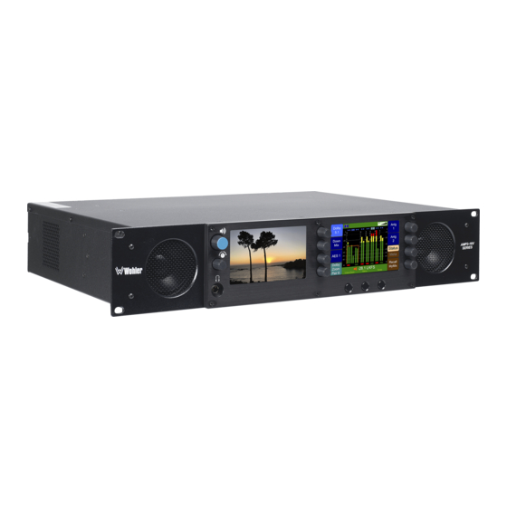
CHAPTER 1: Quick Start Introduction Overview This chapter describes how to use the front panel controls and the user interface menu system. For a more in-depth description of each menu, refer to Chapter Menu List. Front Panel Features This section describes the controls on the front panel. Figure 1–1: Front Panel Layout Volume Left Screen... -
Page 10: User Interface
metadata. 6. Right Screen: You can configure this screen to display meters, metadata, or the configuration menus and context-sensitive help. 7. Rotary Knobs: You can use the rotary knobs in two ways: by turning the knob either clockwise or counter-clockwise, or by pressing the knob like a button. -
Page 11: Help
Help If at any time you would like assistance with the function of any control, pressing the Help button starts the context-sensitive help for the screen as shown in Figure 1–3 below. Figure 1–3: Screen/Menu Help Preset Management Menu Copy Copy To Preset 1: Preset 4:... -
Page 12: Setting Up Your Monitor For The First Time
Setting Up Your Monitor for the First Time To set up your monitor quickly and efficiently, we recommend that you set up your initial configuration in the order listed below. 1. Configure the Monitor Mixer: Select the inputs to be monitored. 2. -
Page 13: Create Channel Clusters
Table 1–1: Channel List Channel Cluster Name Source (Ex: Channel (Ex: 5.1 Slot 2: 3G-SDI Channel Function (Circle One) Number Dolby) In/Pair 4) L R Lfe Ls Rs Lrs Rrs Lfh Rfh Lrh Rrh Ms N L R Lfe Ls Rs Lrs Rrs Lfh Rfh Lrh Rrh Ms N L R Lfe Ls Rs Lrs Rrs Lfh Rfh Lrh Rrh Ms N L R Lfe Ls Rs Lrs Rrs Lfh Rfh Lrh Rrh Ms N L R Lfe Ls Rs Lrs Rrs Lfh Rfh Lrh Rrh Ms N... - Page 14 Figure 1–6: Cluster Configuration Screen Cluster Configuration Screen Cluster Cluster Start Cluster Configuration Screen Select Cluster Edit Default Cluster Label Auto Set Help Save / Exit Cancel 2. Press the Auto Set control to automatically adjust the cluster arrangements to match the Channel Function settings made in the Monitor Mixer Configuration Menu.
-
Page 15: Arrange The Main Screens
7. Turn the Select Horizontal knob (or the Select Vertical knob) to select the letter to type. Press the knob to type it. 8. When you have finished typing the name, press Save/Exit to return to the Cluster Configuration Screen. 9. -
Page 16: Select The Metadata To Display On The Screen
If you select a Main Screen arrangement that includes data, proceed to the following section to specify exactly what data you want to display. 4. Select the Metadata to Display on the Screen Status Data: If you do not wish to display status data, continue on to SMPTE 2020 Metadata on the next page. - Page 17 8. Once you have defined all the status data you want to display, press Save/Exit to return to the Main Screen Configuration Menu. SMPTE 2020 Metadata: You can display either SMPTE 2020 or Dolby metadata. If you prefer to display Dolby metadata, skip to Dolby Metadata.
- Page 18 metadata is to be extracted. The possible choices include any of the 3G/HD/SD SDI cards. 5. By default, the AMP2-16V will automatically select the lowest numbered SDID containing metadata. If you would prefer to specify a different SDID, rotate the SMPTE SDID to select the desired SMPTE SDID. The ten choices include No Assoc., Pair 1 through Pair 8 and Auto Select.
- Page 19 14. Once you have defined all the status data you want to display, press Save/Exit to return to the Main Screen Configuration Menu. Dolby Metadata: Note: Only units equipped with an optional Dolby D/E/DD+ card will show this option. On the , rotate the knob to Metadata Select Menu...
-
Page 20: Save Your Setup In A Preset
are None, Dialnorm Only, Line Mode, or RF Mode. 11. Rotate the Metadata Scroll knob to scroll through the list of available Dolby metadata items. The metadata items in the list are actively refreshed by the software, and will change to reflect changes in the selected input stream. -
Page 21: Getting Support
AES. Getting Support Should you need to contact Wohler’s customer support line (see page ii for our contact information), you will save time on the phone by writing down the software and hardware versions installed in your monitor. Refer to the... -
Page 22: Chapter 2: Installation
7. Unplug the equipment during lightning storms or when unused for long periods of time. 8. Use of a cart is neither recommended nor approved by Wohler. 9. Refer all servicing to qualified service personnel. Servicing will be required under all of the following conditions: a) The equipment has been damaged in any way, such as when the power-supply cord or plug is damaged. -
Page 23: Installation Recommendations
exposed to rain or moisture, or liquid has been spilled onto the equipment. c) The equipment does not operate normally. d) The equipment has been dropped. Installation Recommendations Mounting The unit is designed to install into a standard 19" rack mounted at ear level for best high frequency response and visual observation of the monitor screen. -
Page 24: Connections And Cable Recommendations
Connections and Cable Recommendations We recommend that you limit the length of the cables that you use for feeding HD- SDI signals sources to the HD-SDI inputs of the AMPx-E8 Series units and that you use a Belden 1694A cable (or equivalent). The HD-SDI inputs (In 1 and In 2) can be up to 150 meters (492 feet) in length when used with HD signals and 75 meters (246 feet) in length when using 3G signals. -
Page 25: Rear Panel Connectors
Canada. Rear Panel Connectors Standard Connectors The AMP2-16V Series monitor back panel contains all of the connectors except for the headphone jack as shown in Figure 2–1. Note that, as you are facing the rear panel, the audio module slots are numbered from right to left. 1. -
Page 26: Basic Connections
Table 2–1: Available Add-On I/O Modules I/O Module Name I/O Module Description Two 3G/HD/SD-SDI inputs 8 de-embedded AES pairs outputs 3G/HD/SD-SDI-V Card 1 selected reclocked or re-embedded output (Includes automatic frame rate detection) AES Input Card 16 channel (eight unbalanced AES pairs) AES Output Card 16 channel (eight unbalanced AES pairs) 8 balanced channels in and 8 balanced channels... -
Page 27: Chapter 3: The "How Do I
CHAPTER 3: The “How Do I...” Chapter Introduction Overview This chapter answers many questions that naturally come up as the AMP2-16V Series monitor is first put into service. Notation In this chapter, we use a shorthand method to show you how to progress from the Main Screen to the menus. - Page 28 Figure 3–1: Screen Notation Dolby Anlg Down Anlg Main Screen Status AES 1 Meta Dolby Recall Zoom -28 LKFS MyMix Pair 6 Video/Data Menu Swap Menu Configuration Selection Menu Recall Manage Preset Presets Push knob to recall User Preset 1 Video / Input 1 SDI Input...
-
Page 29: Frequently Asked Questions
Frequently Asked Questions How Do I Select the Inputs I Want to Hear in the Speakers? This selection appears on the Monitor Mixer Configuration Menu. Main Screen Menu Configuration Selection Menu Configure Monitor Mixer Monitor Mixer Configuration Menu Figure 3–2: Monitor Mixer Configuration Menu Monitor Mixer Configuration Menu Audio Delay... -
Page 30: How Do I Cluster Meters Pairs Together For Easy Readability
How Do I Cluster Meters Pairs Together for Easy Readability? Clustering the meter pairs in logical arrangements enhances the at-a- glance readability of the meters. It also assures that the Loudness calculations are accurately represented. After setting up the meter clusters, the Cluster Select hot keys are automatically configured so that they select the clusters you defined. -
Page 31: How Do I View The Loudness Screen
How Do I View the Loudness Screen? The Loudness Screen will show detailed loudness measurements on the program source you choose, if it has 8 or fewer channels. It is quickly accessible from the Main Screen, but first you must set up a Loudness hot key. hot key is set in either the or the Loudness... -
Page 32: How Do I Set The Way Loudness Is Calculated
How Do I Set the Way Loudness is Calculated? The Loudness Screen will show detailed loudness measurements on the program source you choose. The way it calculates its readings can be set using the Loudness Measurement Menu described in Chapter 5. Access to the Loudness Measurement Menu is as follows: Main Screen Menu... -
Page 33: How Do I Set Up For External Surround Sound
How Do I Set Up for External Surround Sound? If a studio or other monitoring environment contains a surround sound system, it may be advantageous to connect the monitored sound from the AMP2-16V Series monitor to this system. Up to six pairs (12 channels) of analog or AES outputs are available for this use. - Page 34 5. Analog output cards have only 8 outputs. In order to present clusters with more than 8 channels, you must have two analog output cards installed in the system. Use the Output Group Select control to determine which analog output card carries the first 8 channels. Set the other card to carry the remaining channels.
-
Page 35: How Do I Configure A Stereo Downmix For My External Surround Sound
How Do I Configure a Stereo Downmix for My External Surround Sound? First, make sure you have set up your external surround sound system. (See the previous page.) This function is available ONLY for clusters with 8 or fewer channels. Stereo Downmix is a hot key function, so it is set up in one of the Hot Key Configuration Menus. -
Page 36: How Do I Synchronize Internal Speaker Audio With An External Video Source
How Do I Synchronize Internal Speaker Audio with an External Video Source? Audio from all input sources can be delayed before it gets to the internal speakers by up to 170 ms. This is adjustable in 1 ms increments. is enabled and adjusted in the Audio Delay Monitor Mixer Configuration . -
Page 37: How Do I Synchronize External Surround Sound Audio With Video
How Do I Synchronize External Surround Sound Audio with Video? Audio from the 3G/HD/SD-SDI inputs can be delayed so that all of its destinations, including outputs will receive the delay. The SDI input channels can be delayed up to 160 ms, adjustable in 1 ms increments. Note that if you are using both the SDI input delay and the monitor mixer delay, the effect to the internal speakers is additive for a total of up to 330 ms. -
Page 38: How Do I Monitor Dolby Bitstreams
video. Adjust so that they appear to be synchronized. 3. The Audio Delay control will then show you how much delay it needed to add. 4. If you need to set a specific delay, you may of course do that by simply adjusting the Audio Delay control to that amount. - Page 39 Figure 3–10: Hot Key Configuration Menu Hot Key 9 - 16 Configuration Menu Trim Rec 1 AES Out (4) Trim Recall Preset Key 1 Key 5 5 7 9 11 13 15 AES Mic Channe... 4 6 8 10 12 14 16 Data Status/Metadata/Preset SDI Feed from Den...
-
Page 40: How Do I Decode And Monitor A Single Dolby Bitstream
How Do I Decode and Monitor a Single Dolby Bitstream? A single Dolby bitstream from the SDI or AES inputs may be monitored continuously. The bitstream itseL doesn't have to be displayed on the Main Screen meters. You may also monitor the Dolby metadata continuously. Note: The AMP2-16V must contain the optional Dolby decoder card in order to decode a Dolby bitstream. - Page 41 which you will be monitoring the audio. This step involves configuring the monitor mixer: Main Screen Menu Configuration Selection Menu Configure Monitor Mixer Monitor Mixer Configuration Menu Figure 3–12: Monitor Mixer Configuration Menu Monitor Mixer Configuration Menu Audio Delay Clusters Delay to Speakers = 170 mS Mixer Source...
-
Page 42: How Do I Display Dolby Crc Error Counts
How do I Display Dolby CRC Error Counts? By default Dolby CRC error counts are flagged at the top of the right- hand meter screen: Figure 3–13: Main Screen Displaying Level Meters and Number of CRC Errors Dolby CRCs: 27 Dolby Anlg Anlg... -
Page 43: How Do I Display Dolby E Line Number (Guard Band)
Figure 3–14: Dolby Decoder Configuration Menu Dolby Decoder Configuration Menu Decoder Source Decode Coding Mode Slot 1 (AES All formats 1/0 (C) In) Pair 1 Bitstream Mode Pro-16 Mode Complete Main Aux Pair Channel Dialogue Level Channel 1 LtRt Downmix - 27 dBFS Frame Rate Dolby E... -
Page 44: Preset Name
Figure 3–15: Hot Key 9 - 16 Configuration Menu Hot Key 9 - 16 Configuration Menu Trim Rec 1 AES Out (4) Trim Recall Preset Key 1 Key 5 5 7 9 11 13 15 AES Mic Channe... 4 6 8 10 12 14 16 Data Status/Metadata/Preset SDI Feed from Den... -
Page 45: How Do I Use Presets To Change Inputs
How Do I Use Presets to Change Inputs? The AMP2-16V can be outfitted with far more inputs than can be monitored on a 16-channel screen. While it is possible to delve into the various menus to reconfigure which channels are monitored each time a change is needed, this would be a time-consuming task. -
Page 46: How Do I Quickly Recall Presets From The Main Screen
press Save/Exit. 3. Whenever you make menu changes and then exit to the Main Screen without saving into a preset, a yellow warning flag will appear in the header of the main screen to remind you to save the changes you make. How Do I Quickly Recall Presets from the Main Screen? While presets can always be recalled from the Recall Preset control on the Configuration Selection Menu, pressing Recall Preset hot keys on the Main... -
Page 47: How Do I Set Up A Superpair To Monitor Intercom Or Other Sources
How Do I Set Up a SuperPair to Monitor Intercom or Other Sources? A SuperPair is a 9th audio input pair that you can monitor along with the normally monitored audio channels. It can be any input pair. This special pair can be heard in the speakers or outputs, but is not metered on the Main Screen. -
Page 48: How Do I Set Up A Superpair Volume Control
How Do I Set Up a SuperPair Volume Control? A SuperPair is a 9th audio input pair that can be heard along with the normally monitored audio channels. You can reconfigure the front panel Balance control to become a SuperPair Volume control, that will work independently of the main front panel Volume control. -
Page 49: How Do I Mix Any Input(S) To Any Output(S)
How Do I Mix Any Input(s) to Any Output(s)? Any of the input channels can be mixed to any of the AES or analog outputs. The mixer controls for each AES or analog output are in the Analog or AES Output Card Configuration Menu and on the 3G SDI I/O Configuration Menu: Main Screen Configuration Selection... -
Page 50: How Do I Adjust Mixer Levels From The Main Screen
How Do I Adjust Mixer Levels from the Main Screen? Any of the input channels can be mixed to any of the AES or analog outputs. Although mix levels can be set in the output configuration menus of each output card, hot keys can be used to allow you to adjust mix levels from the Main Screen. -
Page 51: How Do I Show Mixer Output Levels On The Level Meters
How do I Show Mixer Output Levels on the Level Meters? If you have not done so already, you first need to set up a free mix in the output card. Please refer to How Do I Mix Any Input(s) to Any Output(s)? in this chapter and set up the needed output mix. -
Page 52: How Do I Configure The Audio Inputs Or Outputs
3. Now is also a good time to use the Channel Function control to designate the function of the channels in that pair. 4. Press the Set Clusters control to proceed to the Cluster Configuration Screen. On that screen, use the Select Cluster control, following by the Edit Cluster Label control to name the output meter pair. -
Page 53: How Do I Set The Clock Source
How Do I Set the Clock Source? All inputs to the AMP2-16V must be synchronized to the same clock. By default, the system will automatically select a logical clock source, such as the 3G/HD/SD-SDI card in the lowest numbered slot. However, you can also set the clock source to any AES input pair or to the Reference Genlock Input. -
Page 54: How Do I Terminate/Unterminate Aes Inputs
How Do I Terminate/Unterminate AES Inputs? AES signals should have one and only one termination. This termination should physically be at the last destination of an AES coax cable. If the AMP2-16V is the last connection in a series of AES connection, then its terminations should be turned on. -
Page 55: How Do I Lock Entry To The Menus
How Do I Lock Entry to the Menus? In some installations, it may be advantageous to lock access to the menu system. The AMP2-16V is equipped with the ability to set a simple menu access lock. Navigate to the screen: Select Menu Lock Screen Combination Main Screen Configuration Selection... -
Page 56: How Do I Find Software Version Information
5. When you leave the menu system and return to the Main Screen, the menu system is automatically locked again. How Do I Find Software Version Information? Occasionally, when speaking with a customer service representative, it is necessary to locate the software versions of the software in the AMP2-16V. This is simply a screen that can be called up. -
Page 57: Chapter 4: Features And Screens
CHAPTER 4: Features and Screens Introduction This chapter describes the screens and major features of the AMP2-16V Series monitors. Main Screen The AMP2-16V includes two high resolution LCD screens. This makes it easy to view video, metadata, and meters from a greater range of positions. The content of each screen is fully configurable. -
Page 58: Simultaneous Multi-Format Monitoring
Simultaneous Multi-Format Monitoring The AMP2-16V can monitor 16 channels of 3G/HD/SD-SDI, AES, analog, or optical inputs in any combination on the same level meter screen. It does not need to switch between different input port types to display them simultaneously on the meters, or to monitor them audibly. - Page 59 1. Video on the left screen and level meters on the right screen (Figure 4–2 below). Figure 4–2 Left: Video/Right: Meters SOLO Trim SDI-1 0 dB M/trak Dolby Pair 2 ANLG Status Pair 3 -28.1 LKFS Meta Help Menu Swap 2.
- Page 60 4. Swappable video or metadata on the left screen and level meters on the right screen (Figure 4–5 below). Figure 4–5 Left: Video or Metadata/Right: Meters SOLO Trim SDI-1 0 dB M/trak Dolby x Lev ownmix Level wpass Filter ginal Bitstream Pair 2 ANLG by Digital Sample Rate...
-
Page 61: Instant Stereo Downmix
Instant Stereo Downmix The Downmix hot key allows quick comparisons of 5.1 channel monitoring, a stereo downmix, or even a mono downmix of channels on an external surround sound system. Either LtRt or LoRo downmixes are available. Downmix parameters can be set to either fixed levels or derived from metadata. - Page 62 b) LU-S: This means that the Loudness Window is set to Short Term. c) LU-C: This means that the Loudness Window is set to Custom. The Loudness Window is set in the Loudness Measurement Menu. 2. The LU Meter scale colors have the following meaning: a) Blue: Loudness is lower than the Reference Level by the Alarm Tolerance.
-
Page 63: High Quality Audio System
5. Reset: The Reset button will reset the gathered loudness data. If it is pressed while a loudness measurement is in progress, a new reading will then immediately begin. 6. Stop: When Manual Mode is selected in the Loudness Measurement Menu, the Stop button will stop gathering loudness data. - Page 64 Figure 4–9: Audio Routing Diagram Dual 3G/HD/SD-SDI I/O Module (up to 3) Re-Embedder SDI Output & Reclocker SDI Input 1 De-Embedder SDI Input 2 Up to 3 X 8 De-embedded De-embedded SDI Audio AES Pairs from SDI AES Outputs Delay Up to 3 X 8 Pairs from up to 3 menus...
-
Page 65: Audio Processor Cards
Audio Processor Cards While the AMP2-16V comes standard with a dual input 3G/HD/SD- SDI card, it can be outfitted with up to five optional cards of various types so that it can be customized for your particular installation. 1. Dual Input 3G/HD/SD-SDI Card: This card has two selectable 3G/ HD/SD- SDI inputs, one reclocked or re-embedded 3G/HD/SD-SDI output of the selected input, and eight de-embedded AES outputs on two HD-15 connectors from the selected input. -
Page 66: Genlock Input
Genlock Input To ensure the best performance, the AMP2-16V includes a Genlock input to keep all of the inputs synchronized. Note that if the Genlock input is not used, by default the AMP2-16V will automatically locate a clock source from the input cards starting with the lowest-numbered card slot. -
Page 67: Wide Selection Of Video Formats
optical input is equipped with a sample rate converter so that its clocking may be independent from the clocking of all of the other inputs. Refer to How Do I Select the Inputs I Want to Hear in the Speakers? in Chapter 3 for details. -
Page 68: Dolby E Line Position Display
Dolby E Line Position Display As part of the Status Data Screen, the AMP2-16V will display the line position of each Dolby E bitstream contained in a 3G/HD/SD-SDI signal, relative to the guard band. This may be shown for any or all Dolby E bitstreams simultaneously on the same screen. - Page 69 A Dolby bitstream may also be decoded and output through an optional AES Output Card or an Analog I/O Card completely independently of other monitoring. Refer to How Do I Mix Any Input(s) to Any Output(s)? in Chapter 3 for details. The Dolby Zoom feature allows you to view the Dolby metadata and the level meters simultaneously while also monitoring the Dolby audio pairs in the front panel speakers.
-
Page 70: Superpair Input
a) Rotate the knob to the right (clockwise) to select soloing (blue) or to the left (counterclockwise) to select muting (red). b) Press the knob to deactivate or activate the solo or mute. c) Rotate the knob one “click” at a time to select one or the other of the channels in the pair to solo or mute. -
Page 71: Phase Monitoring
Phase Monitoring Not only can the phase relationship of any pair be monitored, but the phase between any arbitrary non-adjacent channels or pairs can also be monitored. Phase monitoring between adjacent pairs is controlled in the Monitor Mixer Configuration Menu. Arbitrary phase monitoring between any non-adjacent channels can also be set up in the Arbitrary Phase Measurement Menu. -
Page 72: Chapter 5: Menu List
CHAPTER 5: Menu List Introduction This chapter provides an in-depth description of all the menus and all their respective options and functions. Note: The menus are listed alphabetically for easy reference. Menu Navigation Overview The Menu Tree (shown in Figure 5–1) describes how to navigate from one screen to another on the AMP2-16V Series monitor so you can configure and customize the operation of the monitor to meet your needs exactly. - Page 73 Figure 5–1: Menu Tree Audio Monitoring Dolby Zoom Main Screen Main Screen Solo 1 Mute 5 Hot Key 1 Hot Key 5 Hot Key 9 Hot Key 13 Data Monitoring Solo 2 Hot Key 2 Hot Key 6 Hot Key 10 Hot Key 14 Solo 3 Dolby E Pgm 7...
-
Page 74: 3G Sdi I/O Configuration Menu
3G SDI I/O Configuration Menu This menu allows you to configure the audio from the 3G SDI I/O Card. Note that the bulk of the functionality of this menu is identical to those of the AES/Analog Output Configuration Menus, so this section will only discuss those functions that are unique to this menu. - Page 75 b) Select will let you select any input card sources, and any Dolby decoder sources (if equipped) to be re-embedded in the reclocked output. De-embedded pairs that are used as Input Mix Select sources will be delayed by the SDI Audio Delay. This may be useful when synchronizing an external video monitor with the audio signals.
-
Page 76: 5.1 Downmix Parameters Screen
touch control from the Main Screen. f) Additional 3G/HD/SD-SDI cards added to the AMP2-16V will have their own separately adjustable delay. g) The adjustable delay for the internal monitor speakers, as set in the Monitor Mixer Configuration Menu, if used, will be in addition to the SDI Audio Delay. -
Page 77: Aes Input Configuration Menu
3. Overall Offset Level: Rotating this knob selects between four possible level reductions for the center channel in the downmix: 0 dB, -3 dB, -4.5 dB, or - 6 dB. 4. Parameter Source: This control enables or disables the application of received center and surround level data, either SMPTE 2020 or Dolby, as set in the Metadata Select Menu. -
Page 78: Aes/Analog Output Configuration Menus
AES/Analog Output Configuration Menus s and controls are almost Note: Analog Output Configuration Menu identical so we are showing the Analog Output Configuration Menu in Figure 5-6 and the AES Output Configuration Menu in Figure 5-7 These menus allow you to: 1. -
Page 79: Follow Monitor Mode Controls
Follow Monitor Mode Controls In Follow Monitor mode (Figure 5–6 below) you can direct the channels selected in the Monitor Mixer Configuration Menu (Figure 5–7) to be output through the Analog (or AES) Output Card. Figure 5–6: Analog Output Configuration Menu - Follow Monitor Analog Output Slot 3 Configuration Follow Menu... -
Page 80: Free Mix Mode Controls
Free Mix Mode Controls In Free Mix mode you can mix and output any combination of channel pairs into any combination of output channels, or you can turn the output pair Off altogether. Adding a Dolby D/E Card adds the five decoded Dolby output pairs, so you can select one of many inputs (up to four other processor cards at eight channel pairs each, plus five Dolby output pairs). -
Page 81: Arbitrary Phase Measurement Menu
4. Output Assign: Rotating this knob moves a highlight between possible output channel numbers and between channels and pairs. Pressing the knob adds or removes the highlighted channel from each channel's output mix. Arbitrary Phase Measurement Menu In addition to the normal pair-wise phase indication between adjacent pairs, the left or right meter screens can also indicate the phase relationship between any two channels being displayed. -
Page 82: Audio Processor Card Menu
pair to channel pair;. Pressing this control to light the indicator enables a phase comparison between the two channels on this line. 3. Phase Compare B: Rotating this knob steps through the audible channels (except for the one you have already selected in Phase Compare A). The channel(s) selected by Phase Compare B are the Test Channels to be compared to the Reference Channels. - Page 83 Figure 5–9: Audio Processor Card Menu Audio Processor Card Menu Slot 1 Slot 5 3G SDI I/O Card No Card Installed Configuration Slot 2 Analog I/O Card Configuration Pass Dolby AES Output Card AES/SDI Slot 3 Configuration Block Dolby Outputs AES Input Card Dolby Card Configuration...
-
Page 84: Automation Menu
8. Dante Output: Pressing a knob with this description displays the Dante Output Configuration Menu. In this menu, signals can be mixed for output through the Dante network port. 9. Ravenna Output: Pressing a knob with this description displays the Ravenna Output Configuration Menu. -
Page 85: Controls
Figure 5–10: Automation Menu Automation Menu Select Select Condition Response Condition Response Slot 1 3G SDI I/O = HD P3 HD Preset Slot 1 3G SDI I/O = SD P2 SD Preset Slot 1 3G SDI I/O (Pr 1) = Dolby P4 5.1 Chan Select Auto... -
Page 86: Adding An Auto Mode Hot Key
f) Slot p AES In Pair m = Unlock g) Slot p AES In Pair m = Dolby h) Slot p AES In Pair m = No Dolby i) Default where: a) Slot n is between 1 and 3, limited by the number of SDI cards installed, b) Slot p is between 1 and 5, limited by the number of AES Input cards installed, and... -
Page 87: Cluster Configuration Screen
Cluster Configuration Screen The Cluster Configuration Screen allows you to define and select clusters for display on the Main Screen. Main Screen Menu Configuration Selection Menu Configure Monitor Mixer Monitor Mixer Configuration Menu Set Clusters Cluster Configuration Screen Figure 5–11: Cluster Configuration Screen Cluster Configuration Screen Cluster Cluster... -
Page 88: Configuration Selection Menu
control, clusters can still be revised using the Cluster Start and Cluster End controls. After the Auto Set control has been used, the clusters should be named appropriately using the Edit Cluster Label control. 4. Cluster End: Rotating this knob moves the right side of the bracket to select the ending channel of a cluster. -
Page 89: Dolby Decoder Configuration Menu
cards installed. Rotating this knob selects the video source to be displayed on the left-hand screen. 3. Configure Monitor Mixer: Pressing this knob displays the Monitor Mixer Configuration Menu where you can define the channel pairs that you will monitor and that will appear on the meters. You will also define the function of each channel. - Page 90 associated with the currently-selected bitstream (if any). For more information, refer to 4. Select the Metadata to Display on the Screen in Chapter 1 or to How Do I Monitor Dolby Bitstreams? in Chapter 3. The purpose of this menu is to set up a number of parameters related to decoding Dolby bitstreams in the AMP2-E16V.
- Page 91 When you select any one of these sources, the Dolby D/E/DD+ Card is locked to that source and cannot be used on other sources. However, you can select the Dolby Zoom Select source instead. This frees the Dolby decoder card to be used by any Dolby Zoom hot key. The system will dynamically assign it to any source that must be decoded, depending on which Dolby Zoom hot key you press.
- Page 92 Figure 5–14: CRC Error Count Dolby CRCs: 27 Dolby Anlg Anlg Down Status AES 1 Meta Dolby Φ Φ Recall Zoom -28.1 LKFS MyMix Pair 6 Video/Data Reser CRCs Swap After a few seconds, the red bar turns yellow and will remain until you reset it. Note that when a CRC error first appears, the Menu button becomes the Reset CRCs button.
- Page 93 downmix can be used, it will not produce a mono mix of the surround program because the phase-shifted channels will cancel. c) Mono Downmix: The selected surround program is downmixed to mono. d) Mute: The AUX output is muted. The AUX output of the Dolby D/E/DD+ card is available for monitoring in the Monitor Mixer Configuration Menu, along with the other four output channels.
-
Page 94: Ethernet Setup Screen
Hardware Configuration Menu Unit Info Unit Information Menu Ethernet Setup Ethernet Setup Screen Figure 5–15: Ethernet Setup Screen Ethernet Setup Screen Unit Name Unit Name: Wohler’s AMP2-16V IP Address: Select Adjust IP Mask: Gateway: Set for DNS: DHCP The IP Address cannot be 255.255.255.255... -
Page 95: Hardware Configuration Menu
Address and IP Mask. At this time, the Gateway and DNS settings are not used. Also, the center navigation button will change its text from Cancel to Save/Exit depending on whether the IP Address and IP Mask settings are usable. 4. - Page 96 automatically set to that card. If the currently-selected source is unlocked, the system will automatically choose another locked source. When this happens, the current source and the selected source fields will be different. Clock problems are displayed in red on the Main Screen as shown in Figure 5–17.
-
Page 97: Hot Key Configuration Menu 1 Through 8
6. Balance Control: When rotated or pressed, this control switches the function of the balance control knob between being a Balance control and adjusting the level of the SuperPair into the monitor mix. When this control is set to adjust the SuperPair trim, the left- right balance of the monitor mix is automatically centered. -
Page 98: Hot Key Configuration Menu 9 Through 16
1. Pressing the knob while the highlight is over the knob label displays the Label Label Menu Menu so you can rename the hot key. Refer to the in this chapter for details. Note: The label may not be changed on the Status/ Metadata or Off hot keys. The label on the Select Cluster can be changed in the Cluster Configuration Screen, but not here. -
Page 99: Label Menu
Label Menu This menu allows you to modify the knob labels for clusters, presets, and hot keys. It is accessible through the menus associated with these elements. Figure 5–19: Label Menu Label Menu Cursor Control Label Text Select Mine Annc. Existing Backspace Stm1... -
Page 100: Loudness Clusters Menu
Pressing this knob selects the letter or symbol in the character field, and places it in the next location in the Label field. Loudness Clusters Menu The Loudness Clusters Menu allows you to prevent the loudness measurement from being displayed on one or more clusters. By default, all clusters are available to be measured (even those with more than 8 channels). -
Page 101: Loudness Measurement Menu
Rotating this knob sequences through each of the clusters. Pressing this knob selects the default cluster. When set to Off, no cluster is the default. Loudness Measurement Menu The Loudness Measurement Menu sets loudness parameters and controls what loudness indications are displayed on the Main Screen and on the Loudness Screen. - Page 102 in ITU BS.1770-3 isn’t part of the standard. However, it is the value recommended by ATSC A/85, and it is chosen for the purpose of this control as a starting point and may be. It can easily be changed as required.) b) EBU R128: -23.0 LUFS 3.
-
Page 103: Main Screen Configuration Menu
4. Loudness Window: Pressing this knob will select one of the three possible settings: a) Momentary (0.4 seconds) (default): This setting will cause the loudness measurement to respond quickly to sudden jumps in audio loudness. b) Short Term (3 seconds) c) Custom (1 second to 120 minutes): If Custom is selected by pressing the Loudness Window knob, then rotating the knob will select the integration time of your choice. -
Page 104: Metadata Select Menu
2. Configure Hot Keys 1 - 8: Pressing this knob displays the Main Screen Hot Key Button Configuration Menu that will allow you to set up the function of the first eight Main Screen hot keys. Hot Key Configuration Menu 1 Through 8 in this chapter for details. - Page 105 Figure 5–23: Metadata Select Menu Metadata Select Menu Metadata Metadata Source Page 3 SMPTE 2020 Press to Configure Program Description Text Dialogue Level Color Center/Surround Mix Lev Stereo Downmix LtRt Cntr/Srnd Downmix Level LFE Lowpass Filter Font Original Bitstream Size [Empty] Dolby Digital Sample Rate RF Compression Profile...
-
Page 106: Meter Configuration Menu
Meter Configuration Menu This menu allows you to configure the appearance of the Main Screen meter characteristics, including: scale, ballistics, limits, reference levels, and upper, middle, and lower segment set points, and colors. Main Screen Menu Configuration Selection Menu Configure Main Screen Main Screen Configuration Menu... - Page 107 Table 5–1: Meter Limits and References Default Color Default Bottom Default Bounds Ballistics Scale Limit Top Limit Reference Lower Upper Float -72 dBFS 0.0 dBFS 0 dBFS = 0 dBFS -30 dBFS -20 dBFS Type I -45 dBr +3.5 dBr -20 dBFS = 0 dBr -3 dBr 0 dBr...
-
Page 108: Monitor Mixer Configuration Menu
5. Pressing the knob and then rotating it adjusts the %FS. This value cannot be adjusted to a number in excess of the calculated %FS. Rotating the knob counter-clockwise reduces the %FS in 1% increments. It may not be adjusted to less than 5%. 6. - Page 109 Figure 5–25: Monitor Mixer Configuration Menu Monitor Mixer Configuration Menu Audio Delay Clusters Delay to Speakers = 170 mS Mixer Source Dolby 5.1 Channel Pair Slot 2 SDI-3G In Slot 2 SDI-3G In Select Select Pair 4 Pair 5 Chan 1 Chan 2 Chan 3 Chan 4...
- Page 110 clicking noise. 4. Source Pair Select: Rotating this knob steps you through all the possible source pairs for this particular monitoring pair, or Off. Pressing this knob has no effect. You can choose any one of the eight channel pairs of any active input or output card, or Off.
-
Page 111: Option Configuration Menu
Option Configuration Menu This menu allows you to determine exactly how you want the audio to come through the internal speakers and whether you want to enable the Main Screen solos/mutes for this source. It also provides a link to the Hardware Configuration Menu. -
Page 112: Preset Management Menu
Parameters Screen. See 5.1 Downmix Parameters Screen in this chapter for details. 5. Configure Hardware: Pressing this knob displays the Hardware Configuration Menu. Refer to Hardware Configuration Menu in this chapter for more details. Preset Management Menu This menu allows you to name, save, copy, and clear presets. Presets should be saved after changes are made to them. -
Page 113: Select Menu Lock Combination
4. Clear Preset: Rotating this knob selects a preset to be cleared, and pressing the knob clears it. A warning appears to verify that this action was intentional. Pressing the knob a second time will clear the preset completely. 5. Copy To: Rotating this knob selects the destination preset for the copy. Pressing the knob completes the copy. - Page 114 Figure 5–28: Select Menu Lock Combination Screen - Enabled Select Menu Lock Combination Key 5 Key 1 Select Menu Lock combination by pressing the encoders to indicate the desired combination. Key 6 Key 2 To unlock the first menu, hold the center navigation button and press the combination.
-
Page 115: Smtpe 2020 Configuration Menu
4. Press the Continue control. At this point, the menu unlock combination has been forgotten, effectively unlocking the menu entry. All other system configurations and settings will remain unchanged. To again lock access to the menus after this procedure, you will need to select a new menu lock combination as described earlier in this section. -
Page 116: Status Select Menu
2. SMPTE SDID: By default, the AMP2-16V will automatically select the lowest numbered SDID containing metadata. If you would prefer to specify a different SDID, rotate the SMPTE SDID to select the desired one. The metadata list to the right of the selection indicates whether the chosen SDID contains metadata. -
Page 117: Unit Information Menu
2. Status Page 3: Rotating this knob selects among the three available pages. 3. Text Color: Rotating this knob selects the text color of your choice. Use brighter colors for data lines that need to stand out more and dimmer colors for necessary but little used data. -
Page 118: Technical Support
0.0.0.0 MAC Address: 00:03:f4:02:97:55 Serial (RS-232) Port Configuration Baud Rate: 115200 Parity: None Data Bits: Stop Bits: Handshaking: None Update Exit 1. S/W Update: Do not use this knob unless instructed to do so by Wohler technical support. Page 111... -
Page 119: Chapter 6: I/O Modules And Options
CHAPTER 6: I/O Modules and Options Introduction This chapter discusses the various Input/Output Modules and their impact on the menu system, as well as other available options for the AMP2-16V Series monitors. Distinctions Among Models Optional I/O Modules You can further customize the AMP2-16V by inserting additional I/O modules (a total of five) to the back plane. -
Page 120: Standard Models
Standard Models While a huge number of functional combinations are possible by adding I/O modules, the following typical combinations form Wohler’s standard offering. Table 6–2: Relationship Between Model Name and Included I/O Modules 3G/HD/... -
Page 121: 3G/Hd/Sd-Sdi Card
Important If a card is removed, the unit will return to the factory default settings when it is turned on again. Important Do NOT add or remove I/O Modules with system power applied. 3G/HD/SD-SDI Card 3G/HD/SD-SDI Rear Panel Adaptor After adding the 3G/HD/SD-SDI Card and its corresponding rear panel adaptor to the AMP2-16V, the rear panel adaptor provides the connectors shown in Figure 6–2. -
Page 122: Connector Pin Outs
meters and are audible through the internal speakers. Note: The AES outputs are delayed by the Audio Delay setting in the 3G SDI I/O Configuration Menu. The delay setting in the Monitor Mixer Configuration Menu has no effect on any of these outputs. -
Page 123: Aes Input Card
AES Input Card AES Input Rear Panel Adaptor After adding the AES Input Card and its corresponding rear panel adaptor to the AMP2-16V Series monitor, the rear panel adaptor provides the input connectors shown in Figure 6–3. Figure 6–3: AES Input Card Rear Panel Adaptor and Rear Card Cover Plate Menu Modifications All of the AES input pairs on the AES Input Card rear panel adaptor are selectable on the Monitor Mixer Configuration Menu and are also sources on the AES or... -
Page 124: Aes Output Card
AES Output Card AES Output Rear Panel Adaptor After adding the AES Output Card and its corresponding rear panel adaptor to the AMP2-16V, the rear panel adaptor provides the connectors shown in Figure 6–6. Figure 6–4: AES Output Card Rear Panel Adaptor and Rear Card Cover Plate Menu Modifications Pressing the AES Out knob from the Audio Processors Configuration Menu will display the AES Output Configuration Menu from which you can select and/or... -
Page 125: Avb Listener Card
AVB Listener Card AVB Listener Rear Panel Adaptor After adding the AVB Listener card and its corresponding rear panel cover to the AMP2-16V Series monitor, the AVB Ethernet connector will be exposed as shown in Figure 6–5. Figure 6–5: AVB Listener Card Rear Panel Adaptor Menu Modifications All of the AVB input pairs become selectable in the Monitor Mixer Configuration Menu and are also sources on the AES or Analog Output Cards. -
Page 126: Analog I/O Card
Analog I/O Card Analog Rear Panel Adaptor After adding the Analog I/O Card and its corresponding rear panel adaptor to the AMP2-16V, the rear panel adaptor provides the connectors shown in Figure 6–4. Figure 6–6: Analog I/O Card Rear Panel Adaptor and Rear Card Cover Plate Menu Modifications You can select the analog input from the Monitor Mixer Configuration Menu and also from the AES and Analog Output Menus. - Page 127 Table 6–4: Balanced Analog Input Connector Pin Out Function Channel 8 (+) Non-inverted Balanced Analog Input Ground Channel 8 Shield Channel 7 (-) Inverted Balanced Analog Input Channel 6 (+) Non-inverted Balanced Analog Input Ground Channel 6 Shield Channel 5 (-) Inverted Balanced Analog Input Channel 4 (+) Non-inverted Balanced Analog Input...
- Page 128 The pin out of the balanced analog output connector is listed in Table 6–5 below. Table 6–5: Balanced Analog Output Connector Pin Out Function Channel 8 (+) Non-inverted Balanced Analog Output Ground Channel 8 Shield Channel 7 (-) Inverted Balanced Analog Output Channel 6 (+) Non-inverted Balanced Analog Output Ground...
-
Page 129: Analog I/O And Spdif Toslink Card
Analog I/O and SPDIF TOSLINK Card Rear Panel Adaptor After adding the Analog I/O Card and its corresponding rear panel adaptor to the AMP2-16V, the rear panel adaptor provides the connectors shown in Figure 6–4. Figure 6–7: Analog I/O and SPDIF TOSLINK Panel Adaptor and Cover Plate Menu Modifications You can select the analog input or the Toslink Input from the Monitor Mixer Configuration Menu and also from the AES and Analog Output Menus. -
Page 130: Dolby D/E/Dd+ Card
Dolby D/E/DD+ Card Note: The Dolby D/E Card does not have a rear panel adaptor. Menu Modifications Installing a Dolby D/E/DD+ Card activates the Dolby Configuration and Metadata Display Menu. It allows the decoded Dolby signals to be monitored as set in the Monitor Mixer Configuration Menu. -
Page 131: Ravenna Aoip Receiver Card
Ravenna AoIP Receiver Card Ravenna Rear Panel Adaptor After adding the Ravenna Receiver card and its corresponding rear panel cover to the AMP2-16V Series monitor, the Ravenna AoIP Ethernet connector will appear as shown in Figure 6–9. Figure 6–9: Ravenna Receiver Card Rear Panel Adaptor Menu Modifications 16 of the Ravenna Receiver channels become selectable in the Monitor Mixer Configuration Menu and are also sources on the AES or Analog Output Cards. -
Page 132: Adding A Redundant Power Supply
Adding a Redundant Power Supply The AMP2-16V Series monitors come with a single 150W power supply that is sufficient to drive a fully-loaded monitor. However, an additional power supply (also 150W) is available as an option to provide for system redundancy. Power supply modules are to be installed into their specialized slots on the far left and far right of the back panel. -
Page 133: Adding The Dc Power Module
Adding the DC Power Module The DC power supply can be used with a redundant AC or DC power supply. To install an additional power supply, position the monitor with the rear panel facing you and follow the instructions below. 1. - Page 134 Figure 6–11: DC 4-Pin Power Connector Note: Wohler does not supply the mating connector for this option. Table 6–6: DC Power Specifications Specification Value Voltage Input Range 20VDC to 30VDC Input Current Typical <2A; Max 5A Note: The AMP2-16V monitor will not operate if the DC power is applied with reverse polarity, but doing so will not harm the unit.
-
Page 135: Adding/Removing Modules
Adding/Removing Modules Wohler’s standard models typically do not populate all five slots, allowing for the addition of other modules. This section describes the procedures for adding new cards and removing existing cards. Important After adding or removing a card from the monitor, software... -
Page 136: Adding A Dolby D/E/Dd+ Card
Adding a Dolby D/E/DD+ Card To add a Dolby D/E/DD+ Card, position the monitor with the rear panel facing you and follow the instructions below. 1. Place the monitor on a solid, static-free surface and remove the power cord(s). 2. Using a small Phillips screwdriver, remove the top cover. Figure 6–12: Remove Bottom Screw 3. - Page 137 Figure 6–14: Remove System Control Board's Rear Panel Adaptor 5. Remove the rear panel adaptor for the system control board as shown in Figure 6–14 above. 6. Gently unplug the ribbon cable from the system board. Figure 6–15: Remove System Control Board 7.
- Page 138 Figure 6–16: Dolby D/E/DD+ Option Kit 8. Remove the new Dolby D/E/DD+ Card from its shipping container being careful to remain grounded. Figure 6–16 above illustrates the card and the two standoffs (left) and the four screws (right). Figure 6-17: Attach First Standoff Standoff Screw from the Other Side 9.
- Page 139 Figure 6–18: Attach Second Standoff Standoff Screw from the Other Side 10. Attach the second standoff similarly as shown in Figure 6–18 above. Figure 6–19: Insert Dolby D/E/DD+ Card 11. Insert the Dolby D/E/DD+ Card into the slot as shown in Figure 6–17 above.
- Page 140 Figure 6–20: Tighten First Standoff Screw 12. Adjust (if needed) and tighten the first standoff screw on the opposite side of the system control board, and then attach another screw on top of the standoff as shown in Figure 6–20 above.
- Page 141 Figure 6–22: Re-Seat System Control Board 14. Firmly press the system control board back into its slot so that it is securely connected as shown in Figure 6–22. Generally, this board does not snap in. 15. Connect the ribbon cable to the system card. Figure 6–23: Replace Rear Panel 16.
-
Page 142: Removing A Dolby D/E/Dd+ Card
19. Replace the lid and the screws. Removing a Dolby D/E/DD+ Card To remove a Dolby D/E/DD+ Card, follow the instructions in reverse for Adding a Dolby D/E/DD+ Card but leave the standoffs attached to the system control board. Note: All presets will be set to a factory default appropriate for the new arrangement of cards. -
Page 143: Adding A Non-3G Card I/O Module
WARNING! Do not attempt to operate the monitor without all rear panel cover plates in place. Doing so will compromise the unit’s ability to shield contain unwanted radio emissions. Adding a Non-3G Card I/O Module To add a new 3G card, position the monitor with the rear panel facing you and follow the instructions below. -
Page 144: Removing An I/O Module
Removing an I/O Module To remove a new 3G card, position the monitor with the rear panel facing you and follow the instructions below. CAUTION! Static discharge can cause serious damage to sensitive semiconductor devices. Avoid handling the circuit boards in high static environments such as carpeted areas, and when synthetic or wool fiber clothing is worn. -
Page 145: Option Kits
Option Kits Table 6–7 below lists the option kits with their respective hardware components for your convenience. Please contact your Wohler sales representative for further information. Table 6–7: Part Numbers for Optional Hardware/Kits Part Description Number 3G/HD/SD-SDI Audio/Video I/O Card Option Kit Note: The 3G/HD/SD-SDI I/O Module does not have a separate rear panel adaptor. - Page 146 Table 6–7: Part Numbers for Optional Hardware/Kits (cont'd) Part Description Number Analog I/O and SPDIF TOSLINK Card Option 829021 (includes 256767, 919316, 919285, and 919301) 256767 Analog I/O Rear Cover for TOSLINK Child Card Analog I/O Rear Panel Adaptor for TOSLINK Child 919316 Card Analog I/O Module with TOSLINK Child Card...
-
Page 147: Chapter 7: Specifications
CHAPTER 7: Specifications Introduction This chapter lists the specifications for the AMP2-16V Series monitors. Compliance All components comply with UL, CE, FCC, and RoHs specifications. Standards Loudness measurements may be set up to comply with either ITU- 1770-3 or EBU R128 standards. - Page 148 Selectable: • • • Ext. VU • Level Meter Scales • • Nordic • • Custom Selectable: • Meter range • Meter thresholds • Reference Level Meter Characteristics • Segment Colors • Ballistics • Phase (pair-wise or arbitrary) Peak Acoustic Output 104 dB SPL (@ 2 feet) Power Output 15W (30W peak) per channel...
-
Page 149: Chapter 8: Troubleshooting
This chapter lists the potential error and warning messages in the event the AMP2- 16V Series monitor may experience an unexpected condition. If on the outside chance you cannot recover from an error message, contact Wohler’s customer support. Wohler’s contact information is on the copyright page of this document. Normal Messages Occasionally, if you may make changes to your system, you may receive an unexpected message the next time you power up the AMP2-16V Series monitor. -
Page 150: Restart
Figure 8–2: Removed Module Message Did you add or remove an optional module? The system module list has changed. This is normal if you recently added or removed a module. Press Initialize to set all presets to defaults and to update the module list, or press Serial Port to enable serial port and Ethernet access. -
Page 151: Error Messages
Press Reboot to clear this issue. If this issue recurs after several restarts, connect a PC to the serial port and run a terminal emulation program. Then restart once more. Contact Wohler Technical Support if this problem persists. Reboot Continue... -
Page 152: Serial Port Access
Serial Port Access In the event of the following error, please print the report and have it available before contacting Wohler’s customer support. Figure 8–6: Serial Port Access Message Serial Port Access The system has encountered an operation error. Cycle the power on the monitor and connect your laptop/PC to the serial port to view a report. -
Page 153: Appendix A: Dante Network Setup
APPENDIX A: Dante Network Setup Introduction Installing the AMP2-16V into an existing and known functional Dante network is virtually plug and play. The Dante module rear panel AoIP jack supports 1Gbs and 100Mbs Ethernet devices in Dante Audio over IP network configurations. It can receive 16 channels of audio from any available sources. -
Page 154: Brooklyn Ii™ Controller Interface
3) IGMP v3 support 4) Session Announcement Protocol (SAP) support Brooklyn II™ Controller Interface The Brooklyn II board includes a Graphical User Interface to review and manage the network. It provides an interface to: 1) Manage connections with ease a) Display discovered devices and streams b) Connect streams from network to local destinations c) Start, stop and monitor stream health/status 2) Enable local Brooklyn II™... -
Page 155: Routing To The Amp2-16V
Routing to the AMP2-16V The AMP2-16V is set up by Wohler to be used as a slave rather than a master within the Dante network. Other devices, or software such as Dante Controller, are expected to be responsible for most device configurations and all audio routing. -
Page 156: What Is In The Amp2-16V For Dante
What is in the AMP2-16V for Dante The Audinate Brooklyn II board automatically recognizes Dante networks when installed, will alert other devices of its presence and configuration, and will configure its AoIP address per DHCP or local link protocols. DHCP works best and is recommended. -
Page 157: Dante Device Setup
Dante Device Setup The AMP2-16V’s default Dante Device Name is “BKLYN-II- …” followed by the last 6 digits of the Dante port MAC address. This name can be changed by the Dante Controller to appear that way on the network. Figure A-4: Dante Device Name Dante Device Name Figure A-5: Device Name Change... -
Page 158: Dante Clock Selection
Important: Only 48kHz audio sample rates are currently supported by the AMP2-16V. Default rate is 48kHz, which can only be changed via network reconfiguration such as Dante Controller. Connected devices must be set to the same rate. Dante Clock Selection While the Brooklyn’s internal clock is highly accurate, the AMP2-16V does not have provisions for external audio sync clocks or GPS time sources. -
Page 159: Aes67
AES67 The AMP2-16V Brooklyn II can be configured to support multicast AES67 operation. Session Announcement Protocol (SAP) should be used. AES67 operation with Dante is limited to eight or less receive channels at a 48 kHz sample rate. 16 bit (L16) or 24 bit (L24) encoding and 125/250/333/100 usec packet times can be received. -
Page 160: Device Lock
Figure A-8: IP Address Settings The channels to be multicast are selected in the Dante Controller File menu-Create Multicast Flows window. Figure A-9: Multicast Channel Selection Device Lock There a feature whereby a remote controller can send a command to lock Dante network device configurations. -
Page 161: Troubleshooting
Dante Firmware Upgrades Wohler AMP2-16V monitors ship with current Brooklyn II firmware as of the final test date. The version information is found in the Dante Controller Device View- Status page. AMP2-16V software/firmware is tested with the latest Dante code release. -
Page 162: Appendix B: Ravenna Network Setup
APPENDIX B: Ravenna Network Setup Introduction Installing the AMP2-16V into an existing and functioning Ravenna network is virtually plug and play. The AMP2-16V Ravenna input module supports 1Gb/s and 100Mb/s Ethernet devices in Ravenna Audio over IP network configurations. AMP2- 16V channel source selections are made by choosing Source Pair Select ‘Ravenna’... -
Page 163: Avb Ethernet Features
e) 48 kHz and 96 kHz audio sampling rates f) 1 to 8 audio channels per stream g) Up to 2 streams 6) Media clock support a) 48 kHz and 96 kHz 7) IGMP v3 support 8) Session Announcement Protocol (SAP) support AVB Ethernet Features AVB uses the concept of streams and channels. -
Page 164: Home Page
Home Page You can navigate to different pages within the Bach Controller GUI to review or perform various functions. The Home page can be accessed by entering the 172.27.2.30 IP address. It gives a device overview and stream status. Note: The IP address given above is only the factory default setting, but you can change it if necessary. - Page 165 It should have its own 1Gbps router. However, at least one computer must be connected to the Ravenna network to perform configuration. Set the Ethernet IP address of the Ravenna option into the "eth1" line on the Device Configuration page. The address must be on the same subnet as the other devices on the Ravenna network.
-
Page 166: Controller Cloud
Controller Cloud The Cloud page shows any Ravenna devices on the given network, including any Wohler devices with the Ravenna option installed. After the configuration described in the previous section, the devices you have set up should now appear on the Controller Cloud page. -
Page 167: Sync
Sync The Sync page allows you to program parameters relating to Precision Time Protocol (PTP) based time synchronization of network clocks of your BACH AES67 devices. For each of the devices you set up, you may check its associated Sync page. -
Page 168: Source Streams
Source Streams The Source provides in-depth information on source streams that are transmitting (sourcing) Ravenna signals from devices on the network. Check the Source tab of the source card web page. At lease one source much be turned on. Figure B-6 shows a Source page with six sources turned on. The status of each source should be green. -
Page 169: Stream Destinations
Stream Destinations The Destination page provides in-depth information on your destination devices that are receiving Ravenna signals on the network. Clicking the Advanced button provides additional options. Note: The Destinations must be set to ON. An AMP2-16V should have (at most) two destinations - TDM.0 and TDM.1. Figure B–7: BACH Controller Stream Destinations In the event that the Patch tab will not allow you to route to TDM.0 or TDM.1, use this tab to delete all sources routed to those destinations by clicking on the trash... - Page 170 Figure B–8: Deleting Stream Destinations Page 163...
-
Page 171: Patch Panel
Patch Panel The Patch page enables routing of connections between listener and talker channels for devices on the network. The highlighted green square indicates a routing connection between a source or talker (left) and a destination or listener (bottom). The Web GUI will allow selection of channels to monitor from among the listeners (bottom). -
Page 172: Troubleshooting
This can be the result of a variety of causes. Refer to Table B-1 for solutions to the problem. If after following the advice in the table, you still cannot resolve the issue please contact Wohler Technical Services for additional help. Contact information is on the second page of this manual.
Need help?
Do you have a question about the AMP2-16V-M and is the answer not in the manual?
Questions and answers