Table of Contents
Advertisement
Quick Links
Advertisement
Table of Contents

Related Manuals for Wohler AMP1-16-M


Summary of Contents for Wohler AMP1-16-M
- Page 1 AMP1-16-M 1RU, 16-Channel, 3G/HD/SD-SDI Audio Monitor User Guide (Software Release: 4.0x) Part Number 821189, Revision L 8 2 1 1 8 9 : A M P1 -1 6 -M U s e r G u i d e © 2 0 1 4 Wo h l e r Te c h no lo g i e s , I n c . A l l r i g h t s r e s e r ved .
- Page 2 In no event will Wohler Technologies, Inc. be liable for direct, indirect, special, incidental, or consequential damages resulting from any defect in the hardware, software, or its documentation, even if advised of the possibility of such damages.
-
Page 3: Table Of Contents
Trim Screen ..............12 USB Port Functionality ........... 14 Copying a Configuration From the AMP1-16-M ..... 15 Copying a Configuration File from the AMP1-16-M ..15 Update Menu ............16 8 2 1 1 8 9 : A M P1 -1 6 -M U s e r G u i d e... - Page 4 Chapter 3. AMP1-16-M Graphical User Interface (GUI) Manager ......17 Introduction..............17 Overview ..............17 Topics ..............17...
- Page 5 Technical Functional Overview ......... 45 Appendix A. Connecting the AMP1-16-M to a LAN ....47 Introduction ..............47 Overview..............47 Topics ..............47 Requirements ...............
- Page 6 8 2 1 1 8 9 : A M P1 -1 6 -M U s e r G u i d e © 2 0 1 4 Wo h l e r Te c h n o l o g i e s , In c . A l l r i g h t s r e s e r ve d .
-
Page 7: Quick Start
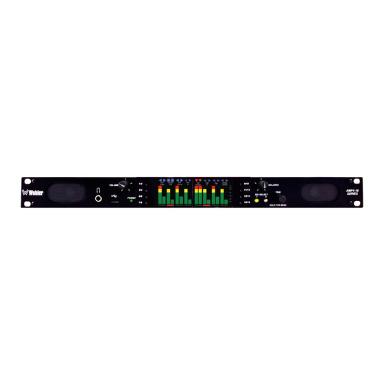
Quick Start Introduction Overview The AMP1-16-M is a 1RU, 16-channel, 3G/HD/SD-SDI audio monitor. This unit comes with two 2.4” graphics screens that work together to display 16 channels of audio level metering. You can both visibly and audibly monitor any de-embedded channel pair or pairs of the selected 3G/HD/SD-SDI input signal. -
Page 8: Safety
Ch a p te r 1 Q ui ck S ta r t Sa f et y Safety Instructions Read, keep, and follow all of these instructions; heed all warnings. Do not use this equipment near water. Use only a dry cloth to clean the equipment. Do not block any ventilation openings. -
Page 9: Safety Symbols
C ha p te r 1 Quick Start Sa fe ty Safety Symbols WARNING: The symbol to the left warns of electric shock hazard inside the unit. Disconnect the power cord before removing access panels when installing upgrades. Only qualified service personnel are to operate the equipment with covers removed, and are to exercise caution to avoid personal injury. -
Page 10: Mechanical Bracing
Ch a p te r 1 Q ui ck S ta r t Co m p l i a nc e materials between adjacent vibrating surfaces, or tying up loose cables, etc., may be required to stop vibrations external to the unit. Mechanical Bracing The 1RU chassis is securely attached to the front panel. -
Page 11: Ic-Eces-003
USB 2.0 Port: This USB Type A connector allows you to use a flash drive (not supplied) to copy system configurations to another AMP1-16-M or to a PC and allows you to update the unit’s firmware (Version 4 and later). - Page 12 The LED is also a solid yellow when it is booting. Yellow The LED blinks yellow when a firmware update is in progress. The AMP1-16-M is not receiving AC power. • Metering: These screens work together to display bar graphs and the configuration menus.
-
Page 13: Rear Panel
Analog Audio Outputs (Inputs and Outputs) (Left & Right) • Power: The AMP1-16-M uses a standard IEC power cord for the 100 to 240 VAC ±10%, 50/60 Hz power connection. • 3G/HD/SD-SDI Inputs: These two BNC connectors accept the 3G/HD/SD-SDI input signals. - Page 14 Ch a p te r 1 Q ui ck S ta r t Re a r P a ne l 8 2 1 1 8 9 : A M P1 -1 6 -M U s e r G u i d e ©...
-
Page 15: Operation
C ha p te r 2 Operation I n tr od uc ti on CHAPTER 2 Operation Introduction Overview This chapter describes how to operate the AMP1-16-M. Topics Topics Page Main Screen Trim Screen USB Port Functionality 8 2 1 1 8 9 : A M P1 -1 6 -M U s e r G u i d e ©... -
Page 16: Main Screen
O pe ra t i on M a i n S cr ee n Main Screen After powering up the AMP1-16-M and connecting an SDI input, you should see the Main Screen , which will be similar to the one shown in Figure 2–1... - Page 17 Volume Balance The channel pairs can be given unique names. To do this, simply connect a PC to the Ethernet port and run the AMP1-16-M GUI setup program. Refer to Appendix A on page 8 2 1 1 8 9 : A M P1 -1 6 -M U s e r G u i d e ©...
-
Page 18: Trim Screen
Trim more. In the menus, whether internal or in the AMP1-16-M PC setup program, you can set many other operating characteristics of the AMP1-16-M to your exact needs. Refer to Chapter 3 on page •... - Page 19 C ha p te r 2 Operation T ri m Scr e en You can adjust a channel pair by pressing one of the eight Channel Select buttons to highlight the icons at the top of the meters and then turning the Trim knob to increase or decrease the gain.
-
Page 20: Usb Port Functionality
USB flash drive which can then be inserted into the unit. Appendix D on page Immediately after connecting the flash drive to your AMP1-16-M, the Flash Drive Connected screen displays (interrupting any current functions except an Ethernet connection) as shown in Figure 2-5: below. -
Page 21: Copying A Configuration From The Amp1-16-M
File Remove the flash drive from the USB port. Copying a Configuration File from the AMP1-16-M To copy a file to the flash drive from the AMP1-16-M, press Save from the screen. The Flash Drive Connected Save to Flash... -
Page 22: Update Menu
Refer to Appendix C: Performing the Software Upgrade on page 59 for upgrading the AMP1-16-M software. 8 2 1 1 8 9 : A M P1 -1 6 -M U s e r G u i d e... -
Page 23: Chapter 3. Amp1-16-M Graphical User Interface (Gui) Manager
AMP1-16-M. I m po r ta nt: If you have not yet installed the AMP1-16-M Manager setup software into your PC and connected it to the AMP1-16-M, you must complete all the steps in Appendix A on page 47 before continuing. -
Page 24: Running The Amp1-16-M Manager
Ru n ni n g th e A M P1 -16 -M M a na g er Running the AMP1-16-M Manager The AMP1-16-M Manager allows you to customize the monitor’s configuration to perfectly suit your needs. When a unit is selected in the Manager's Units Responding... -
Page 25: The Options Tab
C ha p te r 3 AMP1-16-M Graphical User Interface (GUI) Manager T he O pt i on s T a b comprised of the top and bottom field, and each field allows up to seven characters. : For each channel pair, click Channel Pair Phase Indicators the button to toggle the phase indication on or off. - Page 26 Audio Muting and Delay Non-Audio PA Header Note: The AMP1-16-M detects PA headers that represent encoded data streams. 8 2 1 1 8 9 : A M P1 -1 6 -M U s e r G u i d e...
- Page 27 1 minute increments from 5 minutes to 119 minutes, and in 1 hour increments from 2 hours to 24 hours. The default setting is 8 hours. If the AMP1-16-M is in operation for the screen saver time-out period and no front panel controls have been turned or pressed, the screens will dim by a certain amount.
-
Page 28: The Ethernet Tab
Ethernet tab. Figure 3–3 AMP1-16-M Manager Ethernet Screen 8 2 1 1 8 9 : A M P1 -1 6 -M U s e r G u i d e © 2 0 1 4 Wo h l e r Te c h n o l o g i e s , In c . A l l r i g h t s r e s e r ve d . - Page 29 Appendix C on page 59 • Programming Files—Check for Updates : Clicking this button checks the Wohler FTP site for updated software. Note: If Update All is checked, all the files on the local computer will be updated, regardless of whether or not they are current.
-
Page 30: The Usb Tab
You can copy up to seven configuration files to or from a USB flash drive connected to your computer. You can then use this USB flash drive to copy those settings into an AMP1-16-M using the front-panel USB connector. Note:... - Page 31 C ha p te r 3 AMP1-16-M Graphical User Interface (GUI) Manager T h e U S B T a b Figure 3–4 AMP1-16-M Manager USB Screen • This pane displays a list that shows the seven Flash Drive Files: possible files in the folder of the flash drive.
- Page 32 • Create Update on Flash Drive: Whether a new update was available on the Wohler website or not, this button can be used to create a software update on the attached USB flash drive. After this operation is performed, AMP1-16-M units will recognize that an update is available on the flash drive and will offer to update themselves from it.
-
Page 33: Chapter 4. Internal Menu System
I m po r ta nt : The AMP1-16-M local menus cannot be used at the same time that the PC setup software is connected. If this happens, the PC Setup Software will take precedence and display a yellow diamond notifying you about the PC connection. -
Page 34: Menu Navigation Overview
Ch a p te r 4 I n te r na l M e nu Sy s te m M e nu N a vi ga t i on O v er vi e w Menu Navigation Overview You can launch the menu system by pressing and holding the Trim button for three seconds. -
Page 35: Audio Menu
C h a pte r 4 Internal Menu System A u d io M e nu • : Pressing this button closes this menu and opens the previous Back menu, one step up the menu tree. • : Pressing this button closes this menu and opens the next Next menu, one step down the menu tree. -
Page 36: Trim Menu
Ch a p te r 4 I n te r na l M e nu Sy s te m T r im M e nu • : Pressing this button fixes the line level of the analog outputs Fixed as they are in the SDI signal, where -20 dBFS = +4 dBu (± 1 dB). This is the default setting. -
Page 37: Channel Assignment Menu
C h a pte r 4 Internal Menu System C h a nn el A s s ig n m e nt M en u Pressing this button puts the product in mode Trim Mode: Trim and automatically selects Enabled for the Enabled/Disabled button. -
Page 38: Options Menu
119 minutes (in 1-minute increments) and from 2 hours to 24 hours (in 1-hour increments). The default setting is 8 hours. If the AMP1-16-M is in operation for the screen saver timeout period and no front panel controls have been turned or pressed, the screens will dim by a certain amount. - Page 39 • : 4 ms Delay The AMP1-16-M can detect whether a digital audio stream contains PCM encoding, or some other compressed data format such as Dolby Digital™ , in two different ways. The bitstream contains a non-audio bit. When set, this indicates that the bitstream is not PCM encoded, and therefore, should be muted.
-
Page 40: Meter Type And Reference Menu
Ch a p te r 4 I n te r na l M e nu Sy s te m M e te r T y pe a n d Re fe r en ce M e nu turn the selected phase indicator . - Page 41 C h a pte r 4 Internal Menu System M e te r T y pe a nd Re fe r en ce M e nu Table 4–1 Meter Limits and References (Continued) Default Color Default Ballistics Bottom Default Bounds Scale Top Limit Limit...
- Page 42 Ch a p te r 4 I n te r na l M e nu Sy s te m M e te r T y pe a n d Re fe r en ce M e nu o First press selects both channels for listening. o Second press leaves only channel 3 selected.
-
Page 43: Meter Segment Menu
C h a pte r 4 Internal Menu System M e te r S eg m e n t M e nu Meter Segment Menu On the , you can customize your level meter Meter Segment Menu segments thresholds and colors. Figure 4–7 Meter Segment Menu Meter Segment Menu... -
Page 44: Version And Ethernet Menu
Trim for 3 seconds • : Pressing this button opens a cautionary window Factory Default to verify that you really want to restore the AMP1-16-M setup to the factory default. If you press the button again, the Factory Default action proceeds and the unit will restart. - Page 45 C h a pte r 4 Internal Menu System V e rs i on a nd E th e rn e t M e nu I m po r ta nt: If the IP information has been changed, the unit will have to restart. A warning diamond will display, and you will need to confirm or cancel before proceeding.
- Page 46 Ch a p te r 4 I n te r na l M e nu Sy s te m V er s i on a nd E th er n et M e nu 8 2 1 1 8 9 : A M P1 -1 6 -M U s e r G u i d e ©...
-
Page 47: Chapter 5. Features And Specifications
C ha p te r 5 Features and Specifications I n tr od uc ti on CHAPTER 5 Features and Specifications Introduction Overview This chapter lists the features and specifications of the features and options of each local, internal menu. Topics Topics Page... -
Page 48: Features
Ch a p te r 5 F e a tur e s a n d S pe ci f ic a ti on s Fe a tu r es Features • Totally digital system architecture with high fidelity Class D amp •... -
Page 49: Compliance
C ha p te r 5 Features and Specifications Co m p l ia n ce Compliance All components comply with UL, CE, and RoHs specifications. The AMP1-16-M also meets FCC Part 15 compliance. Specifications Table 5–1 Specifications Specification Values/Domains Power requirements 100 V to 240 V AC ±... -
Page 50: Audio Formats
<0.05% at any level below limit Electrical Distortion threshold Audio Formats All of the audio formats listed in Table 5–2 below are available for monitoring in the AMP1-16-M. Table 5–2 Audio Formats Standard Format Rate 29.97 8 2 1 1 8 9 : A M P1 -1 6 -M U s e r G u i d e ©... -
Page 51: Technical Functional Overview
59.94 Technical Functional Overview Figure 5–1 on page 46 illustrates the overall functionality of the AMP1-16-M monitor. Note: Stereo phase indication measurement occurs in the signal chain before it is routed to the speakers. 8 2 1 1 8 9 : A M P1 -1 6 -M U s e r G u i d e ©... - Page 52 T e chn i ca l Fu n cti o na l O ve r vi e w Figure 5–1 AMP1-16-M Block Diagram 8 2 1 1 8 9 : A M P1 -1 6 -M U s e r G u i d e...
-
Page 53: Appendix A. Connecting The Amp1-16-M To A Lan
AMP1-16-M to a LAN Introduction Overview This chapter describes how to connect your PC to your AMP1-16-M through a local area network (LAN) and to configure the monitor using the graphical user interface (GUI) on a PC. Alternatively, you may connect your unit to your computer directly with a single Ethernet cable. -
Page 54: Requirements
Launch the web browser and navigate to the Wohler web site: www.wohler.com. Decision Point: If you already have a member user ID and password for the Wohler web site, then log in by clicking on the Member Sign In link at the top right hand corner of the home page and sign in. -
Page 55: Installing The Amp1-16-M Manager
Connecting the AMP1-16-M to a LAN I ns ta l l i ng th e A M P 1- 16 -M M a n a g er Once you have successfully logged into the Wohler web site, click Products from the home page menu bar and go through the sub-... -
Page 56: Launching The Amp1-16-M Manager
AMP1-16-M Manager AMP1-16-M Manager appears, it will display the SDI 1 Setup tab by default. Figure A–1 AMP1-16-M Manager SDI 1 Setup Tab Click the Ethernet tab. Figure A–2 AMP1-16-M Manager Ethernet Tab 8 2 1 1 8 9 : A M P1 -1 6 -M U s e r G u i d e ©... -
Page 57: Adding Your Amp1-16-M To Your Network
Note: The unit name may only be assigned using an Ethernet connection. If you have not already done so, connect an Ethernet cable from the Ethernet port of the AMP1-16-M (labeled Ethernet ) to the network. Click... - Page 58 Enter the Unit IP Mask (Optional) Enter a Unit Name of up to 15 characters. The name you select for this AMP1-16-M should denote its position or function within your facility so that it can be easily recognized later Click Update to close the dialog.
- Page 59 Button is grayed, it means the IP Find Find information is not correct. Important: You must see your AMP1-16-M listed in the Units Responding area. If not, double-check your connections. If the monitor still does not display, call Wohler’s technical assistance. (See Wohler’s contact into on page ii.)
- Page 60 A pp en d ix A C on n ec ti ng th e A M P 1- 16 -M to a LA N A dd i ng Yo u r A M P 1- 16 -M to Y ou r N e tw o rk 8 2 1 1 8 9 : A M P1 -1 6 -M U s e r G u i d e ©...
-
Page 61: Appendix B. Using A Direct Connection
I m po r ta nt: If you have not yet installed the AMP1-16-M Manager setup software into your PC you must do that first. Please see the download and installation instructions in Appendix A before continuing. -
Page 62: Using A Direct Connection
Ethernet), disable the ports you will not be using (especially wireless port(s)). Restart your computer. Start the AMP1-16-M Manager. Your unit should eventually appear in the Units Responding window of the Manager GUI. Depending upon your computer, it may take a few minutes for the DHCP negotiations to take place. - Page 63 Disconnect the computer from the unit. Of course, if you are familiar with setting compatible static IP addresses and subnets in both your host computer and the AMP1-16-M, that option is open to you as well. You may use either an Ethernet patch cable or a crossover cable for the connection.
- Page 64 A pp en d ix B U s in g a D i re ct C o nn ec ti on U si n g a D ir e ct C on n ec ti on 8 2 1 1 8 9 : A M P1 -1 6 -M U s e r G u i d e ©...
-
Page 65: Appendix C. Upgrading The Amp1-16M Using Ethernet
AMP1-16-M. I m po r ta nt: If you have not yet installed the AMP1-16-M Manager setup software into your PC you must do that first. Please see the download and installation instructions in Appendix A before continuing. -
Page 66: Checking For Updates
U pg r a di n g th e A M P1 -16 M u si n g E the r ne t Ch e ck i n g f or U pd a te s Checking for Updates Before establishing the connection to the AMP1-16-M, you should check to see if any software updates are currently available. Launch the from your PC’s desktop. - Page 67 C h ec k i ng fo r U p da t es Figure C–2 No New Files Dialog In the event the system discovers updates to the AMP1-16-M firmware stored on your hard drive, the system will display the dialog shown in Figure C-3 below.
-
Page 68: Upgrading The Amp1-16-M
Please continue on to Upgrading the AMP1-16-M instructions below. Upgrading the AMP1-16-M Figure C–5 AMP1-16-M Manager SDI Ethernet Screen To update the AMP1-16-M of your choice, click the one you want to update from the area. Units Responding Click Update... -
Page 69: Appendix D. Upgrading The Amp1-16-M Using A Usb Flash Drive
A p pe n di x D Upgrading the AMP1-16-M Using a USB Flash Drive I n tr od uc ti on APPENDIX D Upgrading the AMP1-16-M Using a USB Flash Drive Introduction Overview This chapter describes how to download software upgrades to your PC using a USB Flash Drive. -
Page 70: Upgrading The Software Using A Usb Flash Drive
A pp en d ix D U pg ra d i ng th e A M P 1- 16 -M U s i ng a U SB Fl a s h D ri v e U pg r a di n g th e S of tw a r e U s i ng a U S B Fl a s h Dr i ve Upgrading the Software Using a USB Flash Drive 1. - Page 71 A p pe n di x D Upgrading the AMP1-16-M Using a USB Flash Drive U pg ra d i ng th e S of tw a r e U s i ng a U S B F l a sh Dr i ve...
- Page 72 Unconditionally the flash drive into the AMP1-16-M, even if it the same version already is installed and even if the flash drive version is a lower version than what is already installed. The next screen to appear will describe what to expect in the installation process.
- Page 73 A p pe n di x D Upgrading the AMP1-16-M Using a USB Flash Drive U pg ra d i ng th e S of tw a r e U s i ng a U S B F l a sh Dr i ve Figure D–6...
- Page 74 A pp en d ix D U pg ra d i ng th e A M P 1- 16 -M U s i ng a U SB Fl a s h D ri v e U pg r a di n g th e S of tw a r e U s i ng a U S B Fl a s h Dr i ve 8 2 1 1 8 9 : A M P1 -1 6 -M U s e r G u i d e ©...
Need help?
Do you have a question about the AMP1-16-M and is the answer not in the manual?
Questions and answers