
Related Manuals for Texas Instruments RM46


Summary of Contents for Texas Instruments RM46
- Page 1 RM46 Hercules Development Kit (HDK) User's Guide Literature Number: SPNU566A September 2012 – Revised September 2013...
-
Page 2: Table Of Contents
Contents ............................Preface ........................Introduction ......................Scope of Document ..............RM46 HERCULES Development Kit (HDK) Features ....................HDK Board Block Diagram ....................... RM46 HDK Contents ......................HDK Specifications ......................Basic Operation ......................... Memory Map ........................ Power Supply ......................Physical Description ........................ - Page 3 List of Figures ..................1-1. RM46 HDK Board Block Diagram .................. 2-1. RM46 HDK Board, Interfaces Top Side ....................2-2. Connectors on RM46 HDK ..................... 2-3. CAN Bus Termination ................2-4. J2, J3 CAN Bus Interface (Screw Terminal) ...................
-
Page 4: Preface
This document describes the board level operations of the RM46 Hercules™ Development Kit (HDK). The HDK is based on the Texas Instruments RM46L852 Microcontroller. The RM46 HDK is a table top card that allows engineers and software developers to evaluate certain characteristics of the RM46L852 microcontroller to determine if the microcontroller meets the designer’s application requirements as well as... -
Page 5: Introduction
Introduction This development kit provides a product-ready hardware and software platform for evaluating the functionality of the Texas Instruments RM46 microcontroller family. Schematics, list of materials, and PCB layout are available to ease hardware development and reduce time to market. -
Page 6: Hdk Board Block Diagram
– Type A to mini B USB cable for using on board XDS100V2 JTAG emulator – Ethernet cable – Flashlight for light sensor demo • CCS DVD Containing: – Texas Instruments’ Code Composer Studio™ Integrated Development Environments (IDE) • Hercules DVD Containing: – Hercules Safety Demos – Hardware Abstraction Layer Code Generator (HALCoGen) –... -
Page 7: Hdk Specifications
(P1), a 2.5 mm, barrel-type plug. Internally, the +12 V input is converted into +1.2 V, +3.3 V and +5.0 V using Texas Instruments swift voltage regulators and PTH power module. The +1.2 V supply is used for the MCU core while the +3.3 V supply is used for the MCU's I/O buffers and other module on the board. -
Page 8: Physical Description
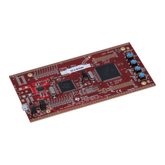
This section describes the physical layout of the RM46 HDK board and its interfaces. Board Layout The RM46 HDK board is a 4.9 x 4.3 inch (125 x 109 mm) eight layer printed circuit board that is powered by an external +5 V to approximately +12 V only power supply. -
Page 9: Connectors
Connectors The HDK board has 16 interfaces to various peripherals. These interfaces are described in the following sections. RM46L852 Figure 2-2. Connectors on RM46 HDK SPNU566A – September 2012 – Revised September 2013 Physical Description Submit Documentation Feedback Copyright © 2012–2013, Texas Instruments Incorporated... -
Page 10: 20-Pin Arm Jtag Header
The J1 connector is used to provide a 10/100 Mbps Ethernet interface. This is a standard RJ-45 connector. The cable end pinout for the J1 connector is shown in Table 2-3. Physical Description SPNU566A – September 2012 – Revised September 2013 Submit Documentation Feedback Copyright © 2012–2013, Texas Instruments Incorporated... -
Page 11: Can Interface
The two resistors should match as close as possible. Figure 2-3. CAN Bus Termination Figure 2-4. J2, J3 CAN Bus Interface (Screw Terminal) SPNU566A – September 2012 – Revised September 2013 Physical Description Submit Documentation Feedback Copyright © 2012–2013, Texas Instruments Incorporated... -
Page 12: J19, Mipi Etm Connector
Figure 2-5. J19, 60 Pin MIPI ETM Header Table 2-4. J19, MIPI Connector Signal Mapping Signals Number Number Signals 3.3 V System reset RTCK nTRST 3.3 V Physical Description SPNU566A – September 2012 – Revised September 2013 Submit Documentation Feedback Copyright © 2012–2013, Texas Instruments Incorporated... -
Page 13: J7, Xds100V2 Usb Jtag Interface
XDS100V2 USB driver makes the FT2232H second channel appear as a virtual COM port (VCP). This allows the user to communicate with the USB interface via a standard PC serial emulation port. SPNU566A – September 2012 – Revised September 2013 Physical Description Submit Documentation Feedback Copyright © 2012–2013, Texas Instruments Incorporated... -
Page 14: Daughter Card Interface
MibSPI5CLK MibSPI5CS[1] MibSPI5CS[0] MibSPI5CS[3] MibSPI5CS[2] MibSPI5SIMO[0] MibSPI5SOMI[0] MibSPI5SIMO[1] MibSPI5SOMI[1] MibSPI5SIMO[2] MibSPI5SOMI[2] MibSPI5SIMO[3] MibSPI5SOMI[3] AD1IN[1] AD1IN[0] AD1IN[3] AD1IN[2] AD1IN[5] AD1IN[4] AD1IN[7] AD1IN[6] Physical Description SPNU566A – September 2012 – Revised September 2013 Submit Documentation Feedback Copyright © 2012–2013, Texas Instruments Incorporated... -
Page 15: Expansion Connector P2 (J10, Right, Bottomview)
EMIF_DQMn[0] EMIFDATA[1] EMIFDATA[0] EMIFDATA[3] EMIFDATA[2] EMIFDATA[5] EMIFDATA[4] EMIFDATA[7] EMIFDATA[6] EMIFDATA[9] EMIFDATA[8] EMIFDATA[11] EMIFDATA[10] EMIFDATA[13] EMIFDATA[12] EMIFDATA[15] EMIFDATA[14] SPI2_SOMI EMIF_nWAIT SPI2_SIMO SPI2_CS1 SPNU566A – September 2012 – Revised September 2013 Physical Description Submit Documentation Feedback Copyright © 2012–2013, Texas Instruments Incorporated... -
Page 16: Expansion Connector P3 (J11, Bottom One, Topview)
NHET1[21] NHET1[20] NHET1[23] NHET1[22] NHET1[25] NHET1[24] NHET1[27] NHET1[26] NHET1[29] NHET1[28] NHET1[31] NHET1[30] MibSPI3CS[3] MibSPI3CS[2] MibSPI3SIMO MibSPI3SOMI MibSPI3CS[1] MibSPI3CS[0] MibSPI3ENA MibSPI3CLK EXP_12V Physical Description SPNU566A – September 2012 – Revised September 2013 Submit Documentation Feedback Copyright © 2012–2013, Texas Instruments Incorporated... -
Page 17: Leds
LEDs www.ti.com LEDs The RM46 HDK board has 19 LEDs. Eight of these LEDs (shown in Table 2-9) are under user control. Those LEDs are controlled and programmed by NHET signals. LEDs DS2, DS3, DS4, and DS5 indicate the presence of the power (+1.2 V, +5 V, 3.3 V, and 12 V) s on the board. -
Page 18: Jumpers
SDRAM Off S4, Power On Reset Switch RM46 MCU has two resets: warm reset (nRST) and power-on reset (nPORRST). Switch S4 is a momentary switch that asserts power on reset to the RM46L852 device. The nPORRST condition is intended to reset all logic on the device including the test and emulation circuitry. -
Page 19: A Operation Notices
Code Composer Studio support is available via a forum at: http://community.ti.com/forums/138.aspx • Hercules MCU support is available via a forum at: http://www.ti.com/hercules-support SPNU566A – September 2012 – Revised September 2013 Operation Notices Submit Documentation Feedback Copyright © 2012–2013, Texas Instruments Incorporated... - Page 20 Any exceptions to this are strictly prohibited and unauthorized by Texas Instruments unless user has obtained appropriate experimental/development licenses from local regulatory authorities, which is responsibility of user including its acceptable authorization.
- Page 21 FCC Interference Statement for Class B EVM devices This equipment has been tested and found to comply with the limits for a Class B digital device, pursuant to part 15 of the FCC Rules. These limits are designed to provide reasonable protection against harmful interference in a residential installation. This equipment generates, uses and can radiate radio frequency energy and, if not installed and used in accordance with the instructions, may cause harmful interference to radio communications.
- Page 22 Also, please do not transfer this product, unless you give the same notice above to the transferee. Please note that if you could not follow the instructions above, you will be subject to penalties of Radio Law of Japan. Texas Instruments Japan Limited (address) 24-1, Nishi-Shinjuku 6 chome, Shinjuku-ku, Tokyo, Japan http://www.tij.co.jp...
- Page 23 FDA Class III or similar classification, then you must specifically notify TI of such intent and enter into a separate Assurance and Indemnity Agreement. Mailing Address: Texas Instruments, Post Office Box 655303, Dallas, Texas 75265 Copyright © 2013, Texas Instruments Incorporated...
- Page 24 IMPORTANT NOTICE Texas Instruments Incorporated and its subsidiaries (TI) reserve the right to make corrections, enhancements, improvements and other changes to its semiconductor products and services per JESD46, latest issue, and to discontinue any product or service per JESD48, latest issue.
- Page 25 Mouser Electronics Authorized Distributor Click to View Pricing, Inventory, Delivery & Lifecycle Information: Texas Instruments TMDXRM46HDK...
Need help?
Do you have a question about the RM46 and is the answer not in the manual?
Questions and answers