Table of Contents
Advertisement
Quick Links
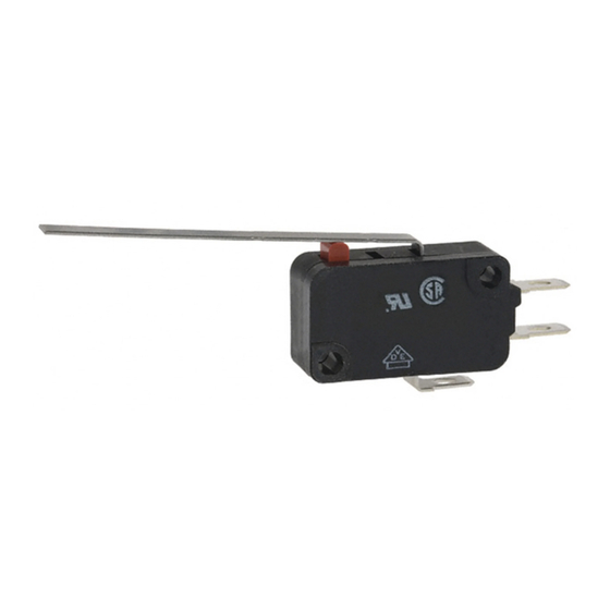
Miniature Basic Switch
Miniature Basic Switch with Low
Operating Force and High Contact
Reliability
Wide variation extends from micro load to 5-A
switching current, with shapes identical to those of
the V-series Miniature Basic Switch.
A unique internal mechanism enables high contact
strength with low operating force. Can be used for
detecting lightweight objects.
Ordering Information
Model Number Legend
VX-jj-jjj
1
2
3
4
5
1.
Ratings
5:
5 A at 250 VAC
01: 0.1 A at 30 VDC
2.
Actuator
None: Pin plunger
1:
Short hinge lever
2:
Hinge lever
3:
Long hinge lever
4:
Simulated roller lever
5:
Short hinge roller lever
6:
Hinge roller lever
126
3.
Contact Form
1:
SPDT
2:
SPST-NC
3:
SPST-NO
4.
Terminals
A:
Solder terminals
C2: Quick-connect terminals (#187)
5.
Maximum Operating Force
2:
OF 0.25 N {25 gf}
3:
OF 0.49 N {50 gf}
Note:
These values are for the pin plunger models.
VX
RCW
Advertisement
Table of Contents

Subscribe to Our Youtube Channel
Related Manuals for Omron VX Series


Summary of Contents for Omron VX Series
- Page 1 Miniature Basic Switch Miniature Basic Switch with Low Operating Force and High Contact Reliability Wide variation extends from micro load to 5-A switching current, with shapes identical to those of the V-series Miniature Basic Switch. A unique internal mechanism enables high contact strength with low operating force.
-
Page 2: List Of Models
VX-55-1C23 VX-015-1C23 Hinge roller lever 0.29 N {30 gf} VX-56-1A3 VX-016-1A3 VX-56-1C23 VX-016-1C23 Note: 1. Contact your OMRON sales representative for details on SPST-NO and SPST-NC models. 2. Terminals A: Solder terminals Quick-connect terminals (#187) Specifications Ratings Item Resistive load... - Page 3 3. For the pin plunger models, the above values apply for use at both the free position and total travel position. For the lever models, they apply at the total travel position. Contact opening or closing time is within 1 ms. 4. For testing conditions, contact your OMRON sales representative. Approved Standards Consult your OMRON sales representative for specific models with EN61058-1 (File No.
- Page 4 Engineering Data (Reference Values) Mechanical Durability (Pin Plunger Models) VX-01 VX-5 Ambient temperature: 20±2°C Ambient temperature: 20±2°C Ambient humidity: 65±5% Ambient humidity: 65±5% Without load Without load Operating frequency: 600 operations/min Operating frequency: 600 operations/min Full stroke Rated value of OT Full stroke Rated value of OT...
-
Page 5: Mounting Holes
Dimensions Terminals Note: 1. All units are in millimeters unless otherwise indicated. 2. The following is for the SPDT contact specifications. Terminal type Solder terminals (A) Quick-connect terminals (#187) (C2) COM bottom position (5.5) (5.5) (6.5) (6.5) (10) (10) t=0.5 t=0.5 Three, quick-connect terminals (#187) Three, solder terminals... - Page 6 Hinge Lever Models Model VX-52-1j3 VX-012-1j3 t = 0.5 (stainless-steel lever) VX-52-1j3 OF max. 0.29 N {30 gf} +0.13 35.6±0.8 dia. holes VX-012-1j3 –0.03 RF min. PT max. 4.0 mm 10.3±0.1 OT min. 1.6 mm 15.9 18.8 MD max. 0.8 mm +0.13 –0.03 15.2±1.2 mm...
- Page 7 Hinge Roller Lever Models Model VX-56-1j3 VX-016-1j3 4.8 dia. × 4.8 VX-56-1j3 OF max. 0.29 N {30 gf} (oilless polyacetar resin roller) VX-016-1j3 t = 0.5 (stainless-steel lever) 34.0±0.8 RF min. +0.13 dia. holes –0.03 PT max. 4.0 mm OT min. 1.6 mm 10.3±0.1 MD max.
- Page 8 General Information General Information Correct Use Electrical Conditions Area Item Page Load Using Switches The switching capacity of a switch significantly differs depending on Selecting Correct Switch whether the switch is used to break an alternating current or a direct Electrical Load current.
-
Page 9: General Information
General Information General Information Contact Protective Circuit Apply a contact protective circuit (surge killer) to extend contact du- When a switch is used under high humidity, arcs resulting from cer- rability, prevent noise, and suppress the generation of carbide or ni- tain types of load (e.g., inductive loads) will generate nitrious oxides tric acid due to arc. -
Page 10: Mechanical Conditions
General Information General Information Mechanical Conditions Switching Speed and Frequency The switching frequency and speed of a switch have a great influ- Operating Stroke Setting ence on the performance of the switch. Pay attention to the follow- The setting of stroke is very important for a switch to operate with ing. -
Page 11: Terminal Connections
General Information General Information • Incorrect Do not modify the actuator. If the actuator is modified, excessive external force may be applied to the internal switch mechanism, Snap-back characteristics may change, and the switch may stop Shock operation functioning. • If an external actuator is used as an operating object, check the material and thickness of the lever to make sure that the force applied to the lever is within the permissible range. - Page 12 General Information General Information terminals, otherwise the terminal may be deformed or the housing Operation and Storage Environment may be damaged. Handling Wiring Work Do not apply oil, grease, or other lubricants to the sliding parts of a When wiring a switch, check the insulation distance between the switch.
- Page 13 General Information General Information Switch Trouble and Corrective Action Type Location Failure Possible cause Corrective action of failure Failures Contact Contact Dust and dirt on the contacts. Remove the cause of the problem, place related to l t d t f il failure the switch in a box, or use a sealed...
- Page 14 2. Unless otherwise specified, a tolerance of ±0.4 mm applies to all dimensions. 3. For operating characteristics of models not listed above, consult your OMRON sales representative. 4. The operating characteristics are for operation in the A direction ( ).
- Page 15 D3V/V/VX/D2MV/K/D2RV D3V/V/VX/D2MV/K/D2RV Simulated Leaf Spring In the case of V-15-1A5 VAL12 (Designed for models of OF 200 gf and greater) OF max. 2.26 N {230 gf} RF min. 0.49 N {50 gf} t=0.3, (Stainless-steel spring lever) OT min. 0.8 mm 2.4R MD max.
- Page 16 D3V/V/VX/D2MV/K/D2RV D3V/V/VX/D2MV/K/D2RV Hinge Roller Lever In the case of V-15-1A5 VAV2 4.8 dia. 4.8 (Unlubricated polyacetal resin roller) OF max. 0.74 N {75 gf} RF min. 0.09 N {9 gf} PT max. 4.8 mm OT min OT min. 1 5 mm 1.5 mm MD max.
- Page 17 D3V/V/VX/D2MV/K/D2RV D3V/V/VX/D2MV/K/D2RV Reverse Hinge Roller Lever In the case of V-15-1A5 9.5 dia. 4.8. VAM22 (Stainless- OF max. 3.53 N {360 gf} steel roller) RF min. 0.69 N {70 gf} OT min. 3 mm (reference value) (reference value) MD max. 4 mm FP max.
- Page 18 Connectors Connectors Connectors Microswitches for tab-terminals listed in this catalog are compatible with other companies‘ products. The following AMP-made Connectors are also available. For more details about AMP Connectors, contact one of the addresses listed below. Tyco Electronics/AMP • • Japan Great Britain Phone: 81-44-844-8013...
Need help?
Do you have a question about the VX Series and is the answer not in the manual?
Questions and answers