Advertisement
Quick Links
2219498-9 A
EU
EU
Instructions in the official EU languages and a signed EC Declaration of Conformity in English are available on our website at www.industrial.omron.eu/safety.
E
C
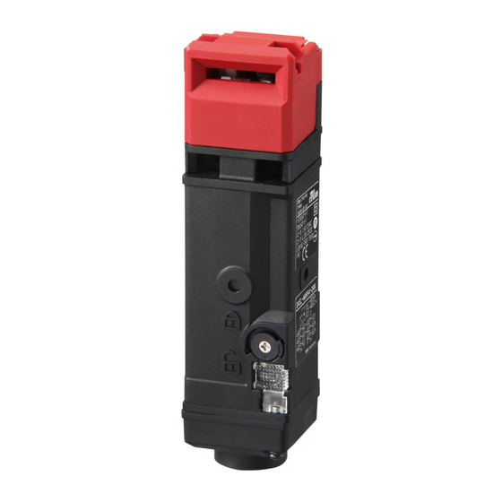
D4SL-N
EC
2006/42/EC
EMC
2004/108/EC
2219498-9 A
EU
EU
Instructions in the official EU languages and a signed EC Declaration of Conformity in English are available on our website at www.industrial.omron.eu/safety.
E
C
D4SL-N
EC
2006/42/EC
EMC
2004/108/EC
(
)
(
)
IP67
1.5 2
IP67
EN
IEC60127
4A
(AC125V,1A)
3
9mm
1.5 2
EN
IEC60127
4A
1/2-14NPT
(AC125V,1A)
3
9mm
1/2-14NPT
(
(
(H
S SO
NH
HNO
Cl
)
2
2
3
3
2
(H
S SO
NH
HNO
Cl
)
2
2
3
3
2
H
S SO
NH
HNO
Cl
2
2
3
3
2
6
1
H
S SO
NH
HNO
Cl
2
2
3
3
2
LOCK
UNLOCK
6
1
UNLOCK
LOCK
LOCK
UNLOCK
D4SL-N
A
UNLOCK
D4SL-N
UNLOCK
G
LOCK
LOCK
UNLOCK
D4SL-N
A
UNLOCK
D4SL-N
G
LOCK
UNLOCK
0.2N m
0.2N m
0.5 0.6 N m
0.4 0.5 N m
0.5 0.6 N m
D4SL-NK G
0.75 1.15 N m
0.4 0.5 N m
D4SL-NK
NK S
2.4 2.8 N m
D4SL-NK G
0.75 1.15 N m
0.75 1.15 N m
D4SL-NK
NK S
2.4 2.8 N m
1.8 2.2 N m G1/2 M20
0.75 1.15 N m
1.4 1.8 N m 1/2-14NPT
1.8 2.2 N m G1/2 M20
2
1.4 1.8 N m 1/2-14NPT
M4
2
M4
4±0.1
1.5
4±0.1
1.5
D4SL-N
-
D4SL-N
- 4
D4SL-N
-
D4SL-N
- 4
Front
Front
LOCK
LOCK
LOCK
LOCK
41.7±0.15
41.7±0.15
Side
Side
38.7±0.1
38.7±0.1
UNLOCK
UNLOCK
41.7±0.15
UNLOCK
UNLOCK
41.7±0.15
1 Fig.1
1 Fig.1
1 Fig.1
Guard Lock Safety-door Switch
Manvel d'Instrvctions
Instruction Sheet
manuale d'Instruzioni
Bertriebsanleitung
manuale de Instrucciones
www.industrial.omron.eu/safety.
Guard Lock Safety-door Switch
(D4SL-NK )
Manvel d'Instrvctions
0.8mm
Instruction Sheet
manuale d'Instruzioni
Bertriebsanleitung
manuale de Instrucciones
3
www.industrial.omron.eu/safety.
D4SL-K
(D4SL-NK )
3
0.8mm
4
3
5
D4SL-K
3
NC
4
DC24V
E1
DC24V
5
6
.
NC
AWG22 18 0.3 0.75mm
DC24V
E1
E2
DC24V
6
.
AI0.34-8 TQ
AWG22
AWG22 18 0.3 0.75mm
2
L1
PHOENIX
AI0.5-8 WH
AWG20
L2
CONTACT
AI0.75-8 GY
AWG18
1/2-14NPT
IP67
AI0.34-8 TQ
AWG22
L1
14mm
PHOENIX
L2
8mm
AI0.5-8 WH
AWG20
CONTACT
AI0.75-8 GY
AWG18
9mm
9mm
IP67
1/2-14NPT
IP67
LAPP
ST-PF1/2
5380-1002
G1/2
LS-2G
M20
LAPP
ST-M20×1.5 5311-1020
9mm
1/2-14NPT LAPP
9mm
ST-NPT1/2
5301-6030
IP67
JPK-16
GPM20
LAPP
ST-PF1/2
5380-1002
6.0 12.0mm
LAPP
G1/2
LS-2G
http://www.ace-service.co.jp
6.0 11.0mm
1/2-14NPT
M20
LAPP
ST-M20×1.5 5311-1020
7.0 13.0mm
1/2-14NPT LAPP
ST-NPT1/2
5301-6030
6.0 12.0mm
JPK-16
GPM20
LAPP
TEL 043 423 8741
EMC
EN1088 EN50047 GS-ET-19
http://www.ace-service.co.jp
EN60947-5-1 IEC60947-5-1, UL508 CSA C22.2 No.14
1/2-14NPT
EN
UL CSA
AC-15
DC-13
AC120V
DC125V
1.5A
0.22A
EMC
EN1088 EN50047 GS-ET-19
EN60947-5-1 IEC60947-5-1, UL508 CSA C22.2 No.14
EN
(
) 15mm
UL CSA
AC-15
DC-13
C150
(
) 60N
AC120V
DC125V
AC120V
1300N GS-ET-19
1.5A
0.22A
1800VA
0.05 1m/s
180VA
5
/
100A
(
) 15mm
4A
(IEC60127)
(
) 60N
IP67(EN60947-5-1) (
1300N GS-ET-19
TYPE 4X INDOOR USE ONLY (UL, CSA)
0.05 1m/s
DC5V 1mA
(
)
5
/
100A
10
55
(
95 RH
4A
(IEC60127)
IP67(EN60947-5-1) (
100
TYPE 4X INDOOR USE ONLY (UL, CSA)
15
(AC125
1A
DC5V 1mA
(
)
DC24V+10 /-15
10
55
(
)
-
95 RH
D4SL-N |N/P/Q/R|
100
D4SL-N |
|
15
(AC125
1A
)
2.6W
DC24V+10 /-15
(LED)
DC24V
10mA
-
B10d 2,000,000
D4SL-N |N/P/Q/R|
-
ON/OFF
D4SL-N |
|
-
2.6W
0.15A
(LED)
DC24V
10mA
B10d 2,000,000
ON/OFF
a)
b)
a)
c)
d)
24
b)
e)
c)
*
d)
24
e)
*
LOCK
0120-919-066
LOCK
0120-919-066
PHS
PHS
055-982-5015
055-982-5015
8 00 21 00
365
FA
8 00 21 00
365
055-977-6389
FA
055-977-6389
9 00 12 00/13 00 17 30
9 00 12 00/13 00 17 30
FAX
FAX
FAX 055-982-5051
FAX 055-982-5051
D4SL-NK1/-NK1S/-NK2
M4
M4
D4SL-NK1/-NK1S/-NK2
2-M4
2-M4
22±0.1
22±0.1
15±0.1
15±0.1
±
4±0.1 dia. 1.5mm high max
4±0.1 dia. 1.5mm high max
D4SL-NK1G/-NK2G
D4SL-NK1G/-NK2G
10±0.1
2-M4
10±0.1
2-M4
±
12±0.1
12±0.1
M4
or 20±0.1
M4
or 20±0.1
22±0.1
D4SL-NK3
22±0.1
2-M4
D4SL-NK3
2-M4
±
4±0.1 dia. 1.5mm high max
40±0.1
4±0.1 dia. 1.5mm high max
40±0.1
2 Fig.2
3 Fig.3
3 Fig.3
2 Fig.2
2 Fig.2
3 Fig.3
Original instruction
EC Declaration of Conformity
OMRON declares that D4SL-N is in conformity with the requirements of the
following EC Directives:
Thank you for purchasing this D4SL-N. This INSTRUCTION MANUAL described the information such as
Machinery Directive 2006/42/EC
function, performance and how to use the product required for using the D4SL-N.
EMC Directive 2004/108/EC
For using this product, please follow keep the precautions as shown in the following:
Ensure that this product is installed and operated by qualified personal having sufficient skills in
Safety Precaution
mechanics and electrotechnic.
Definition of Precautionary Information
Ensure that you understood this manual and that you use the product as described in this manual.
Keep this instruction manual close at hand and use it for reference during operation.
Indicates an imminently hazardous situation
which, if not avoided, is likely to result in serious
Original instruction
DANGER
Thank you for purchasing this
injury or may result in death. Additionally there
EC Declaration of Conformity
function, performance and how to use the product required for using the
may be severe property damage.
For using this product, please follow keep the precautions as shown in the following:
OMRON declares that D4SL-N is in conformity with the requirements of the
Ensure that this product is installed and operated by qualified personal having sufficient skills in
following EC Directives:
Indicates a potentially hazardous situation
mechanics and electrotechnic.
Machinery Directive 2006/42/EC
Ensure that you understood this manual and that you use the product as described in this manual.
which, if not avoided, may result in minor or
EMC Directive 2004/108/EC
CAUTION
Keep this instruction manual close at hand and use it for reference during operation.
moderate injury or in property damage.
Safety Precaution
Original instruction
Definition of Precautionary Information
Precautionary Information
Indicates an imminently hazardous situation
OMRON declares that D4SL-N is in conformity with the requirements of the
which, if not avoided, is likely to result in serious
DANGER
following EC Directives:
injury or may result in death. Additionally there
Machinery Directive 2006/42/EC
Always verify the operation of the safety functions
may be severe property damage.
EMC Directive 2004/108/EC
before starting the system.Not do so may result that
Indicates a potentially hazardous situation
the safety functions may not be performed as expected
which, if not avoided, may result in minor or
CAUTION
if wiring or settings are incorrect or the switch have
E2
moderate injury or in property damage.
failed.The controlled system may continue to operate
and possibly resulting in injury or death.
Precautionary Information
DANGER
Always verify the operation of the safety functions
before starting the system.Not do so may result that
Do not dismount the operation key from the door
the safety functions may not be performed as expected
intentionally and insert it to the switch with the door
if wiring or settings are incorrect or the switch have
2
open. Machine may start operating and injury or death
failed.The controlled system may continue to operate
may be caused.
and possibly resulting in injury or death.
Do not apply force exceeding the specified maximum
holding force. Doing so may damage the switch lock
CAUTION
mechanism and the system may continue to operate,
possibly resulting in injury or death. Either install another
Do not dismount the operation key from the door
locking component (e.g., a hook) in addition to the
intentionally and insert it to the switch with the door
Switch, or use a warning measures or an indicator
14mm
open. Machine may start operating and injury or death
showing the controlled system is locked to avoid
8mm
may be caused.
overloading the holding force in lock mode.
Do not apply force exceeding the specified maximum
holding force. Doing so may damage the switch lock
Precautions for Safe Use
mechanism and the system may continue to operate,
1. Environment
possibly resulting in injury or death. Either install another
1-1. Do not use the switch where explosive gas, ignitable gas, or any other harmful
locking component (e.g., a hook) in addition to the
gasses may be present.
Switch, or use a warning measures or an indicator
1-2. Do not use the switch in the oil and in the water. IP67 (EN60947-5-1)
1-3. Though the switch body is protected from the ingress of dust or water, avoid
showing the controlled system is locked to avoid
the ingress of foreign substance through the key hole on the head.
overloading the holding force in lock mode.
Otherwise, wear in short time or break may be caused
2. Wiring
Precautions for Safe Use
2-1. Connect the fuse to the switch in series to prevent it from short circuit damage.
1. Environment
The value of the breaking current of the fuse must be increased to cover the
1-1. Do not use the switch where explosive gas, ignitable gas, or any other harmful
rated current by 150 to 200%. When using the switch with EN rating, use 4 A
gasses may be present.
6.0 12.0mm
fast acting fuse that complies with IEC 60127.
1-2. Do not use the switch in the oil and in the water. IP67 (EN60947-5-1)
2-2. On the switching of general loads (125VAC/1A), do not operate three circuits or
1-3. Though the switch body is protected from the ingress of dust or water, avoid
6.0 11.0mm
more at the same time. Otherwise, insulation performance may be degraded .
the ingress of foreign substance through the key hole on the head.
2-3. Keep the electrical load below the rated value.
7.0 13.0mm
Otherwise, wear in short time or break may be caused
1. Environment
2. Wiring
2-4.Use a metallic connector which has a threaded portion of 9 mm length or less.
6.0 12.0mm
1-1. Do not use the switch where explosive gas, ignitable gas, or any other harmful
2-1. Connect the fuse to the switch in series to prevent it from short circuit damage.
2-5. Do not use metal conduit with this switch. The broken conduit hole may cause
gasses may be present.
The value of the breaking current of the fuse must be increased to cover the
electrical shock hazard.
1-2. Do not use the switch in the oil and in the water. IP67 (EN60947-5-1)
rated current by 150 to 200%. When using the switch with EN rating, use 4 A
2-6.Use of a 1/2-14NPT connector may result in damage to a conversion adapter,
1-3. Though the switch body is protected from the ingress of dust or water, avoid
TEL 043 423 8741
the ingress of foreign substance through the key hole on the head.
fast acting fuse that complies with IEC 60127.
causing defective sealing or a risk of electric shock. Do not use metallic
Otherwise, wear in short time or break may be caused
2-2. On the switching of general loads (125VAC/1A), do not operate three circuits or
connectors.
2. Wiring
more at the same time. Otherwise, insulation performance may be degraded .
2-7. Be sure to install a cover after the wiring.
2-1. Connect the fuse to the switch in series to prevent it from short circuit damage.
2-3. Keep the electrical load below the rated value.
Do not put the electric power when opening a cover.
The value of the breaking current of the fuse must be increased to cover the
2-4.Use a metallic connector which has a threaded portion of 9 mm length or less.
Do not put the electric power when wiring.
rated current by 150 to 200%. When using the switch with EN rating, use 4 A
2-5. Do not use metal conduit with this switch. The broken conduit hole may cause
2-8. Make sure that foreign substance does not adhere to the board.. A short-circuit between board
fast acting fuse that complies with IEC 60127.
electrical shock hazard.
2-2. On the switching of general loads (125VAC/1A), do not operate three circuits or
terminals may occur, causing the safety functions disabled.
2-6.Use of a 1/2-14NPT connector may result in damage to a conversion adapter,
more at the same time. Otherwise, insulation performance may be degraded.
3. Mounting
causing defective sealing or a risk of electric shock. Do not use metallic
2-3. Keep the electrical load below the rated value.
3-1. Be careful not to drop your D4SL-N, or the switch will
connectors.
2-4.Use a metallic connector which has a threaded portion of 9 mm length or less.
not fully exhibit its ability.
2-7. Be sure to install a cover after the wiring.
2-5. Do not use metal conduit with this switch. The broken conduit hole may cause
Do not put the electric power when opening a cover.
3-2. This may cause a risk of personal injury.
electrical shock hazard.
C150
R150
Do not put the electric power when wiring.
Extra care must be taken not to drop this Product
2-6.Use of a 1/2-14NPT connector may result in damage to a conversion adapter,
AC120V
DC125V
2-8. Make sure that foreign substance does not adhere to the board.. A short-circuit between board
during installation..
causing defective sealing or a risk of electric shock. Do not use metallic
1800VA
28VA
terminals may occur, causing the safety functions disabled.
3-3. Install operation key so that it will not hit the operator
connectors.
3. Mounting
180VA
28VA
when the door is open. Injury may be caused.
2-7. Be sure to install a cover after the wiring.
3-1. Be careful not to drop your D4SL-N, or the switch will
Do not put the electric power when opening a cover.
3-4.Do not use the switch as a stopper.
not fully exhibit its ability.
Do not put the electric power when wiring.
Be sure to install a stopper as shown in the following
3-2. This may cause a risk of personal injury.
2-8. Make sure that foreign substance does not adhere to the board.. A short-circuit between board
illustration to prevent the edge of the operation key
R150
Extra care must be taken not to drop this Product
terminals may occur, causing the safety functions disabled.
from inadvertently hitting the switch directly.
DC125V
3. Mounting
during installation..
4. Others
28VA
3-3. Install operation key so that it will not hit the operator
3-1. Be careful not to drop your
D4SL-N,
or the switch will
4-1. Do not disassemble or remodel your D4SL-N in any case, or the D4SL-N will
28VA
not fully exhibit its ability.
when the door is open. Injury may be caused.
not operate normally.
3-2. This may cause a risk of personal injury.
3-4.Do not use the switch as a stopper.
4-2. Evaluate the switch under actual working conditions before permanent
Extra care must be taken not to drop this Product
Be sure to install a stopper as shown in the following
during installation..
installation.
illustration to prevent the edge of the operation key
3-3. Install operation key so that it will not hit the operator
The durability of the switch is seriously affected by operating conditions.
from inadvertently hitting the switch directly.
IP00)
when the door is open. Injury may be caused.
4. Others
4-3. Please mention in machine manufacturer's Instruction.
3-4.Do not use the switch as a stopper.
4-1. Do not disassemble or remodel your D4SL-N in any case, or the D4SL-N will
Manual that the user must not repair nor maintain the switch and must
Be sure to install a stopper as shown in the following
not operate normally.
contact machine manufacturer for them.
illustration to prevent the edge of the operation key
4-2. Evaluate the switch under actual working conditions before permanent
)
from inadvertently hitting the switch directly.
Precautions for Correct Use
installation.
4. Others
The durability of the switch is seriously affected by operating conditions.
1. About the solenoid lock type
4-1. Do not disassemble or remodel your
D4SL-N
in any case, or the
IP00)
4-3. Please mention in machine manufacturer's Instruction.
1-1. Be sure to energize the solenoid with the door closed (with the operation key
not operate normally.
)
Manual that the user must not repair nor maintain the switch and must
4-2. Evaluate the switch under actual working conditions before permanent
inserted). A malfunction will occur in Solenoid lock when energizing the
contact machine manufacturer for them.
installation.
solenoid before closing the door.
The durability of the switch is seriously affected by operating conditions.
1-2. In the solenoid lock type, a lock is closed only when the solenoids are energized.
Precautions for Correct Use
4-3. Please mention in machine manufacturer's Instruction.
-
6.4W-0.27A
A lock may be opened when the passage of an electric current to the solenoid is
1. About the solenoid lock type
Manual that the user must not repair nor maintain the switch and must
stopped due to sudden power failure. Do not use the solenoid lock type for the
-
4.8W-0.2A
1-1. Be sure to energize the solenoid with the door closed (with the operation key
contact machine manufacturer for them.
machine in which the inside of the door remains dangerous even after
inserted). A malfunction will occur in Solenoid lock when energizing the
0.15A
solenoid before closing the door.
shutdown of the machine.
1-2. In the solenoid lock type, a lock is closed only when the solenoids are energized.
2. Environment
1. About the solenoid lock type
1-1.
Be sure to energize the solenoid with the door closed (with the operation key
A lock may be opened when the passage of an electric current to the solenoid is
2-1. The switch is intended for indoor use only.
6.4W-0.27A
inserted). A malfunction will occur in Solenoid lock when energizing the
stopped due to sudden power failure. Do not use the solenoid lock type for the
4.8W-0.2A
2-2. Do not use your D4SL-N outdoor, or the switch will malfunction.
solenoid before closing the door.
machine in which the inside of the door remains dangerous even after
2-3. Do not use your D4SL-N in the atmosphere of hazardous gases (H
1-2. In the solenoid lock type, a lock is closed only when the solenoids are energized.
shutdown of the machine.
HNO
, CI
, etc.) or high temperature and humidity, or it will cause the
3
2
A lock may be opened when the passage of an electric current to the solenoid is
2. Environment
imperfect closing of the contacts or the breakage thereof stemming from
stopped due to sudden power failure. Do not use the solenoid lock type for the
2-1. The switch is intended for indoor use only.
corrosion.
machine in which the inside of the door remains dangerous even after
2-2. Do not use your D4SL-N outdoor, or the switch will malfunction.
2-4. Do not use the switch under any of the conditions mentioned below.
shutdown of the machine.
2-3. Do not use your D4SL-N in the atmosphere of hazardous gases (H
2. Environment
Frequent temperature range.
HNO
, CI
, etc.) or high temperature and humidity, or it will cause the
3
2
2-1. The switch is intended for indoor use only.
High humidity or dew condensation may be generated.
imperfect closing of the contacts or the breakage thereof stemming from
2-2. Do not use your D4SL-N outdoor, or the switch will malfunction.
Where the switch is subject to severe vibration.
corrosion.
2-3. Do not use your D4SL-N in the atmosphere of hazardous gases (H
Where the metal dust, oil, or chemical is sprayed inside the door.
2-4. Do not use the switch under any of the conditions mentioned below.
HNO
, CI
, etc.) or high temperature and humidity, or it will cause the
3
2
Where thinner is applied.
Frequent temperature range.
imperfect closing of the contacts or the breakage thereof stemming from
3. Storage
High humidity or dew condensation may be generated.
corrosion.
Where the switch is subject to severe vibration.
3-1. Do not keep the switch in dusty, humid place and any place where gas may be
2-4. Do not use the switch under any of the conditions mentioned below.
Where the metal dust, oil, or chemical is sprayed inside the door.
present for example H
S, SO
Frequent temperature range.
2
Where thinner is applied.
3-2. A switch that has been stored for more than six months must be checked again
High humidity or dew condensation may be generated.
3. Storage
Where the switch is subject to severe vibration.
before use.
3-1. Do not keep the switch in dusty, humid place and any place where gas may be
Where the metal dust, oil, or chemical is sprayed inside the door.
4. Using the release key (See Figure 1)
present for example H
S, SO
, NH
, HNO
Where thinner is applied.
4-1. The release key is used to open a lock in the case of power failure or
2
2
3
3. Storage
3-2. A switch that has been stored for more than six months must be checked again
emergency.
3-1. Do not keep the switch in dusty, humid place and any place where gas may be
before use.
4-2. Turn the release key from the LOCK position to the UNLOCK position to
present for example H
S, SO
, NH
, HNO
, Cl
..
4. Using the release key (See Figure 1)
2
2
3
3
2
release the lock. This can open the safety door. (For the mechanical lock type
3-2. A switch that has been stored for more than six months must be checked again
4-1. The release key is used to open a lock in the case of power failure or
only.)
before use.
emergency.
4. Using the release key (See Figure 1)
4.3. When the release key is turned to the UNLOCK position for maintenance or
4-2. Turn the release key from the LOCK position to the UNLOCK position to
4-1. The release key is used to open a lock in the case of power failure or
other purposes, make sure to turn it back to the LOCK position before using it.
release the lock. This can open the safety door. (For the mechanical lock type
emergency.
4-4. The set position of the release key at the shipping of the switch is as noted
only.)
4-2. Turn the release key from the LOCK position to the UNLOCK position to
4.3. When the release key is turned to the UNLOCK position for maintenance or
below;
release the lock. This can open the safety door. (For the mechanical lock type
other purposes, make sure to turn it back to the LOCK position before using it.
D4SL-N
A : UNLOCK position
only.)
4-4. The set position of the release key at the shipping of the switch is as noted
4-5. While the release key is in the UNLOCK position, a lock is not closed and a
4.3. When the release key is turned to the UNLOCK position for maintenance or
below;
machine is not activated even when the door is closed in the course of
other purposes, make sure to turn it back to the LOCK position before using it.
D4SL-N
A : UNLOCK position
preliminary adjustment work performed inside a large ma chine or a
4-4. The set position of the release key at the shipping of the switch is as noted
4-5. While the release key is in the UNLOCK position, a lock is not closed and a
depressing type machine.
below;
machine is not activated even when the door is closed in the course of
D4SL-N
A
: UNLOCK position
D4SL-N
4-6. Do not use the release key when starting or stopping the machine.
preliminary adjustment work performed inside a large ma chine or a
4-5. While the release key is in the UNLOCK position, a lock is not closed and a
4-7. The releasing of the auxiliary lock must be handled by an authorized person.
depressing type machine.
machine is not activated even when the door is closed in the course of
4-8. Do not apply an excessive force (of 0.2N m or more) to the threaded portion of
4-6. Do not use the release key when starting or stopping the machine.
preliminary adjustment work performed inside a large machine or a
the release key. The release key may be damaged to the extent that it no
4-7. The releasing of the auxiliary lock must be handled by an authorized person.
depressing type machine.
longer becomes operational.
4-8. Do not apply an excessive force (of 0.2N m or more) to the threaded portion of
4-6. Do not use the release key when starting or stopping the machine.
4-9. To avoid an unauthorized person's access to the release mechanism, set the
4-7. The releasing of the auxiliary lock must be handled by an authorized person.
the release key. The release key may be damaged to the extent that it no
release key to the LOCK position, and then seal the release key with a seal
4-8. Do not apply an excessive force (of 0.2N m or more) to the threaded portion of
longer becomes operational.
the release key. The release key may be damaged to the extent that it no
wax (or wax coatings).
4-9. To avoid an unauthorized person's access to the release mechanism, set the
longer becomes operational.
release key to the LOCK position, and then seal the release key with a seal
5. Installing the cover
4-9. To avoid an unauthorized person's access to the release mechanism, set the
wax (or wax coatings).
5-1. Confirm that the seal rubber has no abnormality and then use it.
release key to the LOCK position, and then seal the release key with a seal
5. Installing the cover
If the seal rubber is displaced or floated, or if foreign matters adhere to the seal
wax (or wax coatings).
5-1. Confirm that the seal rubber has no abnormality and then use it.
rubber, the seal rubber will lose its sealing capability.
5. Installing the cover
If the seal rubber is displaced or floated, or if foreign matters adhere to the seal
5-2. Do not use any screw other than correct one, or the sealing capability of the
5-1. Confirm that the seal rubber has no abnormality and then use it.
rubber, the seal rubber will lose its sealing capability.
seal rubber will deteriorate.
If the seal rubber is displaced or floated, or if foreign matters adhere to the seal
5-2. Do not use any screw other than correct one, or the sealing capability of the
6. About the hinge type door
rubber, the seal rubber will lose its sealing capability.
seal rubber will deteriorate.
6-1. A door is mounted near a hinge, excessive load may be imposed beyond a force
5-2. Do not use any screw other than correct one, or the sealing capability of the
6. About the hinge type door
seal rubber will deteriorate.
acting on the lock portion of this Equipment. This may result in damage to the
6-1. A door is mounted near a hinge, excessive load may be imposed beyond a force
6. About the hinge type door
lock mechanism. Mount it to a position near a handle.
acting on the lock portion of this Equipment. This may result in damage to the
6-1. A door is mounted near a hinge, excessive load may be imposed beyond a force
7. Mounting method
lock mechanism. Mount it to a position near a handle.
acting on the lock portion of this Equipment. This may result in damage to the
7-1. Mounting screw tightening torque loose mounting may result in malfunction.
7. Mounting method
lock mechanism. Mount it to a position near a handle.
Fasten the screws to the specified torque.
7-1. Mounting screw tightening torque loose mounting may result in malfunction.
7. Mounting method
Fasten the screws to the specified torque.
Terminal screw
7-1. Mounting screw tightening torque loose mounting may result in malfunction.
Terminal screw
Fasten the screws to the specified torque.
Cover clamping screw
T
r e
m
n i
l a
Cover clamping screw
c s
e r
w
Operation key clamping screw (D4SL-NK G
C
v o
r e
c
a l
Operation key clamping screw (D4SL-NK G
m
p
n i
g
c s
e r
w
Operation key clamping screw
Operation key clamping screw
(D4SL-NK G
Operation key clamping screw
(D4SL-NK ,NK S)
Operation key clamping screw
(D4SL-NK ,NK S)
Body clamping screw
(D4SL-NK ,NK S)
Body clamping screw
Body clamping screw
Conduit mounting connection
Conduit mounting connection
Conduit mounting connection
for D4SL-N N
-D
for D4SL-N N
-D
for D4SL-N N
-D
E1
E1
9
9
E1
( )
( )
( )
Door Open/Close
LED
LED
LED
E2
E2
Detection Switch)
E2
10
10
( )
( )
( )
42
41
12
42
2
41
12
42
11
41
2
52
51
22
52
51
22
21
4
52
51
4
64
64
63
34
63
34
33
8
64
8
7
6
Lock M onitor Switch)
Lock M onitor Switch)
Lock M onitor Switch)
4 Fig.4
4 Fig.4
4 Fig.4
Thank you for purchasing this D4SL-N. This INSTRUCTION MANUAL described the information such as
function, performance and how to use the product required for using the D4SL-N.
For using this product, please follow keep the precautions as shown in the following:
Ensure that this product is installed and operated by qualified personal having sufficient skills in
mechanics and electrotechnic.
Ensure that you understood this manual and that you use the product as described in this manual.
Keep this instruction manual close at hand and use it for reference during operation.
7-2. Switch, operation key (See Figure 2)
1) The switch and operation key will be fastened to specified torque in clause 7-1
with M4 screws and washers.
2) The switch can be fastened more firmly by a stud(4mm dia., 1.5mm max height)
inserted from back side at the hole of the switch.
3) Do not use the operation key other than dedicated OMRON's (D4SL-NK ).
Otherwise switch may be damaged.
4) Be sure that the operation key can be inserted properly to key hole with a
tolerance of ± 0.8mm.
5) Insert the operation key into the key hole according to the specified "operation
key insertion radius in horizontal direction ".
6) Do not impose excessive force on the key top while the operation key is inserted
into the switch body or drop the switch with the operation key inserted to avoid
7-2. Switch, operation key (See Figure 2)
D4SL-N.
This INSTRUCTION MANUAL described the information such as
the deformation of the key or the breakage of the switch body.
1) The switch and operation key will be fastened to specified torque in clause 7-1
D4SL-N.
with M4 screws and washers.
7) When mounting at the side of switch body, mount the switch with 3 points
2) The switch can be fastened more firmly by a stud(4mm dia., 1.5mm max height)
including the head.
inserted from back side at the hole of the switch.
8) Attach cap heads to any operation key holes that are not being used.
3) Do not use the operation key other than dedicated OMRON's (D4SL-NK ).
9) Do not use the operation key D4SL-K . A lock will not be closed and a machine
Otherwise switch may be damaged.
will not be activated.
4) Be sure that the operation key can be inserted properly to key hole with a
7-3. Securing of the door (See Figure 3)
tolerance of ± 0.8mm.
1) If the operation key is pulled in the opening direction due to a force caused by
7-2. Switch, operation key (See Figure 2)
5) Insert the operation key into the key hole according to the specified "operation
vibration, by the door weight, or by a cushion attached to the door. The closed
1) The switch and operation key will be fastened to specified torque in clause 7-1
key insertion radius in horizontal direction ".
door must be secured with a hook or by similar means.
with M4 screws and washers.
6) Do not impose excessive force on the key top while the operation key is inserted
7-4. Spacer (See Figure 4)
DANGER
2) The switch can be fastened more firmly by a stud(4mm dia., 1.5mm max height)
into the switch body or drop the switch with the operation key inserted to avoid
inserted from back side at the hole of the switch.
1) Do not remove the spacer. Use the switch with the spacer rotated appropriate
the deformation of the key or the breakage of the switch body.
3) Do not use the operation key other than dedicated OMRON's
for the mounting direction. Lock strength will decrease when using the switch
7) When mounting at the side of switch body, mount the switch with 3 points
Otherwise switch may be damaged.
without spacer.
including the head.
4) Be sure that the operation key can be inserted properly to key hole with a
8. Wiring
8) Attach cap heads to any operation key holes that are not being used.
tolerance of
0.8mm.
9) Do not use the operation key D4SL-K . A lock will not be closed and a machine
8-1. Example of circuit connections (See Figure 5)
5) Insert the operation key into the key hole according to the specified "operation
will not be activated.
1).
Internal circuit of the switch inside is different according to the part
key insertion radius in horizontal direction".
7-3. Securing of the door (See Figure 3)
number. Please confirm the circuit diagram on the product body when
6) Do not impose excessive force on the key top while the operation key is inserted
1) If the operation key is pulled in the opening direction due to a force caused by
using.
into the switch body or drop the switch with the operation key inserted to avoid
vibration, by the door weight, or by a cushion attached to the door. The closed
the deformation of the key or the breakage of the switch body.
2). The open circuit operating contacts are labeled with arrow marks. They are
door must be secured with a hook or by similar means.
7) When mounting at the side of switch body, mount the switch with 3 points
able to used as input to the safety circuit.
7-4. Spacer (See Figure 4)
including the head.
Please make the system that can observe both the door open/close
3).
CAUTION
8) Attach cap heads to any operation key holes that are not being used.
1) Do not remove the spacer. Use the switch with the spacer rotated appropriate
detection switch and the lock monitor switch NC contacts close when
9) Do not use the operation key D4SL-K . A lock will not be closed and a machine
for the mounting direction. Lock strength will decrease when using the switch
the lock is necessary on safety.
will not be activated.
without spacer.
4). The 24VDC solenoid has a polarity. (E1: Positive (+) polarity, E2: Negative ( -)
7-3. Securing of the door (See Figure 3)
8. Wiring
polarity)
1) If the operation key is pulled in the opening direction due to a force caused by
8-1. Example of circuit connections (See Figure 5)
vibration, by the door weight, or by a cushion attached to the door. The closed
5). Current consumption of the solenoid is different in inrush and constant.
1).
Internal circuit of the switch inside is different according to the part
door must be secured with a hook or by similar means.
number. Please confirm the circuit diagram on the product body when
Apply the rated working voltage to the solenoid.
7-4. Spacer (See Figure 4)
using.
8-2. Wiring (See Figure 6)
1) Do not remove the spacer. Use the switch with the spacer rotated appropriate
2). The open circuit operating contacts are labeled with arrow marks. They are
1). Do not put the electric power when wiring.
for the mounting direction. Lock strength will decrease when using the switch
able to used as input to the safety circuit.
2). Do not let particles such as small piece of le ad wire in the switch body when
without spacer.
Please make the system that can observe both the door open/close
3).
wiring.
8. Wiring
detection switch and the lock monitor switch NC contacts close when
3). Install the wiring through a crimp-style terminal for an insulating tube so that
8-1. Example of circuit connections (See Figure 5)
the lock is necessary on safety.
the wires do not run over the case or cover.
1).
Internal circuit of the switch inside is different according to the part
4). The 24VDC solenoid has a polarity. (E1: Positive (+) polarity, E2: Negative ( -)
number. Please confirm the circuit diagram on the product body when
4). Adequate conductor size is AWG 22 to 18 (0.3 to 0.75mm
polarity)
using.
5). Wire leads as shown in the following figure. Otherwise, the switch cover does
5). Current consumption of the solenoid is different in inrush and constant.
2). The open circuit operating contacts are labeled with arrow marks. They are
not fit.
Apply the rated working voltage to the solenoid.
able to used as input to the safety circuit.
6). When wiring the D4SL-N, remove the terminal block board out of the D4SL-N.
8-2. Wiring (See Figure 6)
3).
Please make the system that can observe both the door open/close
After this, make sure to insert the connector.
detection switch and the lock monitor switch NC contacts close when
1). Do not put the electric power when wiring.
7). Do not pull on lead wires with excessive force. The wires m ay break.
the lock is necessary on safety.
2). Do not let particles such as small piece of le ad wire in the switch body when
4). The 24VDC solenoid has a polarity. (E1: Positive (+) polarity, E2: Negative (-)
wiring.
Recommended Crimp-Style Terminals
3). Install the wiring through a crimp-style terminal for an insulating tube so that
polarity)
the wires do not run over the case or cover.
Manufacturer
5). Current consumption of the solenoid is different in inrush and constant.
Apply the rated working voltage to the solenoid.
4). Adequate conductor size is AWG 22 to 18 (0.3 to 0.75mm
PHOENIX
8-2. Wiring (See Figure 6)
5). Wire leads as shown in the following figure. Otherwise, the switch cover does
1). Do not put the electric power when wiring.
not fit.
CONTACT
2). Do not let particles such as small piece of lead wire in the switch body when
6). When wiring the D4SL-N, remove the terminal block board out of the D4SL-N.
wiring.
After this, make sure to insert the connector.
3). Install the wiring through a crimp-style terminal for an insulating tube so that
L1
max. 14mm
7). Do not pull on lead wires with excessive force. The wires m ay break.
the wires do not run over the case or cover.
L2
max.
4). Adequate conductor size is AWG 22 to 18 (0.3 to 0.75mm
Recommended Crimp-Style Terminals
5). Wire leads as shown in the following figure. Otherwise, the switch cover does
Manufacturer
not fit.
AI0.34-8 TQ
6). When wiring the D4SL-N, remove the terminal block board out of the D4SL-N.
PHOENIX
9. Conduit opening
AI0.5-8 WH
After this, make sure to insert the connector.
CONTACT
1). Use the connectors recommended in clause 10 and tighten the connector with
7). Do not pull on lead wires with excessive force. The wires may break.
AI0.75-8 GY
specified torque in clause 7-1. An excessive torque will bring a case breakage.
Recommended Crimp-Style Terminals
2). When using the connector size of 1/2-14NPT, apply the sealing tape between
L1
max. 14mm
Manufacturer
Type
connector and conduit opening so that the enclosure will conform to IP67.
L2
max.
8mm
AI0.34-8 TQ
3). Use a cable with a suitable diameter for the connector.
PHOENIX
AI0.5-8 WH
10. Recommendation of connector
CONTACT
AI0.75-8 GY
For easy wiring, use a connector that has the screw part with 9 mm or less in
9. Conduit opening
length.
L1
max. 14mm
1). Use the connectors recommended in clause 10 and tighten the connector with
Use below listed connector to secure IP67.
L2
max.
8mm
specified torque in clause 7-1. An excessive torque will bring a case breakage.
2). When using the connector size of 1/2-14NPT, apply the sealing tape between
Size
connector and conduit opening so that the enclosure will conform to IP67.
3). Use a cable with a suitable diameter for the connector.
9. Conduit opening
G1/2
10. Recommendation of connector
1). Use the connectors recommended in clause 10 and tighten the connector with
For easy wiring, use a connector that has the screw part with 9 mm or less in
specified torque in clause 7-1. An excessive torque will bring a case breakage.
length.
M20
2). When using the connector size of 1/2-14NPT, apply the sealing tape between
Use below listed connector to secure IP67.
Head
1/2-14NPT LAPP
connector and conduit opening so that the enclosure will conform to IP67.
3). Use a cable with a suitable diameter for the connector.
Size
Manufacturer
Use an optional seal packing (Type: JPK-16 or GPM20).
10. Recommendation of connector
Tighten the seal packing to a proper tightening torque.
LAPP
For easy wiring, use a connector that has the screw part with 9 mm or less in
LAPP is a German manufacturer.
G1/2
ACE
length.
SERVICE
Use below listed connector to secure IP67.
Before a connector of 1/2-14NPT size is used, install a supplied conversion
M20
LAPP
Size
Manufacturer
Type
Head
1/2-14NPT LAPP
11. Others
LAPP
Use an optional seal packing (Type: JPK-16 or GPM20).
ST-PF1/2
11-1. Please do a regular check in premeditation for this switch
G1/2
ACE
Tighten the seal packing to a proper tightening torque.
LS-2G
12. Technical specification
SERVICE
(Short type)
LAPP is a German manufacturer.
Conformity : Machine Directive, Low Voltage Directive, EMC Directive,
M20
LAPP
Ace Service is a Japanese manufacturer.
ST-M20 1.5 5311-1020
1/2-14NPT LAPP
Before a connector of 1/2-14NPT size is used, install a supplied conversion
ST-NPT1/2
Approval EN60947-5-1 IEC60947-5-1 UL508 CSA C22.2 No.14
Use an optional seal packing (Type: JPK-16 or GPM20).
adapter on the switch and wrap it in seal tape.
Tighten the seal packing to a proper tightening torque.
11. Others
EN electrical rating
LAPP is a German manufacturer.
11-1. Please do a regular check in premeditation for this switch
Utilization category AC-15/DC-13
Ace Service is a Japanese manufacturer.
12. Technical specification
Rated Voltage
Before a connector of 1/2-14NPT size is used, install a supplied conversion
Conformity : Machine Directive, Low Voltage Directive, EMC Directive,
Rated Current
adapter on the switch and wrap it in seal tape.
EN1088 EN50047,GS-ET-19
11. Others
Approval EN60947-5-1 IEC60947-5-1 UL508 CSA C22.2 No.14
Overvoltage Category
11-1. Please do a regular check in premeditation for this switch
EN electrical rating
12. Technical specification
Direct opening travel (min.)
Utilization category AC-15/DC-13
Conformity : Machine Directive, Low Voltage Directive, EMC Directive,
Direct opening force (min.)
Rated Voltage
120VAC / 125VDC
D4SL-N
will
EN1088 EN50047,GS-ET-19
Holding force (min.)
Rated Current
1.5A / 0.22A
Approval EN60947-5-1 IEC60947-5-1
UL508 CSA C22.2 No.14
Operating speed 0.05 to 1 m/s
EN electrical rating
UL, CSA electrical rating
Overvoltage Category
Operating frequency 5 operation / minute max.
Utilization category AC-15/DC-13
Direct opening travel (min.)
Conditional short-circuit current
Rated Voltage
120VAC / 125VDC
Voltage
Rated Current
Direct opening force (min.)
1.5A / 0.22A
Short circuit protective device
Volt Amp.
Holding force (min.)
1300N (GS-ET-19)
Overvoltage Category
Operating speed 0.05 to 1 m/s
Enclosure rating IP67 (EN60947-5-1) (Operation key insertion face : IP00)
Direct opening travel (min.)
Operating frequency 5 operation / minute max.
Direct opening force (min.)
Conditional short-circuit current
Minimum permissible load:5VDC,1mA resistive load (N level : reference value)
Holding force (min.)
1300N (GS-ET-19)
Short circuit protective device
Ambient temperature range -10 to +55
Operating speed 0.05 to 1 m/s
Ambient humidity (max.):95%RH
Operating frequency 5 operation / minute max.
Enclosure rating IP67 (EN60947-5-1) (Operation key insertion face : IP00)
S, SO
, NH
,
Mechanical durability (min.) 1,000,000 operations
Conditional short-circuit current
2
2
3
100A
TYPE 4X INDOOR USE ONLY (UL, CSA)
Short circuit protective device Use 4 A fast acting fuse in accordance with
Electrical durability (min.) 150,000 operations (125VAC,1A resistive load)
Minimum permissible load:5VDC,1mA resistive load (N level : reference value)
IEC 60127
Solenoid
Ambient temperature range -10 to +55
Enclosure rating IP67 (EN60947-5-1) (Operation key insertion face : IP00)
Power-Current consumption
Ambient humidity (max.):95%RH
TYPE 4X INDOOR USE ONLY (UL, CSA)
S, SO
, NH
,
Inrush
Mechanical durability (min.) 1,000,000 operations
2
2
3
Minimum permissible load:5VDC,1mA resistive load (N level : reference value)
Electrical durability (min.) 150,000 operations (125VAC,1A resistive load)
Ambient temperature range -10 to +55
Solenoid
Rated working voltage 24VDC+10%/-15%
Ambient humidity (max.):95%RH
Power-Current consumption
S, SO
, NH
,
Mechanical durability (min.)
1,000,000 operations
2
2
3
Inrush
Electrical durability (min.)
150,000 operations (125VAC,1A resistive load)
D4SL-N |N/P/Q/R |
Indicator lamp(LED)
Solenoid
Rated working voltage 24VDC+10%/-15%
D4SL-N |A/B/C/D/E/F/G/H/S/T/U/V |
Power-Current consumption
B10d : 2,000,000
Inrush
, NH
, HNO
, Cl
..
Constant Approximately 2.6W-0.15A (max.)
2
3
3
2
D4SL-N |N/P/Q/R |
-
There is no equality between the ON/OFF motions of a contact.
Indicator lamp(LED)
Rated voltage 24VDC
D4SL-N |A/B/C/D/E/F/G/H/S/T/U/V |
The switch contacts are common use for general load and micro load but, after
Current consumption Approximately 10mA
switching a general load, it is impossible to switch a micro load with the same
Constant Approximately 2.6W-0.15A (max.)
B10d : 2,000,000
, Cl
..
contacts. The contact reliability would be decrease due to the rough contact
3
2
Indicator lamp(LED)
Rated voltage 24VDC
There is no equality between the ON/OFF motions of a contact.
surface.
Current consumption Approximately 10mA
The switch contacts are common use for general load and micro load but, after
B10d : 2,000,000
switching a general load, it is impossible to switch a micro load with the same
There is no equality between the ON/OFF motions of a contact.
contacts. The contact reliability would be decrease due to the rough contact
OMRON shall not be responsible for conformity with any standards, codes, or
The switch contacts are common use for general load and micro load but, after
surface.
regulations that apply to the combination of the products in the customer's
switching a general load, it is impossible to switch a micro load with the same
Liability for use in safety systems
contacts. The contact reliability would be decrease due to the rough contact
application or use of the product.
surface.
OMRON shall not be responsible for conformity with any standards, codes, or
Take all necessary steps to determine the suitability of the product for the systems,
regulations that apply to the combination of the products in the customer's
machines, and equipment with which it will be used.
application or use of the product.
D4SL-N
G : LOCK position
Know and observe all prohibitions of use applicable to this product.
OMRON shall not be responsible for conformity with any standards, codes, or
Take all necessary steps to determine the suitability of the product for the systems,
regulations that apply to the combination of the products in the customer's
NEVER USE THE PRODUCTS FOR AN APPLICATION INVOLVING SERIOUS
machines, and equipment with which it will be used.
application or use of the product.
RISK TO LIFE OR PROPERTY WITHOUT ENSURING THAT THE SYSTEM AS
D4SL-N
G : LOCK position
Know and observe all prohibitions of use applicable to this product.
Take all necessary steps to determine the suitability of the product for the systems,
A WHOLE HAS BEEN DESIGNED TO ADDRESS THE RISKS, AND THAT THE
NEVER USE THE PRODUCTS FOR AN APPLICATION INVOLVING SERIOUS
machines, and equipment with which it will be used.
OMRON PRODUCT IS PROPERLY RATED AND INSTALLED FOR THE
G
: LOCK position
RISK TO LIFE OR PROPERTY WITHOUT ENSURING THAT THE SYSTEM AS
Know and observe all prohibitions of use applicable to this product.
INTENDED USE WITHIN THE OVERALL EQUIPMENT OR SYSTEM.
A WHOLE HAS BEEN DESIGNED TO ADDRESS THE RISKS, AND THAT THE
NEVER USE THE PRODUCTS FOR AN APPLICATION INVOLVING SERIOUS
See also Product catalog for Warranty and Limitation of Liability.
RISK TO LIFE OR PROPERTY WITHOUT ENSURING THAT THE SYSTEM AS
OMRON PRODUCT IS PROPERLY RATED AND INSTALLED FOR THE
A WHOLE HAS BEEN DESIGNED TO ADDRESS THE RISKS, AND THAT THE
INTENDED USE WITHIN THE OVERALL EQUIPMENT OR SYSTEM.
OMRON PRODUCT IS PROPERLY RATED AND INSTALLED FOR THE
See also Product catalog for Warranty and Limitation of Liability.
INTENDED USE WITHIN THE OVERALL EQUIPMENT OR SYSTEM.
OMRON EUROPE B.V.
OMRON Corporation Industrial Automation Company
See also Product catalog for Warranty and Limitation of Liability.
Wegalaan 67-69-2132 JD Hoofddorp The Netherlands
OMRON EUROPE B.V.
Tel: (31)2356-81-300 / Fax: (31)2356-81-388
Wegalaan 67-69-2132 JD Hoofddorp The Netherlands
OMRON ASIA PACIFIC PTE. LTD.
OMRON EUROPE B.V.
Tel: (31)2356-81-300 / Fax: (31)2356-81-388
No. 438A Alexandra Road # 05-05/08 (Lobby 2),Alexandra Technopark, Singapore
Wegalaan 67-69-2132 JD Hoofddorp The Netherlands
OMRON ASIA PACIFIC PTE. LTD.
119967
Tel: (31)2356-81-300 / Fax: (31)2356-81-388
No. 438A Alexandra Road # 05-05/08 (Lobby 2),Alexandra Technopark, Singapore
Tel: (65) 6835-3011 / Fax: (65) 6835-2711
OMRON ASIA PACIFIC PTE. LTD.
119967
OMRON SCIENTIFIC TECHNOLOGIES INC.
No. 438A Alexandra Road # 05-05/08 (Lobby 2),Alexandra Technopark, Singapore
Tel: (65) 6835-3011 / Fax: (65) 6835-2711
119967
6550 Dumbarton Circle, Fremont CA 94555-3605 U.S.A.
OMRON SCIENTIFIC TECHNOLOGIES INC.
Tel: (65) 6835-3011 / Fax: (65) 6835-2711
Tel: (1) 510-608-3400 / Fax: (1) 510-744-1442
6550 Dumbarton Circle, Fremont CA 94555-3605 U.S.A.
OMRON SCIENTIFIC TECHNOLOGIES INC.
OMRON (CHINA) CO., LTD.
Tel: (1) 510-608-3400 / Fax: (1) 510-744-1442
6550 Dumbarton Circle, Fremont CA 94555-3605 U.S.A.
Room 2211, Bank of China Tower, 200 Yin Cheng Zhong Road,PuDong New Area,
OMRON (CHINA) CO., LTD.
Tel: (1) 510-608-3400 / Fax: (1) 510-744-1442
Shanghai, 200120, China
Room 2211, Bank of China Tower, 200 Yin Cheng Zhong Road,PuDong New Area,
OMRON (CHINA) CO., LTD.
Tel: (86) 21-5037-2222 / Fax: (86) 21-5037-2200
Shanghai, 200120, China
Room 2211, Bank of China Tower, 200 Yin Cheng Zhong Road,PuDong New Area,
Tel: (86) 21-5037-2222 / Fax: (86) 21-5037-2200
Shanghai, 200120, China
0.5 to 0.6 N m
Tel: (86) 21-5037-2222 / Fax: (86) 21-5037-2200
0.5 to 0.6 N m
0.4 to 0.5 N m
Traceability Information
Representative in EU
0
5 .
o t
0
6 .
N
0.4 to 0.5 N m
m
0.75 to 1.15 N m
Representative in EU
OMRON EUROPE B.V.
0
4 .
o t
0
5 .
N
0.75 to 1.15 N m
m
Representative in EU
OMRON EUROPE B.V.
Wegalann 67-69 2132 JD Hoofddorp
2.4 to 2.8 N m
0.75 to 1.15 N m
OMRON EUROPE B.V.
Wegalann 67-69 2132 JD Hoofddorp
The Netherlands
2.4 to 2.8 N m
Wegalann 67-69 2132 JD Hoofddorp
The Netherlands
2.4 to 2.8 N m
0.75 to 1.15N m
Manufacturer
0.75 to 1.15N m
The Netherlands
Manufacturer
1.8 to 2.2 N m (G1/2,M20)
OMRON CORPORATION, Safety Device Division
0.75 to 1.15N m
1.8 to 2.2 N m (G1/2,M20)
Manufacturer
OMRON CORPORATION, Safety Device Division
1.4 to 1.8 N m (1/2-14NPT)
1.8 to 2.2 N m (G1/2,M20)
Shiokoji Horikawa, Shimogyo-ku, Kyoto, 600-8530JAPAN
1.4 to 1.8 N m (1/2-14NPT)
OMRON CORPORATION, Safety Device Division
Shiokoji Horikawa, Shimogyo-ku, Kyoto, 600-8530JAPAN
1.4 to 1.8 N m (1/2-14NPT)
Shiokoji Horikawa, Shimogyo-ku, Kyoto, 600-8530JAPAN
for D4SL-N V
for D4SL-N V
for D4SL-N V
E1
E1
9
E1
9
( )
( )
( )
Door Open/Close
Door Open/Close
Door Open/Close
Detection Switch)
Detection Switch)
E2
E2
Detection Switch)
E2
10
10
( )
( )
( )
42
41
11
1
42
41
12
11
1
2
42
1
To Safety Circuit
2
To Safety Circuit
To Safety Circuit
21
22
22
21
22
3
21
3
4
To Safety Circuit
To Safety Circuit
To Safety Circuit
33
62
62
61
32
61
32
31
5
63
34
33
8
62
5
8
To Control Circuit
7
6
To Control Circuit
7
6
Lock M onitor Switch)
Lock M onitor Switch)
To Control Circuit
Lock M onitor Switch)
To Control Circuit
5 Fig.5
5 Fig.5
5 Fig.5
(D4SL-NK
).
2
).
Type
Adequate cable
).
AI0.34-8 TQ
2
AWG22
AI0.5-8 WH
AWG20
AI0.75-8 GY
AWG18
8mm
2
).
Type
Adequate cable
AWG22
AWG20
AWG18
Adequate cable
AWG22
AWG20
AWG18
Adequate cable
Manufacturer
Type
Diameter
LAPP
ST-PF1/2
5380-1002
6.0 to 12.0 mm
ACE
LS-2G
6.0 to 11.0 mm
SERVICE
(Short type)
LAPP
ST-M20×1.5 5311-1020
7.0 to 13.0 mm
ST-NPT1/2
5301-6030
6.0 to 12.0 mm
Adequate cable
Type
Diameter
ST-PF1/2
5380-1002
6.0 to 12.0 mm
LS-2G
Ace Service is a Japanese manufacturer.
6.0 to 11.0 mm
(Short type)
ST-M20×1.5 5311-1020
Adequate cable
7.0 to 13.0 mm
adapter on the switch and wrap it in seal tape.
ST-NPT1/2
5301-6030
Diameter
6.0 to 12.0 mm
5380-1002
6.0 to 12.0 mm
6.0 to 11.0 mm
7.0 to 13.0 mm
EN1088 EN50047,GS-ET-19
5301-6030
6.0 to 12.0 mm
UL, CSA electrical rating
C150
R150
120VAC / 125VDC
Voltage
120VAC
125VDC
1.5A / 0.22A
Volt Amp.
Make 1800VA
28VA
Break 180VA
28VA
UL, CSA electrical rating
15 mm
C150
R150
60 N
Voltage
120VAC
125VDC
1300N (GS-ET-19)
Volt Amp.
Make 1800VA
28VA
Break 180VA
28VA
C150
R150
15 mm
100A
120VAC
125VDC
Make 1800VA
60 N
Use 4 A fast acting fuse in accordance with
28VA
Break 180VA
28VA
IEC 60127
15 mm
TYPE 4X INDOOR USE ONLY (UL, CSA)
60 N
100A
Use 4 A fast acting fuse in accordance with
(Protect against Frost)
IEC 60127
Rated working voltage 24VDC+10%/-15%
(Protect against Frost)
D4SL-N |N/P/Q/R |
-
Approximately 6.4W-0.27A
(Protect against Frost)
D4SL-N |A/B/C/D/E/F/G/H/S/T/U/V |
-
Approximately 4.8W-0.2A
Constant Approximately 2.6W-0.15A (max.)
-
Rated voltage 24VDC
Approximately 6.4W-0.27A
Current consumption Approximately 10mA
-
Approximately 4.8W-0.2A
Approximately 6.4W-0.27A
-
Approximately 4.8W-0.2A
Liability for use in safety systems
OMRON Corporation Industrial Automation Company
Traceability Information
7 9
9
3 5
5 7
1 3
1
10
6 8
6 8
2 4
2 4
Door Open/Close
Door Open/Close
Detection Switch)
Detection Switch)
41
1
AND
AND
To Safety Circuit
To Safety Circuit
21
22
To Safety Circuit
3
21
3
4
31
61
32
5
31
5
To Control Circuit
To Control Circuit
7
6
To Control Circuit
6 Fig.6
To Control Circuit
6 Fig.6
6 Fig.6
10
Advertisement

Related Manuals for Omron D4SL-N Series


Summary of Contents for Omron D4SL-N Series
- Page 1 Keep this instruction manual close at hand and use it for reference during operation. Instructions in the official EU languages and a signed EC Declaration of Conformity in English are available on our website at www.industrial.omron.eu/safety. 7-2. Switch, operation key (See Figure 2)
- Page 2 Commutateur Finecorsa OMRON EURO E B V 16. No utilice este producto como un retén. Instale sin falta un retén tal como se muestra en la figura instalaciones, sino póngase en contacto (consulta) con el fabricante de las instalaciones (máquinas).
Need help?
Do you have a question about the D4SL-N Series and is the answer not in the manual?
Questions and answers