Table of Contents
Advertisement
TM
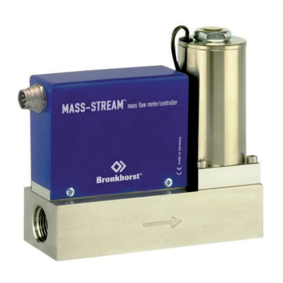
MASS-STREAM
Instruction Manual
D-6200
Analog Mass Flow Meters / Controllers
Doc. No.: 9.17.112A Date: 17-03-2017
ATTENTION
Before installing and operating the instrument it is strongly recommended
that this instruction manual should be read carefully. Not following the
guidelines could result in personal injury and/or damage to the equipment.
Advertisement
Table of Contents

Related Manuals for BRONKHORST MASS-STREAM D-6200


Summary of Contents for BRONKHORST MASS-STREAM D-6200
- Page 1 MASS-STREAM Instruction Manual D-6200 Analog Mass Flow Meters / Controllers Doc. No.: 9.17.112A Date: 17-03-2017 ATTENTION Before installing and operating the instrument it is strongly recommended that this instruction manual should be read carefully. Not following the guidelines could result in personal injury and/or damage to the equipment.
- Page 2 SCOPE OF THIS INSTRUCTION MANUAL This instruction manual of M+W Instruments GmbH covers the installation of the analog Mass-Stream instrument model series D-6200 for mass flow measurement and control of gasses and gas mixes The information in this manual has been reviewed and is believed to be wholly reliable. No responsibility, however, is assumed for inaccuracies.
- Page 3 The products of M+W Instruments GmbH are warranted against defects in material and workmanship for a period of three years from the date of shipment, provided they are used in accordance with the ordering specifications and they are not subjected to abuse or physical damage.
-
Page 4: Table Of Contents
Table of Contents ANALOG INSTRUMENTS..................5 1.1 General........................5 1.2 Installation....................... 7 1.3 Operation and Maintenance.................. 8 1.4 Specifications of analog MASS-STREAM Instruments D-6200………….…... 9 1.5 Hook-up with 6DIN Connector, 6-pin round............10 1.6 Hook-up with 15-pin sub-D connector……............10 CTA MEASUREMENT PRINCIPLE……………………………........11 The dimensional drawings and hook-up diagram of the Mass-Stream instruments... -
Page 5: Analog Instruments
ANALOG INSTRUMENTS All necessary settings for this instrument are already performed at M+W Instruments GmbH. Following the next steps carefully is the quickest way to get the instruments operational in your own system. 1.1 General The analog instruments of M+W Instruments GmbH are measurement devices for thermal mass flow and control of gasses and gas mixes. - Page 6 The declaration of decontamination is available on our accompanying CD with each instrument shipment or it can be downloaded from our website www.bronkhorst.com. Please mention the instrument’s model code and the serial number on your order, as well as your VAT number when needed.
-
Page 7: Installation
1.2 Installation To avoid personal injury and/or damage to the equipment only trained and qualified personnel shall perform the installation of the instruments: − Read the instrument’s name plate before installation and check the electrical connection, flow range, media to be measured, inlet and outlet pressure as well as input and output signals. -
Page 8: Operation And Maintenance
All instruments described in this manual carry the CE-mark. Therefore they have to comply with the EMC requirements valid for these instruments. However compliance with the EMC requirements is not possible without the use of proper cables and connector/gland assemblies. In case the instrument is connected to other devices (e.g. -
Page 9: Specifications Of Analog Mass-Stream
1.4 Specifications of analog MASS-STREAM Instruments D-6200 Measurement System Accuracy ± 3% FS including non-linearity (based on calibration with Air) (± 2% FS on request) Repeatability < ± 0.5% FS Pressure sensitivity ± 0.3% RD / bar typical (Air) Temperature sensitivity ±... -
Page 10: Hook-Up With 6Din Connector, 6-Pin Round
Hook-up with 6DIN Connector, 6-pin round See hook-up document no. 9.16.089 of the shipment’s accompanying documentation. Mass flow meter D-620: + power + output signal 0 power 0 output signal Mass flow controller D-621 / D-623: + power + output signal 0 power + setpoint signal 0 output signal... -
Page 11: Cta Measurement Principle
CTA MEASUREMENT PRINCIPLE The direct through-flow measurement with CTA (Constant Temperature Anemometry) is also named inline measurement. The working principle is based on King’s law of the ratio between the heater energy and the heat degradation by means of gas flow or liquid flows published in 1914. - Page 12 The calibration is processed with a mass flow controller which functions as a reference. The controller and the gas inlet pressure forward a defined gas flow, thus a signal of the sensor can be allocated to each specific mass flow. Each instrument is calibrated according to the customer’s operation conditions within the specified accuracy limits.
Need help?
Do you have a question about the MASS-STREAM D-6200 and is the answer not in the manual?
Questions and answers