
Related Manuals for Apera Instruments TN420


Summary of Contents for Apera Instruments TN420
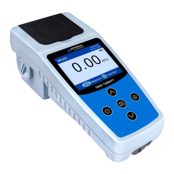
- Page 1 TN420 Portable Turbidity Meter Instruction Manual APERA INSTRUMENTS, LLC aperainst.com...
-
Page 2: Table Of Contents
Table of Contents Introduction ....................... - 1 - Technical Specifications .................... - 2 - Instrumentation Illustration ..................- 3 - Overview ......................- 3 - Configuration ...................... - 4 - Display Mode ...................... - 4 - Keypad ....................... - 5 - Power Supply ..................... -
Page 3: Introduction
INTRODUCTION Thank you for purchasing Apera Instruments TN420 Turbidity Meter (hereafter referred to as the instrument). The instrument uses tungsten filament lamp (400 – 600nm) as the light source and 90° scattering method, which is compliant with U.S EPA 180.1 method for the determination of of turbidity in drinking, ground, surface, and saline waters, domestic and industrial wastes. -
Page 4: Technical Specifications
TECHNICAL SPECIFICATIONS Measurement 90° scattering measurement Method Light Source Tungsten (400 – 600nm) filament lamp, compliant with US EPA 180.1 Method 0 to 1000 NTU (FNU), automatic range switch 0.01 to 19.99 NTU (FNU) Measuring Range 20.0 to 99.9 NTU (FNU) 100 to 1000 NTU (FNU) Accuracy ≤... -
Page 5: Instrumentation Illustration
INSTRUMENTATION ILLUSTRATION 3.1 Overview ① ② ③ ④ ⑪ ⑥ ⑤ ⑨ ⑩ ⑦ ⑧ Diagram-1 Flip cover of the sample cuvette holder Dust-proof plug (Take off the plug when ① ⑦ (Close the cover when measuring) measuring) Housing Sample cuvette holder ②... -
Page 6: Configuration
3.2 Configuration Calibration Solutions: ① 0.0, 20.0, 100, 400, 800 NTU Carrying case ② TN420 Turbidimeter ③ ⑨ Microfiber cloth ④ Power adaptor (5V 1A) ⑤ ① Silicone oil (10 ml) ⑥ ② Sample cuvettes×6 ⑦ ③ ⑧ USB Cable (under the meter) ⑧... -
Page 7: Keypad
① Calibration mode Calibration ② Standard values Menu ③ Operation guide ④ Finished calibration indicator 3.4 Keypad Diagram 3 Keypad Functions ⚫ Power on/off ⚫ In measurement mode: press to enter calibration mode ⚫ In calibration mode: press to exit calibration mode ⚫... -
Page 8: Power Supply
3.5 Power Supply The instrument adopts 3.7V rechargeable lithium battery. Fully charge the battery before first-time use. a) Charging mode · Charge via Power adaptor: connect instrument and power adaptor with a USB cable. Adaptor specification: AC110 to 240V, 50/60Hz, output: 5V/1A. ·... - Page 9 AMCO 0.0 NTU solution is provided in the default kit. For purchase details, please refer to Section 8 Replacement Parts. c) Clean cuvette surface Apply a small drop of silicone oil on the surface of the cuvette and wipe it off with a lint-free cloth to evenly distribute the silicone oil on the surface in order to cover smudges and scratches, which helps light scattering.
-
Page 10: Calibration Procedure (Take 0 Ntu And 20 Ntu As An Example)
4.2 Calibration Procedure (Take 0 NTU and 20 NTU as an example) 1) Instrument warm up (only required for low-range or high-accuracy measurement): Power on the instrument, set parameter P2 (continuous measurement time) to 5 times. Long press start continuous measurement (don't insert the cuvette), then wait for 3 to 5 minutes. 2) Open the flip cover and place the 0.0 NTU calibration cuvette. -
Page 11: Notes For Calibration
7) Press to exit calibration mode, the instrument will return to measurement mode as shown in Diagram on the right side. 4.3 Notes for Calibration a) Calibration point verification: The calibration point can be verified after the calibration is completed. If the calibration point has a large error, enter the calibration mode and repeat the calibration. -
Page 12: Turbidity Measurement
TURBIDITY MEASUREMENT 5.1 Sample Cuvette Handling 6 sample cuvettes are included in the test kit. The cap is marked with 1 to 6 , and the bottom of the cuvette also has the same number. The number of the cuvette and the cap should always be the same. -
Page 13: Notes For Measurement
Diagram 6 5.4 Notes for Measurement Keep the sample stable: After the cuvette is placed into the sample cell, it is recommended to wait for 1 to 2 minutes before calibration, as the solution will experience some shaking when the cuvette moves, which may result in inaccurate measurements. -
Page 14: Lamp Replacement
6 LAMP REPLACEMENT 6.1 Light Source Check Observe the light source on the left side of the sample cuvette holder as in Diagram 11. Turn on the instrument, and press . The light source will light up for 5 seconds. If it’s not lighting up or it’s flashing, please replace the lamp. -
Page 15: Warranty
We warrant this instrument to be free from defects in material and workmanship and agree to repair or replace free of charge, at the option of APERA INSTRUMENTS, LLC, any malfunctioned or damaged product attributable to the responsibility of APERA INSTRUMENTS, LLC for a period of TWO YEARS for the instrument from the delivery. - Page 16 APERA INSTRUMENTS, LLC Address: 6656 Busch Blvd, Columbus Ohio 43229 Tel: 1-614-285-3080 Email: info@aperainst.com Website: aperainst.com - 14 -...
Need help?
Do you have a question about the TN420 and is the answer not in the manual?
Questions and answers
Problems 1