
Related Manuals for Apera Instruments 800 Series


Summary of Contents for Apera Instruments 800 Series
- Page 1 800 Series Benchtop pH/Conductivity Meter Instruction Manual PH800 Lab pH Meter EC800 Lab Conductivity Meter PC800 Lab pH/Conductivity Meter APERA INSTRUMENTS, LLC www.aperainst.com v3.3 - 1 -...
-
Page 2: Table Of Contents
Table of Contents Brief Introduction ......................- 3 - Measuring Parameters ......................- 3 - Features and Functions ......................- 3 - Features in pH Measurement (Applicable Models: PH800, PC800) ......... - 4 - Features in Conductivity Measurement (Applicable Models: EC800, PC800) ......- 4 - What’s in the Box? ...................... -
Page 3: Brief Introduction
CR2032 3V lithium battery. BRIEF INTRODUCTI ON Thank you for purchasing 800 Series Benchtop pH/Conductivity Meters. Before using the product, please read this manual carefully to help you properly use and maintain the product. Measuring Parameters... -
Page 4: Features In Conductivity Measurement (Applicable Models: Ec800, Pc800)
time and accuracy of the measurements. Stable reading and auto lock display mode are available for choice. Meets IP54 Waterproof and dustproof rating, connectors of the meter protected by rubber cap, ensuring quality, reliability and service life especially in tough environments. Features in pH Measurement (Applicable Models: PH800, PC800) ... -
Page 5: Technical Specifications
TECHNI C AL SPECIFIC AT IONS Applicable Technical Parameters Models Measuring Range (-2.00 ~ 19.99)pH Resolution 0.1/0.01 pH Accuracy ±0.01 pH ±1 digit PH800 Temperature (0 ~ 100℃)Automatic or Manual PC800 Compensation Range Measuring Range ±1999mV Resolution Accuracy ±0.1% FS ±1 digit Conductivity: (0~200) mS/cm,including 5 ranges: (0.00~19.99)μS/cm, (20.0~199.9)μS/cm, (200~1999)μS/cm, (2.00~19.99)mS/cm,... -
Page 6: Instrument Description
INSTRUMENT DESCRIPTI ON LCD Display Figure-1 ① —— Measuring parameters ② —— Measuring value ③ —— USB data communication. The meter is connected to your PC when this icon is displayed. ④ —— Timing storage ⑤ —— Date, time, and reminder icons ⑥... - Page 7 Keypad Figure-2 Short Press — <1.5 s;Long Press — >1.5 s Table-1 Keypad Operation and Functions Keypad Operation Functions Short Press Power on/off Choose measuring mode: pH Meter: → Short Press pH/Conductivity Meter: → → Long Press Enter parameter setting Short Press ...
- Page 8 Connectors Table-2 Connectors of Different Models Connectors Model PH800 pH Meter EC800 Conductivity Meter PC800 pH/Conductivity Meter Table–3 Connector Name and Type Icon Connector Name Connector Type Reference Electrode Plug Φ2 Banana Plug pH/mV pH Electrode and ORP Electrode Plug BNC Connector TEMP Temperature Plug (sharing for pH and conductivity)
- Page 9 appear and stay before record the readings or conduct calibrations. 4.4.2 Auto-Lock Display Mode In parameter setting P5.4,select “On” to turn on the auto-lock display mode, in which the reading will be automatically locked after icon has been stably displaying for 10 seconds, and the HOLD icon will come up as shown in figure-4.
-
Page 10: Ph Measurement
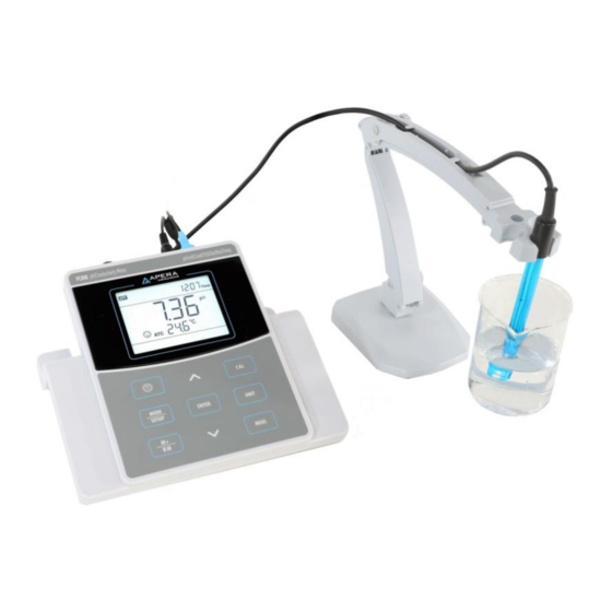
pH Measurement Preparation 5.1.1 Set up the Flexible Electrode Holder The flexible electrode holder is composed of a base and an electrode holder. Place the electrode holder right above the metal stick on the base through the hole underneath; push down; and adjust the nut on electrode holder to finish installation. -
Page 11: Information Regarding Ph Calibration
cup of distilled or deionized water, and rinse the electrode in it for a few seconds. Gently shake the probe to remove excess water, and dry it with clean tissue paper (DO NOT rub or wipe the probe, just use paper to dap off excess water). Gently stir the electrode for a few seconds after it’s dipped into the test solution and then let it stand still. - Page 12 points (see Table-5 for details). In the process of calibration, the meter will display the electrode’s slope in acid and alkaline ranges. Table-5 3-point Calibration Mode NIST Calibration icon When to adopt 1-Point 7.00 pH 6.86 pH accuracy≥ ±0.1 pH Calibration Measuring range: 7.00 pH→...
-
Page 13: Ph Calibration (Take 3-Point Calibration As An Example)
to re-calibrate. For details, please see parameter setting P1.3 (Section 7.3) 5.3.6 pH Isothermal Measurement Principle According to the pH isothermal measurement principle, the closer the test sample’s temperature is to the calibration solution’s, the higher the accuracy of the measurement. This principle is recommended to follow when conducting tests for the best result. -
Page 14: Sample Measurement
5.4.5 Take out pH electrode, rinse it in distilled water, dry it, and dip it into pH 10.01 buffer solution. Stir the solution gently and let it stand still in the buffer solution until a stable reading is reached. The meter’s display will show recognition process of calibration buffer solution at the bottom right of LCD. -
Page 15: Maintenance Of The Ph Electrode
Press when reading is not stable during Press key when icon appears and calibration. stays. 1. Check whether there are bubbles in glass bulb. During calibration, readings being unstable for over 3 minutes 2. The pH Electrode is aged. Replace a new one. -
Page 16: Mv Measurement
should be refreshed often, especially after heavy use. We recommend 10-15 times of use before replacing the pH buffers. 5.6.3 Protect the glass bulb sensor The sensitive glass bulb at the front of the combination electrode should not come in contact with hard surfaces. -
Page 17: Notes On Orp Measurement
Notes on ORP measurement 6.2.1 ORP measurement does not require calibration. When the user is not sure about ORP electrode quality or measuring value, use ORP standard solution to test mV value and see whether ORP electrode or meter works properly. Table-8 is the data of standard ORP solution for 222 mV. Table-8 ORP Standard Buffer Solution(222mV±15mV,25 )... -
Page 18: Information Regarding Conductivity Calibration
Table–9 Electrode constant and measuring range <20 μS/cm 1.0 μS/cm to 100 mS/cm >100mS/cm Range Conductivity K=0.1 K=1.0 K=10 electrode constant Standard 84μS/cm 84μS/cm 1413 μS/cm 12.88 mS/cm 111.8 mS/cm solution DJST-0.1-F Electrode’s 2310T-F conductivity conductivity 2301T-F conductivity electrode electrode model electrode Note: When testing ultra-distilled water with conductivity less than 1.0 μS/cm, a flow test should be... - Page 19 7.3.3 Single point and multi-point calibration If 1-point calibration is conducted after 3-point or 4-point calibration being done, the previous calibration values in the same range will be replaced. In the meanwhile, the meter will display the 1-point calibration’s icon, and the other calibration icons will be removed, but the chip will still store the data from the last calibration.
-
Page 20: Conductivity Calibration (Take 1413 Μs/Cm As An Example)
the LCD (as showed in Figure-11). At the time, the meter can still be operated. It is just reminding you to do calibration in order to ensure the accuracy. After calibration, the Er6 icon will disappear; To make it disappear, users can also choose “No” in P2.2 in parameter setting. 7.3.8 Check calibration date In this mode, users can see the date and time of last calibration to help determine if there is a need... -
Page 21: Sample Test
testing and experience. Table – 12 lists some commonly used Conductivity and TDS conversion factors. This is for your reference only. Table–12 Conductivity and TDS conversion factors Conductivity of solution TDS conversion factor 0~100 μS/cm 0.60 100~1000 μS/cm 0.71 1~10 mS/cm 0.81 10~100 mS/cm 0.94... -
Page 22: Maintenance Of The Conductivity Electrode
all calibration data is deleted and the meter restores to the theory value. Some functions restore to the original value (refer to appendix -1). When calibration or measurement fails, please restore the meter to factory default setting and then perform re-calibration or measurement. Please note once set the factory default, all the data deleted will be irretrievable. - Page 23 to change submenu: P2.1→P2.2→ … →P2.7. See 7.4 for details. 7.2.3 In P5.0, press to enter the submenu P5.1 for basic parameter setting, press to change submenu: P5.1→P5.2→…→P5.6. See 7.5 for details. Figure-14 Main Menu pH Setting Submenu P1.1 Select pH buffers P1.2 Set up calibration reminder P1.3 Check calibration date P1.4 Restore to factory default...
- Page 24 P1.2 — Set up calibration reminder (No—H00—D00) 1. Press , ”No” flashes, press to choose No→H00→D00; NO—no setting; H00—set hours(0~99); D00—set days(0~99). 2. When “H” flashes, press , “00” flashes, press to adjust hours, press to confirm; When “D” flashes, press ,“00”flashes, press to adjust days, press to confirm;...
- Page 25 P2.4 —Select reference temperature (15.0 —30.0 ) 1. Press , “25.0℃” flashes, press to adjust temp. from 15℃ to 30℃; press to confirm. 2. Press to enter P2.5, or press to return to measurement mode. P2.5 —Adjust temp. compensation coefficient (0.00-9.99%) 1.
- Page 26 P5.3 — Clear storage (No—Yes) 1. Press , “No” flashes, press to choose No→Yes; press confirm. No— not to clear data storage; Yes—clear all data storage 2. Press to enter P5.4, or press to return to measurement mode. P5.4 — Set up Auto-Lock reading mode (Off—On) 1.
-
Page 27: Usb Data Communication
USB D ATA COMMUNIC ATI ON The instrument uses PC-Link software for data communication through USB connector and cable. Software Interface Figure- 15 ① — Stored data (a)Press “Download” Key to upload the data in the meter to the software, including date, time, measurements, temperature, and temperature compensation mode. - Page 28 Clear — Click it to clear all the data. Export — Click it to export all the data to a Microsoft Excel file. Exit — Click it to exit the program. Install software The PC-Link software works for all Windows based system (does not work for Mac). Insert the PC- Link disk into the computer, open the PC-Link folder where you will find the folder for PC-Link software and a zipped file for drivers.
-
Page 29: Recommended Ph Electrodes For Specific Applications
We warrant this instrument to be free from defects in material and workmanship and agree to repair or replace free of charge, at option of APERA INSTRUMENTS, LLC, any malfunctioned or damaged product attributable to responsibility of APERA INSTRUMENTS, LLC for a period of THREE YEARS (SIX MONTHS for the probe) from the delivery. -
Page 30: Appendix 1: Table Of Parameter Setting And Factory Default Setting
12 APPENDIX 1: TABLE OF PAR AM ETER SETTI NG AND FACTORY DEFAULT SETTI NG Factory Mode Symbol Parameter Abbreviation Content Default P1.1 Select Buffer Series USA-NIST - P1.2 Set calibration reminder No-H00-D00 P1.0 P1.3 - - Check calibration date and time P1.4 Restore factory default No-Yes... -
Page 31: Appendix 2: Icons And Abbreviation
13 APPENDIX 2: ICO NS AN D ABBREVI ATI ON Mode Symbol Abbreviation Meaning P1.1 Standard buffers P1.2 Due Calibration P1.0 P1.3 P1.4 Factory default setting P2.1 Cell P2.2 Due Calibration P2.3 P2.0 P2.4 Reference temperature Conductivity Temperature compensation P2.5 coefficient P2.6 TDS coefficient... -
Page 32: Appendix 3: Table Of Self-Diagnosis Symbol
60mV or >60mV) pH electrode slope out of range (<85% or >110%) √ √ Enter in pre-set due calibration to remind re-calibration √ APERA INSTRUMENTS, LLC Address: 6656 Busch Blvd, Columbus Ohio 43229 Tel: 1-614-285-3080 Email: info@aperainst.com Website: www.aperainst.com - 32 -...
Need help?
Do you have a question about the 800 Series and is the answer not in the manual?
Questions and answers