Table of Contents
Advertisement
Quick Links
Advertisement
Table of Contents

Related Manuals for COBHAM EXPLORER 8100 Ku


Summary of Contents for COBHAM EXPLORER 8100 Ku
- Page 1 EXPLORER 8100 Ku Conversion Kit Hardware installation guide...
- Page 3 Manuals issued by Thrane & Thrane A/S are periodically revised and updated. Anyone relying on this information should acquire the most current version e.g. from www.cobham.com/satcom, Cobham SYNC Partner Portal, or from the distributor.
-
Page 4: Table Of Contents
Table of contents Chapter 1 Conversion to Ku-band To unpack ........................... 1 1.1.1 What’s in the box ........................1 1.1.2 Initial inspection ........................1 Prerequisites ..........................2 1.2.1 Software version ........................2 1.2.2 Tools needed ..........................2 To modify the Antenna ....................3 1.3.1 To prepare the Ka (eTRIA) antenna ................ -
Page 5: Conversion To Ku-Band
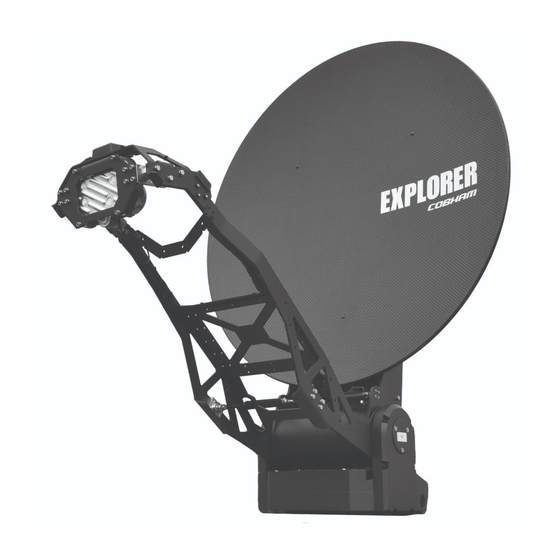
Conversion to Ku-band This guide describes the hardware installation when converting an EXPLORER 8100 Ka (eTRIA) antenna (408147B) to an EXPLORER 8100 Ku antenna, and the minimum initial configuration necessary. Once you have converted the hardware, refer to the EXPLORER 8000 User and Note installation manual (98-145510) for setup and configuration. -
Page 6: Prerequisites
Before conversion, update the ACU software to minimum version 1.58. 1.2.2 Tools needed The following tools are needed to convert an EXPLORER 8100 Ka (eTRIA) antenna to an EXPLORER 8100 Ku antenna: • Allen (hex) key set • Torx screwdriver set • Adjustable wrench •... -
Page 7: To Modify The Antenna
To modify the Antenna To modify the Antenna The Ku conversion procedure of the antenna consists of the following operations: • To prepare the Ka (eTRIA) antenna • To remove the eTRIA • To connect and arrange the cables • To install the BUC •... - Page 8 To modify the Antenna 2. Insert the hex L key at the top of the L-shaped hole, tip it downwards and follow the direction of the hole to the left to release the lock. Leave the hex L key in the Released position while adjusting the Important elevation.
-
Page 9: To Remove The Etria
To modify the Antenna 1.3.2 To remove the eTRIA 1. Carefully cut the tape protecting the connector and adapter (if present) at the eTRIA and remove the tape. 2. Cut the strip holding the cable on the eTRIA. Remove tape Cut cable strip Figure 5: Remove cable strip and tape at SMA connector for eTRIA 3. -
Page 10: To Connect And Arrange The Cables
To modify the Antenna 1.3.3 To connect and arrange the cables For ease of access to cables and connectors, start by removing the reflector. Do as follows: 1. Unscrew the screws for the reflector while supporting the reflector. Figure 7: Take off reflector 2. - Page 11 To modify the Antenna 5. Fit the Tx cable behind the reflector and connect the angled connector of the cable to the N-connector on the antenna. See Figure 10. 6. Take the cable harness and connect the GTC C4 connector behind the reflector. GTC C4 connector N-connector...
- Page 12 To modify the Antenna 9. Loosely attach the cables including the protective sleeve to the Feed arm with cable strips. Allow space for a final adjustment of the cables. Cable strip Cable strip Figure 13: Attach cables and protective sleeve 10.Arrange the cables and work your way along the Feed arm while cutting the remaining cable strips and placing new strips loosely around all the cables.
-
Page 13: To Install The Buc
To modify the Antenna 1.3.4 To install the BUC 1. Mount the BUC brackets loosely with the included screws (2 screws each, if you are using the brackets for the 8 W BUC). Place the bracket with the Waveguide interface (square hole) closest to the free end of the Feed arm. - Page 14 To modify the Antenna 5. While supporting the BUC, remove the supporting screws at the front of the BUC and fit the two gaskets between bracket/BUC and Waveguide/bracket. Figure 18: Waveguide, gaskets 6. Mount the 4 screws and tighten them to torque 2.5 Nm. Figure 19: Waveguide, mount screws 7.
-
Page 15: To Install The Ku Rf Assembly
To modify the Antenna 1.3.5 To install the Ku RF assembly 1. Carefully place the Ku RF assembly over the 2 steering pins (with the LNB pointing away from the antenna pedestal) and mount the 4 screws (2 Hex screws and 2 Torx screws). Hex screw Steering pin Torx screw... - Page 16 To modify the Antenna 3. Adjust the SMA connector so that the cable exits to the right (after tightening) when the OMT and LNB are in upright position. Tighten the connector to torque 1.7 Nm. Figure 24: SMA connector on LNB 4.
- Page 17 To modify the Antenna 6. Continue to place strips at regular distances to hold the 2 cables together up to the Feed arm. Figure 27: Cable strips on LNB and OMT cables 7. Turn the OMT as far as possible in both directions in order to make sure the cable length is sufficient.
- Page 18 To modify the Antenna 9. Tighten all the strips along the Feed arm, starting at the Polarization unit, while adjusting and arranging the cables along the way. Figure 29: Cable strip on Feed arm 10.Arrange any excess cable length behind the reflector. 11.Cut off excess material from all the cable strips.
-
Page 19: Final Assembly
Note that you must also enter the pol axis zero value, which is found on the type label on the Polarization unit (called “Cal. value” on the type label). Figure 32: Cal. value on type label for EXPLORER 8100 Ku Conversion Kit Do as follows: 1. -
Page 20: Create And Activate A Satellite Profile
To update the configuration to Ku 2. Start a telnet session as described in the appendix “Command line interface” in the User & installation manual. 3. Log in (default user name: admin, default password: 1234). 4. Enter the command: antenna_data type Ku <pol_zero> (where <pol_zero>... - Page 22 98-155944-A www.cobham.com/satcom...
Need help?
Do you have a question about the EXPLORER 8100 Ku and is the answer not in the manual?
Questions and answers