Advertisement
Table of Contents
- 1 Intended Audience
- 2 Initial Use
- 3 Revision History
- 4 Product Information
- 5 External Ports
- 6 General Specifications
- 7 Input Specifications
- 8 Output Specifications
- 9 Terminal Layout
- 10 Wiring Precautions
- 11 Communication Connection
- 12 RS485 Serial Connection
- 13 Operation and Maintenance
- 14 Warranty Agreement
- 15 Product Warranty Card
- Download this manual
Advertisement
Table of Contents

Related Manuals for Inovance H5U Series


Summary of Contents for Inovance H5U Series
- Page 1 H5U Series Programmable Logic Controller User Guide Suzhou Inovance Technology Co., Ltd. Suzhou Inovance Technology Co., Ltd. Address: No.16 Youxiang Road, Yuexi, Wuzhong District, Suzhou, P.R.China 215104 *19011517A01* Service line: 4000-300124 19011517A01 http://www.inovance.com...
-
Page 2: Intended Audience
3. The "CAUTION", "WARNING", and "DANGER" signs are only supplements to the safety precautions. 4. Use this equipment based on the designated environment requirements. Damage caused by improper usage is not covered by warranty. 5. Inovance shall take no responsibility for any personal injury or property damage caused by improper usage. - Page 3 ■ Safety Levels and Definitions Indicates that failure to comply with the notice may result in severe personal DANGER injury or even death. Indicates that failure to comply with the notice may result in severe personal WARNING injury or even death. : Indicates that failure to comply with the notice may result in minor or moderate CAUTION personal injury or damage to the equipment.
- Page 4 Installation WARNING ◆ The equipment must only be used indoor. Ensure that the environment meets the requirements in the following "General Specifications" section. ◆ Keep the equipment away from strong magnetic fields, direct sunlight, high temperature, flammable gases, steam, and dust. Failure to comply may result in damage. ◆...
- Page 5 CAUTION ◆ Cut off the main power supply before connecting the power supply of the equipment. Failure to comply may result in electric shock. ◆ The input power of the equipment is DC 24V. Therefore, check regularly that the DC power provided by the switching-mode power supply unit is stable.
-
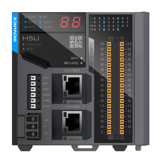
Page 6: Product Information
Transistor output blank 32 axes Figure 1 Model and nameplate Model Category Description Code H5U series PLC with 16 inputs and 14 outputs H5U-1614MTD 01440087 (32-axis) H5U series PLC with 16 inputs and 14 outputs H5U-1614MTD-A16 01440235 (16-axis) H5U series PLC with 16 inputs and 14 outputs... - Page 7 Port Port Type Definition Description Identifier ON when the system is running; Current operation status OFF when the system is shut of the system down. PLC system error – Operation Battery error – status indicator EtherCAT bus error – CRUN CAN running –...
-
Page 8: General Specifications
Port Port Type Definition Description Identifier See the terminal layout 11 I/O terminal – 16 inputs and 14 outputs description for details. For connecting an 16 I/O expansion modules are Module – expansion module or allowed at most without support expansion port device for hot-swapping. -
Page 9: Input Specifications
Item Specifications IP rating IP20 Net Weight 0.46kg Altitude 2000m Pollution degree Overvoltage 1.4 Input Specifications Input signals can be bipolar voltages. The signal status is OFF when the absolute voltage value is less than 5.0 V; ON when the absolute voltage value is more than 15.0 V;... -
Page 10: Output Specifications
1.5 Output Specifications The output ports use dry contact output, which is closed in the ON state and open in the OFF state. High-speed Output Port General Output Port Item (Y0–Y7) (Y10–Y15) Signal circuit supply voltage 5–24 V DC Output type Transistor NPN output Circuit insulation Optocoupler insulation... -
Page 11: Terminal Layout
2 Mechanical Design Reference ■ Exterior and Dimensions 83.0 95.0 90.0 Figure 3 Exterior and dimensions (mm) of the PLC 3 Electrical Design Reference Terminal Layout Figure 4 Terminal layout of the PLC... -
Page 12: Wiring Precautions
Definition Terminal Terminal Definition General input General input General input General input General input General input General input General input High-speed input Medium-speed input High-speed input Medium-speed input High-speed input Medium-speed Input High-speed input Medium-speed input High-speed input common General and high-speed input terminal common terminal General output... - Page 13 3.2 Equivalent Circuits with General and High-speed Inputs ■ Wiring for Sinking and Sourcing Inputs User signal cable User signal cable Equivalent circuit inside Equivalent circuit inside the PLC's master module the PLC's master module Sensor Sensor Wiring for sink input Wiring for source input 3.3 Equivalent Circuits with General and High-speed Output Transistors...
-
Page 14: Communication Connection
4 Communication Connection 4.1 Cable Selection and Preparation Wire Supporting Cable Diameter Terminal Cable Cable Type Material Material Torque Temperature Power cable Tubular lug 0.5–1.5 24–16 5 in-lbs 75℃ Signal cable Tubular lug 0.5–1.5 24–16 75℃ French version: Diamètre du Matériel Matériau Couple... - Page 15 Figure 5 Communication ports of the PLC The port pins are defined as follows. Signal Description 485+ RS485 differential pair positive signal of COM0 485- RS485 differential pair negative signal of COM0 Power ground of COM0 CANH CAN Rx CANL CAN Tx CGND CAN ground end...
- Page 16 4.3 EtherCAT Bus Connection 1) EtherCAT Specifications Item Specifications Communication protocol EtherCAT protocol Service supported CoE (PDO and SDO) Synchronization mode Distributed clock (DC) used by the servo, with synchronized I/O Physical layer 100BASE-TX Baud rate 100 Mbit/s (100Base-TX) Duplex mode Full duplex Topology Linear topology...
- Page 17 ● Length requirements: FastEthernet has proved that the cable length between devices should not exceed 100 m in the case of an EtherCAT bus. A longer cable will result in signal attenuation that affects communication. ● Technical requirements: Continuity testing is conducted on a 100% basis and no short circuits, open circuits, and poor contact are found.
- Page 18 Add a 120 Ω CAN bus termination resistor at both ends of the bus. You can use a DIP switch to choose whether to activate the H5U series built-in resistor. The following figure shows the CAN bus connection topology.
-
Page 19: Rs485 Serial Connection
4.6 RS485 Serial Connection The following figure shows the RS485 bus connection topology. It is recommended that the RS485 bus be shielded twisted pairs, with the 485+ and 485- terminals connected by the twisted pairs. Connect a 120 Ω termination resistor to each end of the bus to prevent signal reflection. - Page 20 4.7 Ethernet-based Monitor Connection Network diagram The PLC's Ethernet port can be connected to a hub or switch by an Ethernet cable and then to other network equipment for multi-point connection. Ethernet cable Figure 10 PLC connecting to other equipment through a switch The PLC can also be connected to a PC or an HMI by an Ethernet cable in point-to- point mode.
-
Page 21: Operation And Maintenance
5 Operation and Maintenance 5.1 Start and Shutdown After writing a program to the PLC, take the following steps to start or shut down the PLC. After writing a program to the PLC in the STOP state, start the system as follows: Set to RUN 1. - Page 22 5.3 PLC Indicators Indicator Description Indicator Description Current operation status (RUN or STOP) of the system EtherCAT bus RUN indicator BF indicator ON when the system is running; error OFF when the system is shut down. ERR indicator System error CRUN indicator CAN running BAT indicator Battery error...
- Page 23 After the IP menu function starts to run, the LED starts a countdown from 10. The IP address is restored when the countdown reaches 0 and the new IP address will be applied. To cancel restoration, press the MFK button before the countdown reaches 0.
-
Page 24: Warranty Agreement
During the warranty period, if the product fails or is damaged under normal use in compliance with the instructions, Inovance is responsible for free repair. Within the warranty period, repair will be charged for damages due to the following causes:...
Need help?
Do you have a question about the H5U Series and is the answer not in the manual?
Questions and answers