Table of Contents
Advertisement
Quick Links
H0U Series PLC User Manual
Thank you for purchasing the H0U series programmable logic controller (PLC) independently developed by
Inovance Control Technology Co., Ltd. Read the manual carefully to be familiar with the product features
and be able to use the product safely.
This manual describes the specification, features and usage of the H0U series PLC. For the developing
environment and design method of user programs, see the H0U Series PLC Programming Manual and the
H1U/H2U Series PLC Instruction & Programming Manual issued by Inovance.
The H0U series PLC has the following features:
◆ It integrates PLC and TOD programs and allows programming of control logics & display interface.
◆ It supports all the instructions of the H1U and the CAN communication protocol.
◆ It reaches the user memory space of 8k steps and the maximum capacity of the user TOD programs of
56 KB.
◆ It has two independent communication ports (COM1, COM2), making it act as master or slave.
◆ It supports 6-channel high-speed inputs and 2-channel high-speed outputs (only transistor output).
◆ It supports display in both simplified Chinese and English, and switchover between the two languages
online.
◆ It has a total of 25 functional keys, whose functions can be defined freely.
◆ It allows you to download the PLC and TOD programs via AutoShop and HTodEditor.
Safety Information and Precautions
In Design
■
DANGER
◆ Provide a safety circuit outside the PLC in the application so that the control system can still work safely
even if external power failure or PLC fault occurs. Take the following aspects into considerations in the
design:
◆ In the external circuit of the PLC, an emergency stop circuit, a protection circuit, an interlock circuit
of forward/reverse rotation operation, and position upper/lower limit interlock circuit are necessary to
prevent equipment damage
◆ To ensure safe running of the equipment, external protection circuit and safety mechanism must be
designed for the output signals that may cause serious accidents.
◆ When the CPU of the PLC detects an abnormality of its own system, all outputs may be cut off. When
a failure occurs on the controller circuit, related outputs may be out of control. Thus, an appropriate
external circuit must be designed to ensure normal running of the equipment.
◆ When the output units such as relay or transistor are damaged, related outputs will be out of control
and be continuously kept ON or OFF. Return the AC drive with damaged output unit to Inovance for
repair.
◆ The PLC is designed for indoor electric environment. A lightning protection device must be installed for
the power supply system, so that lightening overvoltage is not applied on terminals of the PLC, avoiding
damage to the equipment.
During Installation
■
WARNING
◆ Install the PLC in places free from dust, oil smoke, conducting dust, corrosive gas, combustible gas,
high temperature, condensation, wind & rain, vibration and shock. In addition, electric shock, fire,
malfunction may also cause damage and deterioration to the equipment.
◆ During screw hole processing and wiring, ensure that no metal filing and cable end falls into the
ventilation hole of the controller, because such stuff may causes a fire, fault, or malfunction.
◆ After installation of the newly purchased PLC is complete, ensure that there is no foreign stuff on the
surface of ventilation. Failure to comply may result in poor cooling effect during running, which may
lead to a fire, fault or malfunction.
◆ The installation and wiring must be secure and reliable. Poor contact may cause malfunction.
1
At Wiring
■
DANGER
◆ Ensure that all power supplies are cut off before installation or wiring.
◆ During screw hole processing and wiring, ensure that no metal filings or cable end drops into ventilation
holes of the controller. Failure to comply may result in a fire, fault or malfunction.
◆ Perform wiring or plug/remove the cable connector only after power-off. Failure to comply may result in
electric shock or damage to the circuit.
WARNING
◆ Don't provide external power supply to terminal 24+ of the main unit or expansion unit.
◆ Use shielded cables for high-frequency signal input/output in applications with severe interference to
enhance anti-interference capacity of the system.
During Running and Maintenance
■
DANGER
◆ Connection or removal of the communication cable, cables of the extension card and cables of the
control unit can be performed only after power-off. Failure to comply may result in damage to the
equipment or malfunction.
◆ The operations such as online modification, forcible output, RUN and STOP can be performed only
after you read the manual and guarantee safety.
WARNING
◆ Treat scrapped PLC as ordinary industrial waste.
Product Information
Designation Rules
■
H
- 0808 MRT - XP
0U
1
2
3
4
5
6
1: Product information
H: Inovance controller
2: Series No.
0U: TOD+PLC integrated controller
3: Input points
08: 8 inputs
4: Output points
08: 8outputs
5: Module classification
M: Main module of general-purpose controller
6: Output type
R: Relay, T: Transistor
7: Output type
Mixed output
8: Reserved for future expansion
9: CPU type
XP: NXP-type CPU
10: Special function
6AT (standard): built-in analog extension card;
6ATC (customized): built-in analog extension card and CAN card; CAN (customized): built-in CAN card
Basic Parameters
■
The following table describes the basic parameters of the H0U series PLC.
I/O Features
Total
PLC Model
Total
High-Speed
Total
I/Os
Inputs
Inputs
Outputs
H0U-0808MR-XP
2 x 60 kHz
16
8
8
4 x 10 kHz
H0U-0808MRT-XP
H0U-1616MR-XP
2 x 60 kHz
32
16
16
4 x 10 kHz
H0U-1616MRT-XP
H0U-0808MR-XP-
6AT
2 x 60 kHz
16
8
8
4 x 10 kHz
H0U-0808MRT-XP-
6AT
H0U-1616MR-XP-
6AT
2 x 60 kHz
32
16
16
4 x 10 kHz
H0U-1616MRT-XP-
6AT
2
Total frequencies of high-speed inputs do not exceed 70 kHz.
The following table describes the functions of the built-in extension cards.
Extension
Card
Model
6AT
6ATC
CAN
General Specifications
■
The following table describes the general specifications of the H0U series PLC.
Type
Ambient
- 6AT
temperature
7
8
9
10
Humidity
Air pressure
Sine
vibration
Random
vibration
Shock
Dip
Built-in
The following figure shows the installation dimensions of the H0U series PLC.
Communication
Analog
High-Speed
Output
interface
Card
Outputs
Type
-
Relay
2 x 100 kHz Transistor
2 x RS485
-
1 x USB
-
Relay
2 x 100 kHz Transistor
-
Relay
2 x 100 kHz Transistor
2 x RS485
6AT
1 x USB
-
Relay
2 x 100 kHz Transistor
Note
Analog Input
Analog Output
Temperature Detection
Voltage: -10 to +10 V
A total of three terminals
Voltage: -10 to +10 V
Current: 4–20 mA
are available, supporting
Current: 4–20 mA
Current: 0–20 mA
2-channel temperature
Current: -20 to +20 mA
They are switched
detection and also PT100
They are switched over
over via soft
and TC detection, which are
via soft component.
component.
switched over via software.
Voltage: -10 to +10 V
A total of three terminals
Voltage: -10 to +10 V
Current: 4–20 mA
are available, supporting
Current: 4–20 mA
Current: 0–20 mA
2-channel temperature
Current: -20 to +20 mA
They are switched
detection and also PT100
They are switched over
over via soft
and TC detection, which are
via soft component.
component.
switched over via software.
-
-
-
Environment Parameters
Transportation
Use Condition
Parameter
Unit
Low temperature
°C
-5
High temperature
°C
55
95
Relative humidity
%
(30°C ± 2°C)
(40°C ± 2°C)
Low pressure
kPa
70
High pressure
kPa
106
Shift
mm
3.5 (5–9 Hz)
Acceleration
m/s2
10 (9–150 Hz)
Acceleration
m2/s3
5–20 Hz: 1.92 dB
-
spectral density
(dB/Oct)
20–200 Hz: -3 dB
Frequency range
Hz
-
Vibration direction
-
-
Type
-
-
Acceleration
m/s2
-
Dip height
m
-
Mechanical Design
200 mm
Fixed
146 mm
bolt hole
Front view
3
CAN
Communication
-
One CAN
communication port
supporting CANlink
protocol
One CAN
communication port
supporting CANlink
protocol
Storage
Condition
Condition
-40
-40
70
70
95
-
70
70
106
106
-
-
-
-
-
5–200
-
X/Y/Z
-
Half-sine
-
180
-
1
-
42 mm
Side view
Advertisement
Table of Contents

Related Manuals for Inovance H0U Series


Summary of Contents for Inovance H0U Series
- Page 1 The following figure shows the installation dimensions of the H0U series PLC. Total Communication PLC Model Analog Total High-Speed Total High-Speed Output and be continuously kept ON or OFF. Return the AC drive with damaged output unit to Inovance for I/Os interface Card 42 mm Inputs Inputs Outputs Outputs Type 200 mm repair.
- Page 2 ON response time 20 ms (max.) The H0U series PLC has four communication ports as standard configuration. COM0, COM1 and High-speed outputs: 10 us COM2 are standard RS485 communication interfaces. COM0 is used for user program downloading, Others: 0.5 ms commissioning and monitoring.
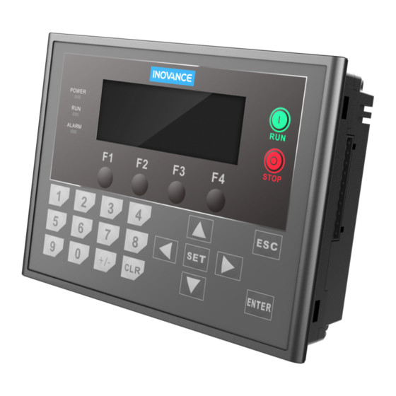
- Page 3 The use of soft components of the H0U series PLC is the same as that of the H1U series PLC. 1. Key setting The operation panel consists of 25 keys. The functions of the keys are the same as those of the HMI.
Need help?
Do you have a question about the H0U Series and is the answer not in the manual?
Questions and answers