Table of Contents
Advertisement
Advertisement
Table of Contents

Related Manuals for Inovance NICE1000


Summary of Contents for Inovance NICE1000
- Page 1 NICE1000 Elevator Integrated Controller Setup Manual –Brief Version 1.4...
-
Page 2: Table Of Contents
Sr. No Subject Page Safety Information and Precautions -------------------------------------------------------- NICE1000 Product Details -------------------------------------------------------------------------- NICE 1000 Product Information -------------------------------------------------------------------- Dynamic Brake Resistor (DBR) for NICE 1000 -------------------------------------------------- Electrical Wiring of NICE 1000 --------------------------------------------------------------------- 2.3.1 Power Terminal Connection and Terminal Function -------------------------------------- 2.3.2 MCTC-MCB-A main control panel wiring instruction -----------------------------------... -
Page 3: Safety Information And Precautions
1. Safety Information and Precautions In this manual, the notices are graded based on the degree of danger: DANGER indicates that failure to comply with the notice will result in severe personal injury or even death. WARNING indicates that failure to comply with the notice will result in potential risk of severe personal injury or even death. - Page 4 Do not loosen the fixed screws of the components, especially the WARNING screws with red mark. Do not install the controller on vibrating parts. Failure to comply may result in damage to the equipment or unexpected accidents Handle the equipment with care during transportation to prevent damage to the equipment.
- Page 5 the moment. Failure to comply may result in electric shock. Do not touch the fan or the discharging resistor to check the temperature. Failure to comply will result in personal burnt. Signal detection must be performed only by qualified personnel during operation.
- Page 6 equipment periodically. Only timely troubleshooting can ensure the safety of passengers. CAUTION The packaging materials, screws and terminal blocks can be re-used and it is suggested that you keep them well for future use. Disposal The electrolytic capacitors on the main circuits and PCB may explode WARNING when they are burnt.
- Page 7 (50 Hz). 1.3 Protective Functions Adopting different protective functions for different levels of faults, the NICE1000 provides the elevator running system with full abnormality protection. For detailed solutions to the faults, Faults of the controller are classified as follows: 1.
-
Page 8: Nice1000 Product Details
Dis with the stored floor data. If the deviation is large, the system reports an alarm. Note:- This commissioning setup manual is to be referred along with the NICE1000 Electrical Drawing and User Manual. 2. NICE1000 Product Details: ... -
Page 9: Nice 1000 Product Information
NICE 1000 Product Information: Name Designation Rules & Nameplate: Applies to both Asynchronous/Synchronous Motor. Name Designation Rules: For example, NICE – L – G – 40 11 Applicable motor power NICE series Integrated Controller 3-phase 440V Only applied to Lift Structure number Structure number ‘G’... -
Page 10: Dynamic Brake Resistor (Dbr) For Nice 1000
OUTPUT 3PH AC380V 13A 0~90HZ Suzhou MONARCH Control Technology Co., Ltd., 2.2 Dynamic Brake Resistor (DBR) for NICE 1000: External DBR is to be connected between PB and + terminals in NICE1000 System Model Average Power of the Maximum Resistance... -
Page 11: Electrical Wiring Of Nice 1000
2.3 Electrical Wiring of NICE 1000 Electrical wiring includes Power terminal, DBR, Main Control Board wirings, Extend board (If present) and PG card (for Feedback device, Encoder) wirings 2.3.1 Power Terminal Connection and Terminal Function: a) Power Circuit: b) Terminal Function: Terminal Name Description... -
Page 12: Mctc-Mcb-A Main Control Panel Wiring Instruction
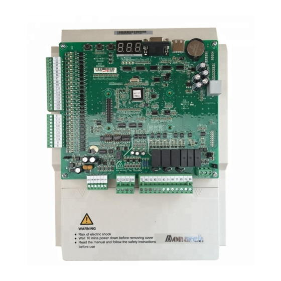
2.3.2 MCTC-MCB-A main control panel wiring instruction Main Control Board Details: S1 Button for (L1-L20 Call Shaft Learning Button Function) L1~L20 X1~X24 Input LED indicator LED indicators ER, OK, MOD LED indicator CN10, CN11 (X1~X24 Input (LED Keypad) Terminals) J11 (Expansion/PG card) Y0~Y22 Output J5, J6, J8 (Jumpers) - Page 13 Terminal functions of NICE 1000’s Main Control Board (MCB) Page 12 of 49 Version : 1.4 Date of issue : 03-07-14...
- Page 14 Indicator light instruction of MCB: Terminal Name Instruction Error Indicator When error occurs, ER indicator LED lit (Red) OK indicator When system ok, OK indicator Lit (Green) MODBUS communication When expansion board MODBUS communication indicator is good, indicator lit (Green) When corresponding external input is given, the X1~X27 Input signal indicator...
-
Page 15: Mctc-Kz-B Expansion Board Details
2.3.3 MCTC-KZ-B Expansion Board Details: The Expansion Board mainly is used for floor input call button expansion, relay out expansion, analogue weighing expansion and MODBUS communication expansion. a) Appearance of Expansion board The Expansion board is placed on the connector J11 of Main Control Board (MCB) b) Connector CN12 and CN13, indicator and Jumper details of Expansion board Terminal Name... - Page 16 Connector CN2 in MCTC-MCB-A of NICE1000 2. Encoder Type Sin/Cos encoder wiring details Page 15 of 49 Version : 1.4 Date of issue : 03-07-14...
- Page 17 2.2 Encoder Pin connections for ECN 413/1313 with MCTC-PG-F1 card ‘D’ Type Pin Solder side 15Pin Connector Red/Black Synchronous Machine Green/Black Yellow/Black White/Green White ECN413 Blue/Black /1313 Brown/Green CLK+ Violet CLK- Yellow DATA+ Grey DATA- Pink Page 16 of 49 Version : 1.4 Date of issue...
-
Page 18: Operating Led Keypad For Nice 1000 System
3. Operating LED keypad for NICE 1000 system:- LED Function Indicators Unit Indicators 5 Digit ‘7 Segment’ : Frequency display : Current : Voltage : Speed : Percentage ENTER Key Program Key SHIFT Key Quick Key Run Key STOP/RESET Key Up Key Multifunction Key Down Key... -
Page 19: Viewing And Operation Instruction Of Function Code Using Operating Keypad
3.1 Viewing and operation instruction of Function Code using operating Keypad:- NICE 1000 adopt three level menu to conduct the parameter setting. Three level menu include: Function Parameter Group (First Level) Function Code (Second Level) Function Code Setting (Third Level) Operation procedures are as follows Example: Change function code F0-06 from 50.00Hz to 15.00Hz Display... -
Page 20: Identify The Nice 1000 Control Panel Components
4. Identify the NICE 1000 control Panel components: NICE 1000 series Breakers & PFR Contactors SMPS & Relays EIS/ERO Transformer & Choke Control Terminals Power Terminals 4.1 Switch off all the control panel breakers to avoid an unexpected controller power up 4.2 Select the ‘Controller INS ’... - Page 21 4.3 Control Panel and Field Wiring verification: 4.3.1 Check all Field Wiring (Machine Room, Controller, Hoist-way, Car top, COP and LOP) are connected as per the given Electrical Drawing 4.3.2 Check controller wiring and field wiring for loose connection. 4.3.3 Check control panel wiring for short circuit using Multi meter (Field and control panel wiring) FROM EARTH SOURCE (OR)
-
Page 22: Initial Start Up Procedure
5. Initial Start Up procedure: 5.1 Verification of different voltage level sources:- 5.1.1 Before Control Panel Power Up, Disconnect all the Control Terminal wiring which are connected to MCTC-MCB-G of NICE 1000 5.1.2 Switch on the main power supply Circuit Breaker; check the incoming voltage level between R vs S, S vs T, T vs R and R S T with respect to N at Lift Control Panel using Multi meter MULTIMETER 5.1.3 Make sure that the Incoming Voltage level satisfies the specification... - Page 23 5.1.5 Verify that the following voltage levels are OK and within the limit 240VAC Level ± 24VDC Level 110VAC Level ± 110VDC Level (If present) 5.1.6 After confirming the correct voltage level, switch OFF the Control Panel Circuit Breakers 5.1.7 Connect the Control terminal wiring on MCTC-MCB-G of NICE 1000 ...
- Page 24 Terminal floor switches mounting position: Up direction Final safety switch fixed on shaft guiderail Up direction limit switch fixed on shaft guiderail (≤40mm above the floor level) Up direction terminal slowdown switch fixed on shaft guiderail with distance ‘S’ 5.1.8 Verify the connection and Elevator control Panel Earthing once again before power ON.
-
Page 25: Input And Output Functional Sequence Of Mctc-Mcb-G Of Nice 1000
LED X25 is OFF. The safety circuit wiring should be followed as per the NICE1000 Electrical drawing. Err35 will be displayed on every power ON until the Learn Run/Shaft Tuning is done. Err35 will not affect the Inspection Run ... -
Page 26: Sequence For Input Terminal Functions While Initial Lift Start-Up
5.4 Sequence for Input terminal functions while Initial Lift start-Up Input Parameter Contact Type of Input Remarks Terminal status Value Type Running Contactor Feedback X2 LED off, then the F5-02=104 (SW) drive gives Err36 X2 LED off, then the Brake Contactor Feedback (BY) F5-03=105 drive gives Err37... -
Page 27: Nice 1000 Parameter Adjustment
NICE 1000 Parameter Adjustment :- Connect the Operation LED Keypad as shown in below figure 5.5.1 Take down the motor parameter and encoder details; enter the following actual Parameter value in NICE1000 using LED keypad. Description Parameter Set actual value... -
Page 28: Motor Tuning Process
Step 1: Set F0-01=0, now the control mode is selected to the operating LED keypad control Step 2: Make the NICE1000 Drive output contactor (SW) permanently ON or bypass the output contactor which makes the NICE 1000 U V W terminals directly connected to Machine Motor’s U V W terminals... - Page 29 Step 2: Maintain balanced load on Car and CWT side and locate the Elevator car in midway of the Shaft and Make sure the free movement of Car and CWT in the guide rail Step 3: Verify the parameter (F1-01~F1-05) values that are correctly set to the actual motor nameplate Step 4: Set the parameter F1-00=0...
- Page 30 Tabular Column for Functional Output sequence of the NICE1000 5.6.3 Geared/Gearless Gearless Machine Machine Remarks Function (PMSM motor) (Induction/PMSM motor) Inspection X4 OFF X4 OFF X4 OFF for Inspection Mode Mode X4 ON for Normal Mode INS Up X5 ON...
-
Page 31: Inspection Running
Inspection Running: Now the Lift is ready for Inspection running. Please refer content of 5.2 (Page-18) for MCB’s LED sequence for Inspection operation Make sure that the all safety switches are connected and functioning properly Make sure that the Up & Down terminal Limit and terminal slowdown switches are wired up and located in the right position as given in the manual ... - Page 32 Step 1: Run the lift in Inspection mode and check the encoder pulse parameter F4-03 for pulse variation. Pulse value should increase when the lift runs in UP direction decrease when the lift runs in Down direction If pulse variation is reverse, then modify the parameter F2-10 (0↔2, 1↔3).
-
Page 33: Proceed For Door Operator Commissioning
F9-11=1 If the third party door drive system is used, follow the door drive commissioning instruction and commission the door drive along with NICE1000 input and output interconnections as shown in above model wiring diagram Follow the commissioning procedure provided by door operator system supplier ... -
Page 34: For Auto Door
After completion of Door operator commissioning and NICE1000 shaft learning process, Lift is ready for normal operation. Now the lift car will be located in top most floor terminal level and the corresponding input terminal sequence will be seen in the NICE1000 Main Control Board LEDs as shown in the below table... - Page 35 Door Operation Timing Diagram Door Close Open Fully Door Closing command Closed Y7 ON Door Open Fully Close Door Opening Command Opened Y6 ON X14 LED F5-14=022 X18 LED F5-18=024 X26 LED F5-26=02 X27 LED F5-27=03 Note: Improper sequence of Door open Limit (X14), Door Close Limit (X18), Car safety (X26) and Landing safety (X27) can lead to the Err53 and stops the Elevator function.
-
Page 36: For Manual Door Setup Procedure
Door open Buzzer output terminal is Y21 in the Main Control Board (MCB) If the landing door is kept open after usage, NICE1000 tries for three times by giving the output to the DRC contactor until the landing door safety contact is closed (landing door close). During this period NICE1000 also gives door open buzzer output at Y21 terminal. -
Page 37: Normal Operation & Its Signal Verification
6.3 Normal operation & its signal verification Once the Door commissioning is completed, the lift is ready for normal operation Turn ON the Inspection button into Normal mode Input signal status of Main Control Board (MCB) while the lift at top terminal floor level with doors are closed in normal mode Default Default... -
Page 38: Floor Level Adjustment
Call Function input terminal L1~L20 of MCB can be programmed in F6-11~F6-30 using Keypad In NICE1000, Car functions are programmable and the default NICE1000 unit is programmed for 5 floor full collective function For better understanding, Two different configurations are given below... - Page 39 6 floors (G+5) Full collective configuration setting and its functional output terminal Floor Call Details Corresponding Parameter Call buttons Connection Setting Terminal in MCB Car Call Function Gnd (Bottom most) floor Car Call F6-15=211(Default) Floor Car call F6-16=212 (Default) Floor Car call F6-17=213 (Default) Floor Car call F6-18=214 (Default)
-
Page 40: Floor Display Setting
7. Floor display Setting:- NICE 1000 Lift Integrated Controller can provide three different output functions for third party floor display. They are FE-12=0 7 Segment output selection Binary Code output selection FE-12=3 FE-12=1(Default) BCD output selection For 7 segment function, set the following parameters FE-12=0 F7-10=10 F7-11=11... -
Page 41: Ard Function Using Ups Ready
Bit3Y13 8. ARD function using UPS ready:- Confirm the ARD functional wiring is done as per the NICE1000 Electrical drawing to connect the Suitable rated UPS to the controller Set the following parameter to enable the ARD function... -
Page 42: Load Weigh Function
9. Load Weigh Function:- NICE 1000 system capable of function with Digital and Analog Load weigh system. On selection of any one of the load weigh system, the corresponding parameter to be chosen. Description Code Setting Range Default Value Remarks Weighing 0Invalid Input... -
Page 43: Vibration While Starting
11. Fault codes – Causes – Remedies Error information produced by NICE1000 can be divided into 5 sorts according to their influence to the system. Different fault has different disposal mode. And the respective relationship is listed as the following table. - Page 44 11.1. FAULT CODE TABLE Error on Error on Fault On- Board Fault Probable Causes Remedy Sort Display Display 1. The main circuit output is grounded or short circuited. . Eliminate external faults. 2. The connecting cable of the 2. Install a reactor or an output Invert unit motor is too long.
- Page 45 rotating shaft is connected to the motor shaft reliably and whether the encoder is stable during normal-speed running. 12. Check whether UPS feedback is valid in the non- UPS running state E02). 13. Check whether the acceleration/deceleration rate is too high. 1.
- Page 46 2. The drive control board fails. whether the power voltage is normal. If not, adjust the power input. 2. Contact the agent or Monarch 1. Check the wiring. Output side 1. The output wiring of the main 2. Check whether the contactor at Err 13 Phase failure circuit is loose.
- Page 47 3. The current keeps large during normal. low speed running. 4. Check whether the encoder is stuck mechanically during running. 5. Check whether the brake keeps released during running. Synchronous Error occurs to the wiring of Err 21 encoder Check the encoder wiring synchronous encoder wiring fault 1.
- Page 48 DPRAM DPRAM reading and writing are Contact the agent or Monarch to Err31 abnormal abnormal. replace the control board. 1. Check jumpers J9 and J10 and check whether only the right two Err32 The CPU is abnormal. pins of J9 are shorted. Abnormal 2.
- Page 49 top floor of the elevator and bottom floor of the elevator are consistent with the setting of F6-00 and F6-01 when the up slow-down signal is valid and the elevator reaches the door zone. • Check whether the obtained floor interval is less than 50 cm. 1.
- Page 50 2. Check whether the door lock contactor acts properly. 3. Confirm the signal feature (NO, NC) of the feedback contact on the door lock contactor. 4. Check whether the external power supply is normal. Up limit signal The up limit signal breaks off 1.
- Page 51 NICE1000 Elevator Integrated Controller INOVA AUTOMATION INDIA PVT LTD., “Nibhi Corporate Centre” Floor, No.7 C B I Colony, 1 Main Link Road, Perungudi, Chennai-600096 Ph:- +91 44 4380 0201 E-mail:-info.inovaindia@inova-automation.com...
Need help?
Do you have a question about the NICE1000 and is the answer not in the manual?
Questions and answers