Advertisement
Advertisement
Table of Contents

Related Manuals for Inovance H3U Series


Summary of Contents for Inovance H3U Series
- Page 2 Preface Preface Thank you for purchasing the H3U series programmable logic controller (PLC). It is a third-generation high-performance PLC development by Inovance based on the new- generation industrial CPU and FPGA hardware architecture and self-owned industrial embedded software design. Approvals Certification marks on the product nameplate indicate compliance with the corresponding certificates and standards.
- Page 3 Contents Preface .....................1 Chapter 1 Product Information ..............4 1.1 Designation Rule and Nameplate ..............4 1.2 General Specification..................4 1.3 Product Structure ..................6 1.4 Dimensions ....................7 Chapter 2 Installation................9 2.1 Installation Environment ................9 2.2 Installation Position and Space ..............9 2.3 Installation Procedure .................
- Page 4 5.6 System Error Code D8065................37 5.7 System Error Code D8066................37 5.8 System Error Code D8067................38 Revision History..................41...
-
Page 5: Chapter 1 Product Information
INPUT: AC 100-240V 1A 50/60Hz Rated input OUTPUT: DC 30V 0.5A RES LOAD Rated output Ver: 24301-0000 38301-000 Version Suzhou Inovance Technology Co.,Ltd. Manufacturer Serial No. SERIAL NO.:014400154F800120 Made in China 1.2 General Specification H3U- H3U- H3U- H3U- H3U-... - Page 6 1 Product Information H3U- H3U- H3U- H3U- H3U- PLC Model 1616MT-XP 1616MR-XP 3232MT 3232MR 0808PMRTA Total inputs Built-in inputs High-speed 8 x 200 8 x 200 8 x 200 kHz 8 x 200 kHz 3 x 200 kHz inputs Total outputs High-speed 5 x 200 5 x 200 kHz...
-
Page 7: Product Structure
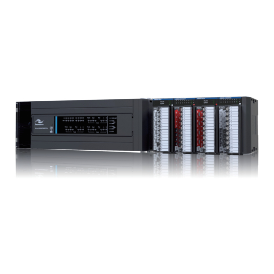
1 Product Information 1.3 Product Structure 1.3.1 H3U-3232MT/R or H3U-0808PMRTA 5) I/O status LED 6) I/O protection cover 4) USB port cover 9) Tail cover buckle 1) Cover 8) Extension module tail cover 2) COM0 communication PWR+BAT 00 01 02 03 04 05 06 07 20 21 22 23 24 25 26 27... - Page 8 1 Product Information 1.3.2 H3U-1616MT/R-XP 2) RUN switch cover 3) I/O status LED 4) I/O protection cover 7)Tail cover buckle 6) Extension module tail cover 1) CAN communication port cover 7) Tail cover buckle 5) DIN slot installation buckle 8) RUN/STOP switch 16) Ethernet communication RJ45 port 9) COM0 (RS422/485) port 17) RS485 communication terminal...
- Page 9 1 Product Information 185.00 10.00 95.00 Mounting hole 4.50x4 φ (Unit: mm) 1.4.2 H3U-1616MT/R-XP 170.00 10.00 (Unit: mm) 135.00 10.00 90.00 Mounting hole 4.50x4 φ (Unit: mm) - 8 -...
-
Page 10: Chapter 2 Installation
2 Installation Chapter 2 Installation 2.1 Installation Environment Item Specifications Ambient Running: -5~55°C, storage: -25~75°C temperature Relative Running: 5~95%RH (non-condensing) humidity One-way Frequency Acceleration amplitude (Hz) (m/s (mm) Ten times in 10~57 0.035 When DIN rail each of the X, Y Vibration is installed and Z direction... - Page 11 2 Installation To ensure properly ventilation, the distance A between the PLC and modules should be larger than 50 mm. Other device Other device - 10 -...
-
Page 12: Installation Procedure
2 Installation 2.3 Installation Procedure The H3U series PLC can be installed on DIN rails or mounted on wall using M4 screws. 2.3.1 Installation of DIN Rail (DIN46277, 35 mm wide) Fix the DIN rail on the mounting surface in the control cabinet;... - Page 13 2 Installation 2.4 Installation of Expansion Modules Pull the lock catch on the expansion module to the direction shown in the following figure. Push the expansion module to the PLC. Pull the lock catch back to lock it. Unlock 2.5 Dismantling Connection Terminals When dismantling the barrier terminal block, loosen the screws on both sides concurrently to remove the terminal block horizontally.
- Page 14 2 Installation 2.6 Installation of Lithium Cell Follow the procedure to install a new lithium cell if necessary. 2.7 Installation of TF Card 2.8 Installation of COM0 and Ethernet Cables - 13 -...
- Page 15 2 Installation Setting of DIP switch: when you need to set the Ethernet IP address, CAN communication Baud rate and station number, you need to open the cover on the left side as shown in the following figure. Press with both hands and rotate - 14 -...
-
Page 16: Chapter 3 Wiring
3 Wiring Chapter 3 Wiring 3.1 I/O Terminals 3.1.1 Layout of Terminals Terminals of H3U-3232MT S/S1 S/S0 Y06 COM5 Y11 Y16 COM7 Y21 COM9 COM0 Y01 COM1 COM2 COM3 COM4 Y07 Y12 COM6 Y15 Y22 COM8 Y25 Terminals of H3U-1616MT/R S/S0 S/S1 X 00... - Page 17 3 Wiring 3.1.2 Functions of Terminals Function Terminals Remarks to the two-phase AC power supply, 85~264 VAC, Power input L, N, PE 220 VAC(Rated) Provide +24 VDC power supply externally. Usually, it provides power Power output 24V, 0V supply to DI/DO terminals and external sensors. Max.
-
Page 18: Input Wiring
3 Wiring Function Terminals Remarks Detection voltage: 24 VDC1 X00-X07 on H3U- Hi-speed 3232MT/ H3U- Input resistance: 3.3 kΩ input 1616MT-XP Max. frequency: 200 kHz (Ax+, Ax-) and Input mode: Differential input, leakage/source (Bx+, Bx-) on H3U- type; Hi-speed 0808PMRTA, (PGx+, differential PGx-) can serve as Detection voltage: When the voltage is larger than... - Page 19 3 Wiring 3.2.3 Differential Input Wiring User signal wiring 24V+ 24 VDC auxiliary power 24V- Sensor PGx+ PGx+ PGx- PGx- Equivalent circuit in PLC Equivalent circuit in main module PLC main module Sink input wiring Standard wiring User signal wiring 24V+ 24 VDC auxiliary power...
-
Page 20: Output Wiring
3 Wiring 3.3 Output Wiring 3.3.1 Normal/Hi-speed Transistor Output Wiring Equivalent circuit DC5 V power in the PLC Output supply Working power supply of the group 0 COM0 internal logic circuit Output group 1 COM1 Output group 3 COM3 3.3.2 Wiring of Relay Outputs Equivalent circuit 24Vdc in the PLC... - Page 21 3 Wiring 3.3.3 Wiring of Hi-Speed Differential Outputs FP1+ FP1- RP1+ in the RP1- Interior of the PLC 3.3.4 Wiring of Normal Transistor Zero-Clearing NPN Outputs Equivalent circuit in the PLC DC5 V power supply CLR0+ CLR0- CLR1+ CLR1- CLR2+ CLR2- The normal transistor zero-clearing NPN output is the motion control pin of H3U- 0808PMRTA.
- Page 22 3 Wiring Name Description CAN communication power +24V,CGND supply, setting range is between 9-30 V CAN communication cable, the reference level is CGND. CGNDs COM1 CANL,CANH must be connected to each other when there are multiple stations. It is the shield layer, which should be connected according to the CAN communication port actual need.
-
Page 23: Chapter 4 Quick Setup
4 Quick Setup Chapter 4 Quick Setup 4.1 Tools Requirements Hardware Tool Kit USB2.0 (Type-A) to Laptop USB download cable for PLC (Inovance Part No.: H2U-USB- CAB) USB2.0 (Mini-B) to PLC Laptop for programming & download (Windows 7, Windows 8, Window 10) -
Page 24: Hardware Connection
4 Quick Setup 4.2 Hardware Connection 220VAC,50Hz Single-phase power supply 20 21 22 23 24 25 30 31 32 33 34 35 01 01 02 03 04 05 06 07 10 11 12 13 14 15 16 17 H2U-USB-CAB 4.3 Installation of AutoShop Step 1: Double click the , the present version is V2.62 for English. - Page 25 4 Quick Setup Step 3: Click “Next”. Step 4: Click “Next". - 24 -...
- Page 26 4 Quick Setup Step 5: Click “Install”. Step 6: Wait until the installation complete, click “Close”. - 25 -...
- Page 27 4 Quick Setup 4.4 Program Download Procedure Step 1: Power on the PLC. Double-click the “AutoShop”. Choose “File” > “New Project” from the main menu. - 26 -...
- Page 28 4 Quick Setup Step 2: Set as follows. Step 3: Choose “Tools” > “Communication Setting” from the main menu. - 27 -...
- Page 29 4 Quick Setup Step 4: Follow below steps. Step 5: Click “OK”. - 28 -...
- Page 30 4 Quick Setup Step 6: Follow below steps. Step 7: Click “Download”. - 29 -...
- Page 31 4 Quick Setup Step 8: The output window indicates the download executed. Step 9: 1.Switch to “RUN”. 2.The RUN light is ON. Step 10: 1.Click “monitor” widget to start monitoring program. 2.The lamps of PLC Status and Fault turn green. - 30 -...
- Page 32 4 Quick Setup Tips: Strongly recommend to set Display as below. - 31 -...
-
Page 33: Chapter 5 Troubleshooting
5 Troubleshooting Chapter 5 Troubleshooting 5.1 System Error Code D8060 Error Code Content D8060 I/O range or setting error 1000-1377 X input signal error, serial number error or exceeding limit 0000-0377 Y input signal error, serial number error or exceeding limit 5.2 System Error Code D8061 Error Code Content... - Page 34 5 Troubleshooting 5.3 System Error Code D8062 Error Code Content Communication error in control panel or program D8062 connection port 6200-6279 serial communication and configuration error codes 6201 Receiving timeout 6202 CAN transmitting busy 6203 CAN receiving busy 6204 Data format incorrect 6205 Instruction incorrect 6206...
- Page 35 5 Troubleshooting Error Code Content 16260-16279 motion control configuration error code 16260 Mechanical unit setting value incorrect 16261 Electronic gear ratio setting value incorrect 16262 Cam table not configured in software being used 16263 No external input master axis selected for electronic cam Electronic cam slave axis speed exceeding maximum 16264 output speed allowed...
- Page 36 5 Troubleshooting Error Code Content 6307 Reserved 6308 Reserved 6309 Reserved 6310 Reserved 6311 Reserved 6312 Parallel control (1:1) protocol character incorrect 6313 Parallel control (1:1) protocol sum incorrect 6314 Parallel control (1:1) protocol format incorrect 6315 Parallel control (1:1) protocol communication timeout 6316-6329 Reserved Modbus slave address setting incorrect, address larger than...
- Page 37 5 Troubleshooting Error Code Content 16313 Frame length error 16314 Frame timeout error 16315 Frame not recognized by slave (only for master) 16316 IP address illegal 16317-16319 Reserved 16320-16339 Extension module communication error code 16340-16359 USB communication error code 16360-16379 Control panel and interface communication error code 16380-16399 Reserved...
- Page 38 5 Troubleshooting 5.6 System Error Code D8065 Error Code Content D8065 User program grammar error 6501 Reserved 6502 Reserved 6503 Instruction parameter error 6504 Label definition repeated 6505 Reserved 6506 Non-defined instruction used 6507 Label P definition incorrect 6508 Label I definition incorrect 6509 Reserved 6510...
- Page 39 5 Troubleshooting Error Code Content D8066 User program logic loop error 6622 No NEXT instruction 6623 No MC instruction 6624 No MCR instruction 6625 STL used for above consecutive nine times 6626 Certain instructions cannot be used in STL-RET 6627 No RET instruction 6628 Instructions useless in main program...
- Page 40 5 Troubleshooting Error Code Content 6711 Soft element using in instruction repeated or conflict 6712 Non-defined interrupt used in system 6713-6719 Reserved 6720 CALL instruction SRET not in a match 6721 Parameter incorrect in subroutine program with parameters 6722 Manipulator instruction port function conflict 6723-6729 Reserved 6730...
- Page 41 5 Troubleshooting Error Code Content 6764 High-speed input instruction data exceeding range 6765 High-speed output instruction element exceeding range 6766 High-speed output instruction data exceeding range Conflict in comparison objects setting of high-speed 6767 interruption comparison instruction 6768 Reserved 6769 Reserved 6770 High-speed output instruction port repeated or conflict...
-
Page 42: Revision History
Revision History Date Version Change Description First issue. Firmware version: Jan. 2017 ● Standard models = 24306-0000 ● H3U-0808PMRTA = 25305-0000 May 2017 Modified the 24 V input wiring diagrams.
Need help?
Do you have a question about the H3U Series and is the answer not in the manual?
Questions and answers