Table of Contents
Advertisement
Advertisement
Table of Contents

Related Manuals for Kaba SIMPLEX LD470


Summary of Contents for Kaba SIMPLEX LD470
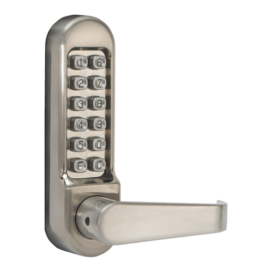
- Page 1 LD470 Pushbutton Lock Installation Instructions...
-
Page 2: Table Of Contents
J. Trouble Shooting ............10 Warnings and Cautions Important: Carefully inspect windows, doorframe, door, lights, etc. to ensure that the recommended procedures will not cause damage. Kaba Access Control’s warranty does not cover damages caused by installation. Caution: Wear safety glasses when preparing door. -
Page 3: Checklist
CHECKLIST Use this checklist to make sure that everything has been included. J A—Outside unit B—Inside unit C—Gaskets (2) D—Universal trim plate (2) E—Spindles (3 lengths) F—Latch G—Strike plate H—Latch and strike screws (4) J—Tweezers K—Mounting screws (8) (4 lengths) L—Spare tumblers –... -
Page 4: Determining The Hand Of Your Door
DETERMINING THE HAND OF YOUR DOOR Many of the installation instructions refer to RH - Right Hand the handing of your door. The hand of the door is determined with the door in the closed position, from the exterior or pushbutton side of the door. A) Right Hand Door. -
Page 5: Marking The Template And Drilling The Door
A-11 Using the hex wrench supplied, remove the set screw from the lever in question. A-12 Remove the lever and rotate it 180º. Slide the lever back onto the lock. A-13 Using the hex wrench supplied, reinstall the set screw. Assure the lever rotates freely. -
Page 6: Installing The Spindle
D. INSTALLING THE SPINDLE Note: Assurance that the proper spindle is used is extremely critical. If the wrong spindle is used, binding or lockout can occur. For doors ranging in thickness from 1 ⁄ " Viewed from (35 mm) to 1 ⁄... -
Page 7: Installing The Strike Plate
E-9 Before final tightening, make sure the code works and all features on the unit work as intended. Note: Do not close the door until the lock has been tested and you are confident it works properly. E-10 Tighten the mounting screws firmly, being careful not to over tighten the screws, as this may cause the lock to function poorly or not at all. -
Page 8: Changing The Code
G. CHANGING THE CODE “latchbolt” Remove the lock from the door. G-2 Remove the 4 retaining (red) screws from “deadlatch” the back of the outside unit assembly. Take extra care to keep the outside unit assembly on a flat surface when you are removing the cover plate because there are many small components inside. - Page 9 ⁄ ” (70 mm) Backset ONLY. From outside, fo ⁄ ” (60 mm) Backset ONLY. From outside, f ⁄...
- Page 10 old along the right edge of the door old along the right edge of the door 1” (25 mm) ⁄ ” (159 mm) Hole ⁄ ” (21.5 mm)
-
Page 13: Using The Passage Function
H. USING THE PASSAGE FUNCTION H-1 Enter the user access code, followed by the “F” button. H-2 Rotate the outside lever repeatedly. The latch should retract each time. You are now in the passage mode. NOTE: To disable the passage function, depress the “F” button, followed by the “C”... -
Page 14: Trouble Shooting
J. TROUBLE SHOOTING Installation Issues: The latch cannot be withdrawn when entering the code The lock has been fitted to a left-hand hung door All locks were set to fit right-hand hung doors. The lock needs to be removed from the door and reversed. Refer to instructions. Both the inside and outside lever retract when turned towards the door frame. - Page 15 Kaba Access Control analysis to be defective during this period. Our only liabili- ty, whether in tort or in contract, under this warranty is to repair or replace products that are returned to Kaba Access Control within the one (1) year war- ranty period.
- Page 16 Kaba Access Control 2941 Indiana Avenue Winston-Salem, NC 27105 USA Tel: (800) 849-8324 (336) 725-1331 Fax: (800) 346-9640 (336) 725-3269 www.kabaaccess.com LD470 1207...
Need help?
Do you have a question about the SIMPLEX LD470 and is the answer not in the manual?
Questions and answers