Table of Contents
Advertisement
Advertisement
Table of Contents

Related Manuals for Kaba Simplex 506 Series


Summary of Contents for Kaba Simplex 506 Series
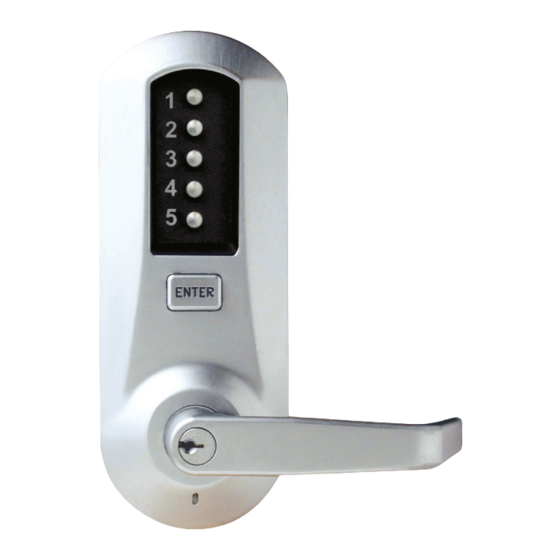
- Page 1 Simplex 506x Mortise ® Installation Instructions...
-
Page 2: Table Of Contents
Warnings and Cautions Important: Carefully inspect windows, door frame, door, lights, etc. to ensure that the recommended procedures will not cause damage. Kaba Access Control’s warranty does not cover damages caused by installation. Caution: Wear safety glasses when preparing door. -
Page 3: Tools Required
Introduction The purpose of this manual is to instruct the installer on the proper installation procedure for the Simplex 506x American Steel Mortise (ASM) locks. These instructions pertain to models with and without deadbolts. For models without deadbolts, please disregard any references to a thumbturn in the instructions. OPERATIONAL NOTE: The Simplex Mortise lock is almost identical to the Simplex 5000 Cylindrical lock with the following exceptions:... -
Page 4: Exploded Install Parts
Installation Qualifications These instructions are designed for use by maintenance professionals or lock installers who are familiar with common safety practices and competent to perform the steps described. Kaba Access Control is not responsible for damage, injury or malfunction due to incorrect installation. For technical assistance please call... -
Page 5: Mortise Handing
DOOR HANDING Some locks also require you to specify door handing. To determine handing, face the door from the exterior (access) side and select the corresponding dia- gram below. Inside Inside Inside Inside A. MORTISE HANDING For LH (left hand) and For RH (right hand) and RHR (right hand reverse) LHR (left hand reverse) - Page 6 A-1.1 Continued Clip Clip Lock Position Unlock Position 3. Push in the latch bolt (L) to the middle of its stroke, and hold it there. (Continue Step 1 and 2 to the right) Hold the latch (L) inside the mortise, and insert the tail- piece retaining tool (S) so that the tailpiece (T) will not drop inside the mortise case.
- Page 7 Release the latch to the middle of the stroke and hold it there. Use a small screwdriver to push the lock mechanism back on lock position (see step 1 and 2). IMPORTANT: The lock mechanism has to be horizontal on lock position. F (tooth) 5. Release the latch bolt (L). Position F (tooth) the latch bolt so that the bottom F (tooth)
-
Page 8: Door Preparation
F (tooth) A SM The mortise should look like the diagram mortise at the right. (Check the orientation of the latch bolt and auxiliary latch.) Check bottom view the bevel of the mortise and change it if required as described in section B-8 on page 14. - Page 9 The axis of rotation of the handle is level with the bottom lip of the strike. B-2 Align the template along the vertical Handle center line of the mortise (CL) at the Height desired handle height, and tape it to the door.
-
Page 10: Installing The Strike
B-8 Check the bevel of the mortise faceplate. If adjustment is required, loosen the two bevel screws and adjust mortise front plate angle to match the bevel of the door (R). B-9 Re-tighten screws. B-10 Install the mortise with two 1 “ Logo Phillips screws provided (Q). B-11 Install mortise faceplate with the two 8-32 x ⁄... -
Page 11: Installing Outside Unit Assembly
C-4 Position the strike against the door frame and align it with the mounting screw holes. Then mark the outline of the strike. C-5 Remove any material from within the strike outline (a) so that the strike will be flush with the door frame. - Page 12 ® LIMITED WARRANTY Kaba Access Control warrants this product to be free from defects in material and workmanship under normal use and service for a period of three (3) years. Kaba Access Control will repair or replace, at our discretion, 5000 Series Locks found by Kaba Access Control analysis to be defective during this period.
- Page 15 Notes...
-
Page 16: Installing The Inside Lever
E-2 If the lock comes with a thumbturn for passage (B), insert the thumbturn through the inside housing (C) and secure using the spring clip (D). N ote: The tailpiece of the passage actuator (A) is scored on several places to allow you to easily break off the section that extends beyond the required length to engage the passage set cam. E-3 Hold the tailpiece (A) firmly with a pair of pliers, adjacent to the desired break line. With a second pair of pliers, grip the tailpiece on the other side of the scored line and bend up and down until it... -
Page 17: Changing Key-In-Lever Cylinder
G-2 Determine the proper tailpiece (d) from the chart below for your KIL cylinder. You must use a Kaba tailpiece. The K 2 tailpiece is preassembled with the Kaba 1599. TAILPIECE KIL CYLINDER Abloy 5277, Abloy 5477, Assa 65691, Kaba 1539, Kaba Gemini 4730 Assa 65611, Australian: Kaba experT 107K5 &... -
Page 18: Installing / Removing Outside Lever (Key-In-Lever) Kil
H. INSTALLING / REMOVING OUTSIDE LEVER (Key-In-Lever models only)(For interchangeable and removable cores proceed to section I) Correct Incorrect Position Position Note: Installing levers to the unit assemblies before mounting the unit assemblies may KIL Lever Sleeve ease initial installation. H-1 Make certain the lever catch is up as shown (c). Position the lever sleeve (f) tab correctly with the respective notch on the lever. - Page 19 shipped with the lever sleeve already installed in the lock housing. When installing the lever, ensure it is oriented to engage the lever sleeve to accommodate desired lock handing as shown. Insert the outside lever (b) until it is flush to the outside unit assembly (a).
- Page 20 For ASSA/Medeco/Yale interchangeable/removable cores, the tailpiece must be prepped for the desired length before installation. Notice the score marks on the flat portion YALE 6 & 7 PIN, of the ASSA/Medeco/Yale tailpiece. Using EXIT & MORTISE MEDECO 5 PIN, the diagram to the right, locate the score EXIT &...
-
Page 21: Testing The Operation Of The Lock
J. TESTING THE OPERATION OF THE LOCK Rotate in the inside lever downward and hold. Ensure that the latch is fully retracted. Release the lever and the latch should return to the fully extended position. With code entered, the lever only rotates downward. J-2 Enter the factory set combination: Depress buttons 2 and 4 at the same time (&... - Page 22 Insert the release tool (a) through hole in number pad and gently lift up loop end of the tool to depress the code change button until you hear a click; remove tool and do not press any buttons (proceed to K-3). **This Step Is Very Important** Rotate lever (d) once, and only once to clear the old combination;...
-
Page 23: How To Reset Lost Or Unknown Combination
Warning: Since this procedure is of a technical nature, only technically trained personnel in the lock and hardware field should undertake this operation. For further assistance, call the Kaba Access Control technical support line at 800-849-TECH (8324) or 336-725-1331 between 8AM and 5PM Eastern Standard Time, Monday through Friday (except holidays). - Page 24 Resetting and Recovery of Current Combination To reset the code gears (a), each one of the 5 “L” shaped legs (b) of the unlocking slide (c) must engage snugly with the corresponding code gear pocket (d) next to it. Position the chamber in one hand, as shown.
- Page 25 Clearing the Current Combination and Setting a New Combination Note: Align the code gear pockets with the “L” shaped legs. Depress the combination change button (i) located on top of the combination chamber and release. Rotate the reset cam back toward you with your finger (toward the key stems) as far as it will go and release. Enter your new combination by depressing the key stem corresponding to the first number (1 through 5) of your combination.
-
Page 26: Installing Rubber Bumpers
INSTALLING RUBBER BUMPERS Close the door and apply pressure making sure the deadlatch rests on the strike plate. Standing on the frame (door stop) side of the door, check for gaps between the door and the frame on the three sides of the frame (left, right, and top). - Page 27 SYMPTOM POSSIBLE CAUSE REMEDY 4. Correct combination is Failed to depress the Always depress and release depressed, but the latch “ENTER” button. the “ENTER” button after does not retract. depressing the correct combination. 5. Cannot remove key Key was rotated 180 Rotate key from outside lever —...
- Page 28 Kaba Access Control 2941 Indiana Avenue Winston-Salem, NC 27105 USA Tel: (800) 849-8324 (336) 725-1331 Fax: (800) 346-9640 (336) 725-3269 www.kabaaccess.com LIT1051 1012...
Need help?
Do you have a question about the Simplex 506 Series and is the answer not in the manual?
Questions and answers