Table of Contents
Advertisement
Available languages
Available languages
Quick Links
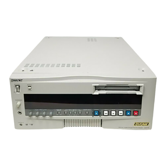
SDI Output Board
取扱説明書
2
ページ
Operating Instructions
Mode d'emploi
Page 19
Bedienungsanleitung
Istruzioni per l'uso
お買い上げいただきありがとうございます。
電気製品は、安全のための注意事項を守らない
警告
と、火災や人身事故になることがあります。
•
ご使用にあたっては、デジタルビデオカセットプレーヤー
本体に付属の取扱説明書の 「安全のために」 と 「
「
注意」 をよくお読みください。お読みになったあとは、
いつでも見られるところに必ず保管してください。
•
本基板の取り付けは、必ずお買い上げ店またはソニーの
サービス窓口にご依頼ください。
DSBK-100/100P
© 1997 by Sony Corporation
Page 11
Seite 27
pagina 35
警告」 、
3-859-819-02(1)
J
EN
F
D
I
Advertisement
Chapters
Table of Contents

Subscribe to Our Youtube Channel
Related Manuals for Sony DSBK-100


Summary of Contents for Sony DSBK-100
- Page 1 Operating Instructions Page 11 Mode d’emploi Page 19 Bedienungsanleitung Seite 27 Istruzioni per l’uso pagina 35 お買い上げいただきありがとうございます。 電気製品は、安全のための注意事項を守らない 警告 と、火災や人身事故になることがあります。 • ご使用にあたっては、デジタルビデオカセットプレーヤー 本体に付属の取扱説明書の 「安全のために」 と 「 警告」 、 「 注意」 をよくお読みください。お読みになったあとは、 いつでも見られるところに必ず保管してください。 • 本基板の取り付けは、必ずお買い上げ店またはソニーの サービス窓口にご依頼ください。 DSBK-100/100P © 1997 by Sony Corporation...
- Page 2 日本語 警告表示の意味 取扱説明書および製品では、 次のよ う な表示を していま す。 表示の内容をよく 理解してから本文をお読みく ださ い。 警告 この表示の注意事項を守らないと、 火災や感電などによ り死亡や大けがなど人身事故につながる こ とがあ り ます。...
- Page 3 目次 取り扱い説明 概要 ....................DSBK-100 の構成品 .................. 4 設置説明 警告 ....................取り付け ..................... 準備 ......................5 取り付け手順 ....................6 日 本 語...
- Page 4 概要 SDIアウ ト プッ ト ボー ドDSBK-100は、 ソニーデジタルビデオカセッ ト プレーヤーDSR-60のた めのオプシ ョ ン基板です。 本基板をDSR-60に取り付けるこ とによ り、 SDI(シリ アルデジタル イ ンターフェース)フ ォーマッ トのデジタルビデオ/オーディ オ信号の出力が可能になり ます。 本基板を取り付けたあとの接続や出力信号の仕様については、 DSR-60の取扱説明書をご 覧く ださい。 DSBK-100 の構成品 DSBK-100は、下記の品目で構成されています。 SDI-28 基板 ケーブル 組 コネクターの色が黒・赤のものが 組 ノイズフィルター コネクターパネル ネジ...
- Page 5 警告 お客様へ 以下の設置説明 ( 「取り付け」 の項) は、 特約店およびソニーのサービス窓口用の設置説 明書です。 お客様がこの設置説明書に記載された作業を行う と、火災や、感電やけがなどの人身事 故につながる こ とがあ り ます。 お客様自身では絶対に取り付け作業をしないでく ださい。 本基板の取り付けは、 必ずお買い上げ店またはソニーのサービス窓口にご依頼く ださい。 取り付け 準備 取り付け作業を始める前に、 SDI-28 基板にケーブルを接続しておいてく ださい。 • コネク ターが黒色のケーブルを、 基板上の BLACK と表示されているコネクターに接続 します。 • コネク ターが赤色のケーブルを、 基板上の RED と表示されているコネクターに接続し ます。...
- Page 6 ています。 スロ ッ ト フ レームの刻印 ← DV で確認してく ださい。 ご注意 取り外した基板は、 金属カバーを下側 にして、机やテーブルの上面など平 坦な面に静かに置いてく ださい。 SDI-28 基板 SDI-28 基板のコネク ターを、 DV-17 基 の方向から見て、コネクター間 DV-17 基板 板のコネク ターにしっかり と差し込む。 にすき間ができないように完全に 結合させる。 すき間がない。 ① すき間がある。 DV-17 DSBK-100に付属のネジ2 本で、 SDI- 基板の金属カバー 28基板とDV-17基板を互いに固定す る。 金属カバーに開いている穴の中を 見て、周囲に白い斜線が見えるネ ジ穴を選ぶ。 SDI-28 基板...
- Page 7 「準備」 (5 ページ) で SDI-28 基板に 接続した 2 本のケーブルを、図のよ DV-17 基板 う なルー トで DV-17 基板上にはわせ、 配線止め (2 本) を巻きつけて固定 する。 SDI-28 基板 配線止め DV-17基板を、 DSR-60の基板スロ ッ ト に戻す。 両端のレバーを倒し、両手で確実に 奥まで差し込んでく ださい。 SDI-28 基板に接続したケーブルを基 板スロッ トの後面パネル側にある溝に 入れる。 DSR-60 の後面パネルのブラ ンクパネ ルの2か所のネジとワ...
- Page 8 取り付け 2本のケーブルの端をブラ ンクパネル を外したあとの穴から外に出し、 コネ ク ターパネルに接続する。 赤色のコネクター ご注意 黒色のコネクター 接続に際しては、ケーブルのコネク ターの色に注意して、必ず図に示す 並び順で接続してく ださい。 コネクターパネル コネクターパネルをDSR-60の後面パ ネルに取り付ける。 ケーブルを内側に引きながら、 コネク ターパネルを差し込んで、左にずら し、手順 で外した 2 本のネジとワ ッ シャーで、コネクターパネルを固定し ます。 コネクターの色がそれぞれ赤色と黒 ケーブル収納スペース 色の 2 本のケーブルを、 DSR-60 の前 面から見て左側にある2 つのク ランプ クランプ に止め、たるんだ部分をノ イ ズフ ィ ル ノイズフィルター...
- Page 9 手順 で取り外した基板押さ え(1)お 基板押さえ よび (2) を取り付け、次に DSR-60 の 天板を取り付ける。 ネジ 基板押さ え (1) には 6 対のツメがあ り ネジ ます。 これらのツメが対応の基板の上 ネジ 縁をはさむよ う に取り付けてく ださい。 基板押さえ...
-
Page 11: Table Of Contents
For the customers in Canada This Class A digital apparatus complies with Canadian ICES-003. Table of Contents Overview ................12 Components of the DSBK-100/100P ........ 12 Installation ............... 13 Preparations ............... 13 Fitting Procedure ............... 14... -
Page 12: Overview
Overview The DSBK-100/100P SDI Output Board is an option for the Sony DSR-60/ 60P Digital Videocassette Player. When this option is fitted in a DSR-60/ 60P, it becomes possible to output digital video and audio signals in the SDI (Serial Digital Interface) format. -
Page 13: Installation
Installation Preparations Before beginning the installation procedure, connect the cables to the SDI- 28 board. • Connect the cable with the black connectors to the connector labeled “BLACK” on the board. • Connect the cable with the red connectors to the connector labeled “RED”... -
Page 14: Fitting Procedure
Installation Fitting Procedure Remove the top cover from the Board retainer (1) Top cover DSR-60/60P, then remove the Screw board retainers (1) and (2). Screw Screw DSR-60/60P Board retainer (2) Remove the DV-17 board. Seen from the front of the Raise the levers, then pull out the board. - Page 15 With the two screws supplied Metal cover with the DSBK-100/100P, fasten the SDI-28 board to the DV-17 board. Looking into holes in the metal cover, select the screw holes surrounded by white hatching. SDI-28 board Pass the two cables (connected to the SDI-28 board in the “Preparations”...
- Page 16 Red connector the connector panel, one of the Black connector components of the DSBK-100/ 100P. Note Be careful to match the cable Connector panel connector colors, and connect them in the sequence shown in the figure.
- Page 17 Fasten the pair of cables with Partitioned space red and black connectors in the left-side pair of clamps as seen Clamp from the front of the DSR-60/ Noise filter 60P, then stow the noise filter and the slack portions of cables neatly in the left-side partitioned space.
- Page 19 Français Pour les utilisateurs au Canada Cet appareil numérique de la classe A est conforme à la norme NMB-003 du Canada. Sommaire Aperçu ................20 Composants de la DSBK-100/100P ........20 Installation ............... 21 Préparatifs................21 Procédure d’installation............. 22...
-
Page 20: Aperçu
Aperçu La carte de sortie SDI DSBK-100/100P est une option destinée au lecteur de cassettes vidéo numérique DSR-60/60P Sony. Son insertion dans le DSR-60/60P permet la sortie de signaux vidéo et audio en format SDI (Serial Digital Interface). Voir le mode d’emploi du DSR-60/60P pour les spécifications et connexions des signaux de sortie. -
Page 21: Installation
Installation Préparatifs Avant de commencer la procédure d’installation, raccorder les câbles à la carte SDI-28. • Raccorder le câble à connecteurs noirs au connecteur “BLACK” sur la carte. • Raccorder le câble à connecteurs rouges au connecteur “RED” sur la carte. -
Page 22: Procédure D'installation
Installation Procédure d’installation Retirer le cache supérieur du Retenue de carte (1) Cache supérieur DSR-60/60P, puis retirer les retenues de carte (1) et (2). DSR-60/60P Retenue de carte (2) Retirer la carte DV-17. Vu de l’avant du DSR-60/60P, Soulever les leviers pour la carte DV-17 se trouve dans retirer la carte. - Page 23 Fixer la carte SDI-28 à la carte Cache métallique DV-17 avec les deux vis fournies avec la carte DSBK- 100/100P. Regarder dans les trous du cache métallique, et sélectionner les trous à vis entourés de hachures blanches. Carte SDI-28 Passer les deux câbles (raccordés à...
- Page 24 à connecteurs, un des composants de la carte Connecteur rouge DSBK-100/100P. Connecteur noir Remarque Bien faire correspondre les couleurs des connecteurs, et les raccorder dans l’ordre indiqué...
- Page 25 Fixer la paire de câbles à Espace cloisonné connecteurs rouges et noirs sur le côté gauche de la paire de Serre-câble serre-câbles, vu de l’avant du Filtre antibruit DSR-60/60P, puis ranger soigneusement le filtre antibruit et les parties déliées des câbles dans l’espace cloisonné...
- Page 27 Deutsch Für Kunden in Deutschland Dieses Produkt kann im kommerziellen und in begrenztem Maße auch im industriellen Bereich eingesetzt werden. Dies ist eine Einrichtung, welche die Funk-Entstörung nach Klasse B besitzt. Inhaltsverzeichnis Kurzbeschreibung ............28 Die Komponenten der DSBK-100P ........28 Installation ...............
-
Page 28: Kurzbeschreibung
Kurzbeschreibung Die SDI Output Board DSBK-100P ist eine optionale Leiterplatte für den Einbau in einen digitalen Videospieler DSR-60P von Sony. Die Installation dieser Leiterplatte in den DSR-60P ermöglicht die Ausgabe digitaler Video- und Audiosignale im SDI-Format (SDI = Serial Digital Interface). -
Page 29: Installation
Installation Vorbereitungen Schließen Sie vor der eigentlichen Installation die Kabel an die Leiterplatte SDI-28 an. • Schließen Sie das Kabel mit den schwarzen Anschlüssen an den mit „BLACK“ gekennzeichneten Anschluß der Leiterplatte an. • Schließen Sie das Kabel mit den roten Anschlüssen an den mit „RED“ gekennzeichneten Anschluß... -
Page 30: Einbauverfahren
Installation Einbauverfahren Entfernen Sie die obere Obere Abdeckung Abdeckung des DSR-60P, und Leiterplattenhalterung (1) Schraube entfernen Sie die Leiterplattenhalterungen (1) Schraube und (2). Schraube DSR-60P Leiterplattenhalterung (2) Entfernen Sie die Leiterplatte DV-17. Von der Frontseite des DSR- Die Hebel nach oben drücken, und die 60P betrachtet, befindet sich Leiterplatte herausziehen. - Page 31 Sichern Sie die SDI-28 mit den Metallabdeckung zwei Schrauben, die zum Lieferumfang der DSBK-100P gehören, an der Leiterplatte DV-17. Die weiß umrandeten Bohrungen in der Metallabdeckung als Schraublöcher verwenden. SDI-28 Leiterplatte Führen Sie die zwei Kabel (die unter „Vorbereitungen“ an die DV-17 Leiterplatte SDI-28 angeschlossen wurden) über die Leiterplatte DV-17...
- Page 32 Installation Lösen Sie die zwei Schrauben und Unterlegscheiben von der Abdeckplatte an der Rückwand des DSR-60P. Schieben Sie die Abdeckplatte nach rechts, und ziehen Sie sie heraus. Hinweis Bewahren Sie die Abdeckplatte auf. Abdeckplatte Ziehen Sie die zwei Kabel durch die Öffnungen hinter der Abdeckplatte heraus, und schließen Sie sie an das Roter Anschluß...
- Page 33 Sichern Sie das Kabelpaar mit Schachtfreiraum den roten und schwarzen Kabelklemmen Anschlüssen von der Frontseite des DSR-60P betrachtet mit Rauschfilter dem linken Paar Kabelklemmen, und verstauen Sie dann das Rauschfilter und die überschüssigen Kabelteile in den linken Schachtfreiraum. Bringen Sie die in Schritt 1 entfernten Leiterplattenhalterung (1) Leiterplattenhalterungen (1)
- Page 35 Presentazione La scheda di uscita segnali SDI DSBK-100P è un accessorio opzionale per il lettore di videocassette digitale DSR-60P Sony. Quando questa scheda opzionale è installata in un DSR-60P, diventa possibile emettere segnali video e audio digitali nel formato SDI (interfaccia seriale digitale).
- Page 36 Installazione Preparativi Prima di iniziare il procedimento per l’installazione, collegare i cavi alla scheda SDI-28. • Collegare il cavo con i connettori neri al connettore con la scritta “BLACK” sulla scheda. • Collegare il cavo con i connettori rossi al connettore con la scritta “RED” sulla scheda.
- Page 37 Procedimento per l’installazione Rimuovere il coperchio Fermo delle schede (1) Coperchio superiore superiore dal DSR-60P, quindi Vite rimuovere i fermi delle schede (1) e (2). Vite Vite DSR-60P Fermo delle schede (2) Rimuovere la scheda DV-17. Guardando dal davanti del Alzare le levette, e quindi DSR-60P, la scheda DV-17 si estrarre la scheda.
- Page 38 Installazione Con le due viti in dotazione Coperchio di metallo alla DSBK-100P, fissare la scheda SDI-28 alla scheda DV- Guardando nei fori sul coperchio di metallo, scegliere i fori per le viti circondati dal tratteggio bianco. Scheda SDI-28 Far passare i due cavi (collegati alla scheda SDI-28 Scheda DV-17 nella fase “Preparativi”) sopra...
- Page 39 Rimuovere le due viti e le due rondelle dalla piastra di copertura sul pannello posteriore del DSR-60P. Far scorrere la piastra di copertura verso destra e quindi rimuoverla. Nota Conservare la piastra di copertura. Piastra di copertura Far passare i due cavi attraverso i fori esposti in seguito alla rimozione della piastra di copertura e collegarli...
- Page 40 Installazione Fissare la coppia di cavi con Comparto connettori rossi e neri nella Morsetto coppia di morsetti a sinistra guardando dal davanti del Filtro antirumore DSR-60P, quindi riporre il filtro antirumore e le parti in eccesso dei cavi nel comparto sinistro.
Need help?
Do you have a question about the DSBK-100 and is the answer not in the manual?
Questions and answers