Table of Contents
Advertisement
Quick Links
INSTRUCTION
MANUAL
INSTRUMENT SOFWARE 3.0
Norsonic has always been at the
forefront introducing new technology
to sound level meters. The Nor150
Sound and Vibration Analyser sets
a new standard in user-friendliness.
Featuring the largest colour touch
screen in a handheld meter on the
market today, the Nor150 provides
the user-friendliness of a smart phone.
Further features include built in web
server, camera, GPS, sound recording,
voice and text notes, sophisticated
marker handling and event triggers in
addition to high resolution time profi le
and multi-frequency spectra bringing
the sophistications normally found in
laboratory instrumentation out in the
fi eld. The instrument is designed to
cover a variety of applications besides
being a sophisticated sound level
meter. This instruction manual covers
software version 3.0, noise monitoring,
building acoustics and sound intensity
market.
nor150
SOUND & VIBRATION ANALYSER
Advertisement
Table of Contents

Related Manuals for Norsonic nor150


Summary of Contents for Norsonic nor150
- Page 1 MANUAL INSTRUMENT SOFWARE 3.0 Norsonic has always been at the forefront introducing new technology to sound level meters. The Nor150 Sound and Vibration Analyser sets a new standard in user-friendliness. Featuring the largest colour touch screen in a handheld meter on the market today, the Nor150 provides the user-friendliness of a smart phone.
- Page 2 Norsonic AS reserves the right to amend any of the information given in this manual in order to take account of new developments.
- Page 3 Thank you for choosing Norsonic! NOTE that the instruction manual describes a fully equipped instrument. Your version of the instrument The Nor150 has been designed to give you many years may not have all the optional extensions available. of safe, reliable operation.
-
Page 5: Table Of Contents
Power saving - maximize your battery power ...................10 Optional extensions ...........................11 Software maintenance ........................11 Chapter 3 Your first measurement ....................12 Turn on the Nor150 ..........................12 Select the transducer ........................12 Check the calibration.........................12 Select a standard set up ........................12 Start and Stop of the measurement ....................12 Saving the measurement to the memory ..................13... - Page 6 Contents Chapter 4 The measurement functions available ................ 14 Chapter 5 Setting up the analyser ....................19 The organisation of the display ......................19 The status bar ..........................20 Symbol # 1 Battery gauge / external power ................20 Symbol # 2; Overload indication ....................21 Symbol # 3, Measurement status ....................21 Symbol # 4, Application mode ....................21 The soft key bar ...........................21...
- Page 7 Norsonic Nor150 Instruction Manual Chapter 9 Measurement Setup Menu ....................44 High-pass input filter ........................45 Weather Station ...........................47 Chapter 10 FFT ..........................48 Introduction ............................48 How to select FFT ..........................48 Making a measurement ........................48 Calibration ............................49 Corrections ............................49 Chapter 11 Trigger Selection Menu ....................50...
- Page 8 Contents Chapter 17 Storing a measurement - Memory Organising Menu ..........68 File name ............................69 Unique Measurement identifier ......................70 Save and Manage Measurement setup ................... 70 Write Protected Setup ........................70 Rename, Delete, Move ........................71 Set Factory default..........................71 Save Debug Log ..........................71 Chapter 18 Application Selection Menu - Predefined Setups ............72 Creating a user defined setup ......................
- Page 9 Norsonic Nor150 Instruction Manual Making the Background noise measurements ................86 Making the Reverberation time measurements .................87 Project Mode ..........................88 Display views in Project Mode .....................88 Rating views 1 - 4 ........................90 Rating View-1 ........................90 Rating View-2 ........................91 Rating View-3 ........................91 Rating View-4 ........................91...
- Page 10 Contents The views ..........................119 Errors and warnings ........................121 Saving and loading intensity projects ..................123 Helpful features .........................123 Using the smartphone.......................123 Sound power using ISO 9614-2 ......................123 Measurement configuration ......................124 Measuring ..........................125 Reviewing the measurements ....................126 Segment scope .........................126 Surface scope ...........................127 Total scope ..........................128 Measurement functions and indicators ...................
- Page 11 Nor1209 data ................................159 Nor1209 Technical Specifications ..........................159 Acoustical data ................................... 160 Acoustical data for Nor1225 and Nor1209 mounted on Nor150 ................. 160 Reference direction: ..............................160 Microphone Reference Point ............................160 Detailed table for level corrections according to IEC 62585 ..................161 Directional response –...
- Page 12 Overload indication ........................174 Under-range indication ......................174 Time weightings and measured functions ................174 Level distribution ..........................175 Statistics ............................175 Indication on the screen of the Nor150 ...................176 Indication range ..........................176 Self-noise levels ..........................176 Electric self-noise ..........................176 Acoustic self-noise ........................177 Considerations for low noise measurements ................177...
- Page 13 Norsonic Nor150 Instruction Manual Random response ........................181 Windscreen ..........................181 High Levels..........................181 Diffraction around the instrument casing ..................182 The general I/O socket ........................182 Signal output – Noise generator ....................183 Signal output – Microphone signal ..................183 Serial I/O port ........................... 183 Digital inputs ..........................
- Page 14 Contents...
- Page 15 Norsonic Nor150 Instruction Manual nor150 SOUND & VIBRATION ANALYSER...
-
Page 17: Chapter 1 Important Information
• Make sure the instrument and any accessories are not damaged in any way use. • Only use attachments/accessories allowed or specified by Norsonic AS. • Be careful when using the instrument on a tripod or in combination with a rotating boom. -
Page 18: Precautions
… even the instrument is a field instrument, prevent it from direct contact with dust and moisture. … Nor150 is a measurement instrument; protect it from impacts and strong vibration. NOTE Damaged batteries are strictly prohibited to be shipped as airfreight or brought onto a plain as …... -
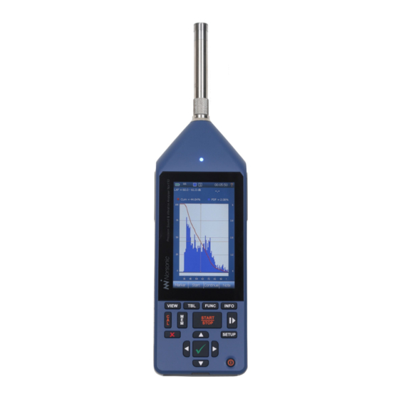
Page 19: Taking A Closer Look At The Instrument
The picture shows the Nor150 fitted with the standard preamplifier Nor1209 and the microphone Nor1225 mounted in sound channel one. The instrument is powered from an internal rechargeable Li-ion battery pack. -
Page 20: Switching On/Off
You may force the instrument to turn off by pressing the ON/OFF key for more than 5 seconds. Keyboard The Nor150 is mainly operated via the touch screen. There is however a dedicated backlit rubber keyboard used for operation of the main important functions such as power ON/OFF, measurement START/STOP, PAUSE and CALIBRATION. -
Page 21: Touch Sensitive Screen
The Start/Stop button (START/STOP): Starts Nor150 uses the latest technology for touch sensitive a measurement or Stops an ongoing displays. The capacitive touch technology eliminates measurement. - Page 22 Chapter 2 Taking a closer look at Nor150 Please note that the use of the backlight makes a significant impact on the power consumption. Start/Stop Pause/ Use the measurement control ( Continue ) in the touch sensitive display when you measure low noise levels.
-
Page 23: The Main Status Led
Norsonic Nor150 Instruction Manual The Main Status LED The multi-colour LED above the display indicates several operating states. Red colour indicates some type of error condition (like overload) while green colour is for positive information. State Color Behavior Description Startup/Booting... -
Page 24: Input And Output Connectors
Chapter 2 Taking a closer look at Nor150 Input and output connectors Several sockets are located behind the rubber cover on the bottom side of the instrument. Input channel 1 is located at the top of the instrument. This is the “default” channel and is the channel used LAN socket for most sound measurements. -
Page 25: On The Use Of The Internal Battery Vs. External Dc
Instruction Manual On the use of the internal battery vs. external DC The Nor150 comes with an internal Li-ion battery pack (Nor150/Battery) using the latest available charging technology. The battery pack is a so called smart battery where a built-in microprocessor holds all information about the power use and charging. -
Page 26: If Power Fails
DSP work load and thereby the power consumption. Optimising the measurement settings will The Nor150 has a built in power saving feature that also help on the power consumption. turns down the backlight and eventually switch itself off if left unattended in ready mode (I.e the instrument... -
Page 27: Optional Extensions
Instruction Manual Optional extensions Software maintenance The Nor150 comes with an extensive set of functions Norsonic provide regular firmware updates with new available in its basic version. Many other functions are features and bug fixes. By carefully listening to our available as optional extensions. -
Page 28: Your First Measurement
Assemble the instrument if it is not already done. can make your own and save them for later use. See “Application Selection Menu - Predefined Setups” on Turn on the Nor150 page 72“. and wait for the start-up sequence to terminate. If needed connect the mains adapter Nor345A. -
Page 29: Saving The Measurement To The Memory
Nor150 on a tripod. A mounting hole at the rear side of this manual. the instrument with a standard camera thread is used. -
Page 30: The Measurement Functions Available
Chapter 4 The measurement functions available The measurement functions available What is a Function? In the Nor150 the term is used to denote the combination of RMS (or Peak) detection with certain time constants (when applicable) and certain spectral weighting functions involving measurement duration whenever relevant. - Page 31 Function cube. So far we have yet to mention statistics. In the Nor150 statistics are either based on SPL using a user defined Figure 4.2 - The Function cube expresses a three-dimensional time constant or Leq.
- Page 32 Chapter 4 The measurement functions available Global measurement values are a single set Three time profiles are available, Profile A, Profile B and measurement values describing entire Profile Moving. Profile A is the main profile from where measurement. Such as L etc.
- Page 33 Norsonic Nor150 Instruction Manual The time profile resolution span is from 5 ms (10 ms in There is no limit to the of number weighting network dual channel mode) to 24 hours. To avoid overloading functions (A, C and Z), only the multispectrum functions.
- Page 34 Chapter 4 The measurement functions available The term Multispectrum is octave or third octave values acquired in the time profile. One spectrum is measured per profile period. This requires a relatively high amount of calculation power due to the amount of data calculated.
-
Page 35: Chapter 5 Setting Up The Analyser
If a specific set up is selected in the applications The organisation of the display selection screen, the associated functions and views After the Nor150 is turned on, the applications will also be loaded. selection screen appears (Figure 5.1). If you just pass The display (Figure 5.2) is divided in three main sections. -
Page 36: The Status Bar
Chapter 5 Setting up the analyser The status bar Status bar The status bar at the top of the display provides useful information about the instrument and the on-going measurement. The status bar Measurement picture 1 Battery gauge 2 Overload indication 3 Measurement status –... -
Page 37: Symbol # 2; Overload Indication
Norsonic Nor150 Instruction Manual Symbol # 2; Overload indication Symbol # 4, Application mode No overload Environmental Instantaneous overload. The symbol will turn to yellow after the overload disappear if a Building acoustics measurement is running. The LED on the front will also turn to red during an overload. -
Page 38: The Measurement Picture
Chapter 5 Setting up the analyser Pause an ongoing measurement and The softkey bar may have more function in other remove the paused values from the overall modes (Building Acoustic and Sound intensity measurement. Time profile is continuing, application). These softkeys are described in the but a pause marker is inserted in the time chapters describing these applications. -
Page 39: On-Screen Menus
Norsonic Nor150 Instruction Manual On-screen menus Each graphical view has an associated numerical table available. Just push the TBL button to access it. Context sensitive menus (Figure 5.3) are available when needed. They give access to several of the Up to four different views can be configured. Each view parameters that decide the look and feel of the view can either be a single or dual type. -
Page 40: Activate And Deactivate The Result Displays
Chapter 5 Setting up the analyser Activate and deactivate the result displays On-screen menus: If the display is split in two halves you can tap on any of SPL Live Selecting SPL Live will update the the display parts to set it active (Figure 5.4). The other SPL values in the L(f) view also after half then turns inactive (greyish). -
Page 41: Cursor Handling
Norsonic Nor150 Instruction Manual Cursor handling The main menu system - an As discussed in the previous chapter, the cursor will overview move in all display views if they are “linked”. This is The main menu appears when pushing the SETUP key useful if you want to move in the time domain and on the front panel (Figure 5.5). -
Page 42: On/Off/Available/Disabled Indication
Chapter 5 Setting up the analyser On/Off/Available/Disabled indication Your transducers, microphones and Input In most menus there are indications whether something preamplifiers are specified and is selected or not (Figure 5.6). The green tick means connected to the analyser in the that the function is selected and the red X means that Input menu. -
Page 43: Selecting The Different Views And The Parameters To Display
Instruction Manual Selecting the different views and the parameters to display Nor150 offer four different views that you can customize. Available views are You may rotate between the active views using the VIEW SLM - Sound level meter display, only showing global button. - Page 44 Chapter 6 Selecting the different views and the parameters to display L(t) (landscape) (Figure 6.3) – same as Figure 6.2, but only available as landscape (wide) in single frame mode. I.e. The graphical display is turned 90 degrees. Above the L/t graph is an additional graph that shows the entire L/t trace.
- Page 45 Norsonic Nor150 Instruction Manual FFT - Displays the FFT spectra (Figure 6.8). Available as portrait in single and dual frame mode. FF T (landscape) Displays the FF T spectra as landscape (Figure 6.9). Only available as single frame view. NOTE! Building Acoustic and Sound Intensity mode offers other views than described here.
-
Page 46: Function Selection - Selecting The Measurement Parameters
Chapter 6 Selecting the different views and the parameters to display Push the SETUP key and then the to gain access Views to the View setup menu (Figure 6.10). Each view has two menu points which can be turned on or off. Simply turn on one, two or none to set the current view to a single, dual or off. - Page 47 Norsonic Nor150 Instruction Manual - Figure 6.11 Function setup Selects how many parameters Max Functions in View you like to display simultaneously. Up to three parameters may be (Figure 6.12) displayed simultaneously. Select one if you need good readability, two or three if you want more...
- Page 48 Chapter 6 Selecting the different views and the parameters to display - Figure 6.12 Select Function setup Selecting a Function access a submenu where you select measurement parameter type, Select Function (Figure 6.12) colour, drawing order and shape. See separate description. Already selected parameters may be turned on/off or modified.
-
Page 49: Spl Live In Ended Mode
Norsonic Nor150 Instruction Manual SPL Live in ended mode Numerical tables It is possible to select live SPL update of the L(f) – Level Each graphical display has a numerical table as an alternative. Use the TBL button to switch between vs frequency display after a measurement is finished. -
Page 50: Input Selection Menu
You may also add new transducers or modify existing transducers or access the calibration menu. The Nor150 may be fitted with two sound channels (optional). In the example in Figure 7.1, only Sound Channel 1 active. -
Page 51: The Sound Channel 1 Or 2 Menu
Norsonic Nor150 Instruction Manual Line and Vibration sensor The Sound channel 1 or 2 menu No corrections available. The Sensor button accesses a list of available sensors (Figure 7.3). Adding, removing or modifying a sensor Microphones cannot be done from the list offered here. This is When turned on, a frequency correction Random incident. -
Page 52: Outdoor Microphones
Chapter 7 Input Selection Menu Outdoor microphones If you tap on one of the fields in this case 1209&1225 If any of the outdoor microphones Nor1214, Nor1216, a submenu with all the relevant parameters for this transducer will be available (Figure 7.5). Several are Nor1217 or Nor1218 is selected, the corrections above will disappear and be replaced by the two following locked and cannot be edited. - Page 53 Norsonic Nor150 Instruction Manual The name of the sensor. Give each of your microphone / preamplifier Name combinations a name so they are easy to recognize. Name is not a locked field and may be edited. Opens up a L(t) graph which holds historical data of the calibration. Move Calibration history cursor to obtain information about previous calibrations.
-
Page 54: Adding A New Sensor
Here you add preamplifier gain. Normally the preamplifier attenuates the signal from the microphone due to its input capacitance. Hence you should enter a negative number. Negative gain=attenuation. For Norsonic preamplifiers this value is in the range of -0.2 to -0.5 dB. Set this to 0 dB if you don’t know the gain. -
Page 55: Preamplifier Selection
GRAS 40HL polarization voltage. If polarization voltage is required which may be directly connected to the Nor150. You then a “traditional” preamplifier with a multi-pin (7 pin need to specify this as a Non predefined sensor. This Lemo) socket is needed. -
Page 56: Calibrating The Instrument - Field Check
Other correction may apply for different types of operation as it is a device of adjusting the sensitivity of microphones. sound measuring instruments. Do as follows: The Nor150 is calibrated by clicking the CAL button or in the SETUP > > > menu. - Page 57 (Figure 8.1). Calibration calibration. The level is displayed in the L(t) trace in Nor150 offers two different ways to perform an the calibration menu. New values are set with the √. acoustical calibration, or Auto. The third...
-
Page 58: Calibrating A Vibration Sensor
The Nor150 has a buillt-in Mic. Check feature that allows this (also called SysCheck). - Page 59 Hence, a ¼” microphone will return a much lower signal level than 90 dB. The Mic. Check feature works also with the Norsonic Dehumidifier Nor1284 and Nor1285 mounted. 3. It is recommended to not adjust the sensitivity level.
-
Page 60: Measurement Setup Menu
Chapter 9 Measurement Setup Menu Measurement Setup Menu There are a large number of parameters that can be selected for a measurement. Use the SETUP key and then the Measurement selection to configure the various measurement parameters (Figure 9.1). Global and Profile Time opens up a sub menu where you set the following;... -
Page 61: High-Pass Input Filter
Norsonic Nor150 Instruction Manual The instrument is capable of measure all three available time weighting filters A, C and Z in parallel. You may also define which of the filters that shall be used in idle mode (readymode). Turns the real time 1/1 or 1/3 octave band Filter On/Off. - Page 62 16 bit if you want to replay the audio recording on the instrument itself. All formats are however supported in NorReview. The Nor150 fitted with option 1 offers a support Camera. for various camera types. In this menu you configure the Percentiles (%).
-
Page 63: Weather Station
Norsonic Nor150 Instruction Manual Weather Station • Repeat, which causes the instrument to store the acquired data and then restart immediately Turns the weater station logging on/off. and make another measurement using the same A submenu (figure 9.3) is avalable where you can select measurement setup and duration. -
Page 64: Chapter 10 Fft
Chapter 10 Making a measurement Introduction The FFT calculation is performed in parallel with 1/1 or When the FFT option 13 is installed, the instrument can 1/3 octave band analysis and the weighting networks make a narrow-band frequency analysis of the input enabled. -
Page 65: Calibration
Norsonic Nor150 Instruction Manual The frequency range may be zoomed or compressed. The compression factor is adjusted in a power of 2 sequence using the context sensitive menu shown in figure 10.2. If the display is compressed, more spectral lines are displayed as one line. The cursor value will show the maximum value for all the lines represented by the cursor position. -
Page 66: Trigger Selection Menu
It is however, often required to start a Figure 11.1 Figure 11.2 measurement based on other criteria’s than to push the start button. The Nor150 has a variety of choices found in the menu (Figure 11.2). Global Measurement Independent on the selections made in the Global Trigger menu, the START button must be pressed to activate the setting. - Page 67 A delayed start of 0 - to 180 sec is available. Clock Trigger The measurement start is controlled by the real time clock. The measurement will start once the real time clock in the Nor150 passes the next full hour. On Next Full Hour External Trigger The measurement will start once the external trigger is activated.
- Page 68 Chapter 11 Trigger Selection Menu Level Below The measurement will start once the level is below the set trigger level. In addition to the level, the measurement parameter can also be specifi ed. Level Above The measurement will start once the level is above the set trigger level. In addition to the level, the measurement parameter can also be specifi ed.
-
Page 69: The Event Trigger
Norsonic Nor150 Instruction Manual The Event Trigger An event is a significant change in the sound level for more than a minimum period of time. The amount of level change required is predefined by you by setting a threshold level. Hence, the purpose of the event triggers is to start an action based on the event. - Page 70 Chapter 11 Trigger Selection Menu Each of the five event triggers can be configured independently. The main purpose of offering five instead of one trigger is to associate different trigger levels during a certain time period. Each of the five triggers is connected to the real time clock.
- Page 71 This is the minimum duration the event trigger condition See separate chapter for how to configure an external is not fulfilled. camera to work with the Nor150. Time Between events This is the minimum time between events. An event will be rejected if it occurs before the minimum time is reached.
-
Page 72: Working With Markers
Chapter 12 Working with markers Working with Markers Setting up Markers - the Marker Setup menu Have you ever made a measurement where you later found out that you desperately need to identify the cause of the level? Recording the audio may be one answer, but for attended measurement it may be more convenient to add markers to the measurement. -
Page 73: System Specified Markers
Norsonic Nor150 Instruction Manual Each marker may also start an action. The following A red single marker labelled “C” for continues Continue: actions can be assigned to a marker. is inserted in the time profile if you terminate an ongoing... -
Page 74: Adding A Marker To An Ongoing Measurement
Chapter 12 Working with markers Adding a marker to an ongoing Working with markers - measurement post processing An on-screen selection with the available markers Once a measurement is elapsed, or recalled from Marker appears in the measurement picture when the memory, you may edit, delete, move or jump between button is activated. -
Page 75: Recording The Sound - Audio Record And Replay
Instruction Manual Recording the sound - Audio record and replay The Nor150 allows storing the sound signal itself obtained by the microphone if the appropriate option 4 is installed. The most common application is for identifi cation purposes (by listening to the sound signal). -
Page 76: Making A Recording
Chapter 13 Recording the sound The instrument has a large dynamic range – Manually by connecting the audio recording action to Gain. exceeding 120 dB. This means that if you try to play a Marker. back the recorded sound after having transferred Manually using the remote hand switch Nor263 the files to your PC, you will –... -
Page 77: Listening - Replaying An Audio Recording
Norsonic Nor150 Norsonic Nor150 Instruction Manual Instruction Manual All recordings are made in a standardized WAV-format If you want to make an automatic recording lasting which allows most media-players to play the recorded for the whole measurement, set a very low threshold file if they are transferred to a PC. -
Page 78: Chapter 14 Camera
Chapter 14 Camera Camera The Nor150 fi tted with option 1 offers support for various camera types. External camera(s) is confi gured in the SETUP > Measurement > Camera menu. The internal camera is not affected by the setting in this menu. -
Page 79: Ip Camera
5. The pictures are available in the on screen remote control features offered by the NorRemote app menu on the Nor150 after the measurement is fi nish. described in the previous section. We support the Axis The pictures follow the measurement data and can... -
Page 80: Chapter 15 Voice And Text Notes
Instrument Analog Output Headset prior to the measurement. Norsonic headset Nor4584 is suitable for this use. Most other type of headset with microphone and a 3,5 mm jack plug is also suitable. Retrieving text and voice notes. ou may read the text notes by placing the cursor on... - Page 81 However, this feature does not connect the notes HINT! Nor150 fitted with the enhanced environmental to the applicable event marker. If this is needed, push option (option 11) offers a neat solution for setting...
-
Page 82: Pausing And Resuming A Measurement
Chapter 16 Pausing and resuming a measurement Pausing and resuming a measurement Extensive pause and continue functions are available. When paused, the instrument will produce and display the time profile for the last 20 seconds of the measurement. The time cursor can then be moved backwards in one seconds step to remove the unwanted noise and resumed. -
Page 83: The Difference Between A "Pause" And A "Hold" Function
Figure 16.3 more measured values (max and peak) while the measurement still runs. In the Nor150 this type of function is not needed since every level-display can have several parameters displayed simultaneously. It is up to the operator which results to display at any time. -
Page 84: Storing A Measurement - Memory Organising Menu
Chapter 17 Storing a measurement Storing a measurement - Memory Organising Menu The MEM button is used to retrieve a stored measurement. You may also via a context sensitive menu, rename, move, delete and recall information from a single measurement. Similar, you may move, delete or rename a directory. -
Page 85: File Name
Norsonic Nor150 Norsonic Nor150 Instruction Manual Instruction Manual File name It is important to know the different storage modes The instrument offers a sophisticated file naming and what features they offer. system with a variety of options. The configuration of the storage mode is set in the You may either enter the file name manually when SETUP >... -
Page 86: Unique Measurement Identifier
Chapter 17 Storing a measurement There is a limitation of 1000 measurements if you use the same letters in the first 4 letters of a filename. For automatic measurement names (timestamp), there will be a limit of 1000 measurements per year on the same SD card. -
Page 87: Rename, Delete, Move
Norsonic Nor150 Norsonic Nor150 Instruction Manual Instruction Manual Rename, Delete, Move Save Debug Log A file or directory may be renamed, deleted or moved. Although every effort is done to ensure a stable and bug These features are offered in context sensitive menu free software it might happened that you experience menu or pushing the MEM button. -
Page 88: Application Selection Menu - Predefined Setups
Chapter 18 Application Selection Menu - Predefined Setups Application Selection Menu - Predefined Setups is normally the first menu that There are three different types of Setups; Instrument Application menu appears after the instrument is powered on and the boot mode, indicated by large icons. -
Page 89: Creating A User Defined Setup
Norsonic Nor150 Instruction Manual Creating a user defined setup Selecting a setup, except from “last used” will open a “measurement info” picture (Figure 18.2) which holds A user defined setup is stored via SETUP > Memory the most important information about this setup. At the >... -
Page 90: Signal Generator (Optional)
Chapter 19 Signal Generator Signal Generator (Optional) The signal generator option facilitates the use of the instrument for various applications. The main use is sound insulation and reverberation time measurements White, pink, sine and band-pass filtered noise types are available. The noise excitation can also be synchronized with the measurement sequence. -
Page 91: Chapter 20 Building Acoustic
Instruction Manual Building Acoustic Introduction When equipped with the required program option(s), Nor150 is well suited for measurement of building acoustics in the form of measuring reverberation time and sound insulation. The Building Acoustics mode allows measurement of building acoustics parameters according to the ISO 16283 series of International Standards as well as National Standards like DIN, BS, SS, SIA, etc. -
Page 92: Measurement Mode
Chapter 20 Building Acoustic Measurement Mode The Measurement mode appears after starting the instrument or changing into BA mode. This is the mode where measurements are taken, contrary to Project Mode where the accepted measurements and calculated results are presented. The soft key in the lower left corner lets you switch between these two display modes. -
Page 93: Display Views In Measurement Mode
Norsonic Nor150 Instruction Manual Display views in Measurement Mode The Measurement mode has a fixed set of display views. Unlike the Environmental Mode these views cannot be modified and therefore the setup menu item “Views” is not available. While a single channel instrument will have two views, a dual channel instrument will offer four different views. -
Page 94: Single-Channel Views
Chapter 20 Building Acoustic Single-Channel views Figure 20.8 shows a split display with a L(f) on top of a L(t) graph. Figure 20.9 is a full screen L(f) graph. There is a header line showing the selected standard, the measurement type (Level, BGN, RT) and the source position (#A...#D). -
Page 95: Setup
Norsonic Nor150 Instruction Manual Setup The automatic Y-axis range can be activated individually for Level, Reverberation and Rating graphs. There are different available in order Setup menus to adjust the Building Acoustics parameters (Figure 20.12). Push the SETUP button and select the NOTE! Auto Range does not work while in idle or appropriate sub-menus.. -
Page 96: Level - Setup (Figure 20.16)
1/3- and 1/1-octave measurements. Please note that for all Reverberation - Setup (Figure 20.18) but one currently supported building acoustics testing Standards in the Nor150 system, only the • enables the user to switch between 1/3- and Filter 1/3-octaves are selectable. -
Page 97: Rating - Setup
Norsonic Nor150 Instruction Manual • is setting the maximum time, but the calculation ranges are individual Max expected RT reverberation time to be measured. In reality, this for each function. EDT starts at 0 dB below the setting controls the period length of each sample excitation level and end -10 dB below. -
Page 98: Source (Figure 20.21)
Chapter 20 Building Acoustic Source (Figure 20.21) • Volume is the actual volume of the source Volume room given in m . For the source room, this value is calculated based on entered values for width, height and length of the actual room. If the room is non-square, and the fi nal volume is known, the user may simply enter ‘1’... -
Page 99: Test Specimen
Norsonic Nor150 Instruction Manual Test Specimen Various parameters (Figure 20.25) • (Figure 20.23) is the size of the common • is used for activating corrections Area BGN Corrections partition in square meters. This value is calculated to the measured values in the fi nal calculations. -
Page 100: Memory - Setup (Figure 20.27)
START/STOP key or the Start soft key to run the your measurement project upon acceptance. You measurement. The Nor150 will now automatically will be prompted for a fi le name at fi rst use. activate the noise generator. • is used to store your Save Measurement Setup as own setup. - Page 101 Norsonic Nor150 Instruction Manual Single-Channel views while measuring: Figure 20.28 Figure 20.29 Dual-Channel Views 1 - 4 while measuring: Figure 20.30 Figure 20.31 Figure 20.32 Figure 20.33...
-
Page 102: Making The Background Noise Measurements
Chapter 20 Building Acoustic When the pre-set measurement duration is ended, It is a good idea to save your work frequently. We Stop or the key is pushed the display changes its advise you to store your measurement project each appearance. -
Page 103: Making The Reverberation Time Measurements
(Tip: use the FUNC key). Push either the large START/STOP key or the Start soft key to run the measurement. If the excitation type is Noise, the Nor150 will now automatically activate the noise generator. In case of Impulse excitation, the Nor150 will trigger on an impulse signal. -
Page 104: Project Mode
Chapter 20 Building Acoustic Display views in Project Mode It is a good idea to save your work frequently. We The Project Mode has a fixed set of 4 display views. advise you to store your measurement project each Select the desired measurement function with the time you have accepted a measurement. - Page 105 Norsonic Nor150 Instruction Manual Rating Reverberation Receiving Source Background Figure 20.41 Within the Project Mode there is a distinction between the views presenting the rating results (Rating) and the views presenting the accepted measurements (Reverberation, Receiving, Source and Background). Report...
-
Page 106: Rating Views 1 - 4
Chapter 20 Building Acoustic Rating views 1 - 4 Figure 20.44 Figure 20.45 Figure 20.46 Figure 20.47 Rating View-1 Figure 20.44 presents the calculated sound insulation together with the single number index according to the selected standard in a dual frame. The upper frame shows the results graphically while the lower frame contains the numerical values. -
Page 107: Rating View-2
Norsonic Nor150 Instruction Manual Rating View-2 Rating View-4 Figure 20.45 is a plain numerical table to present the This view (Figure 20.47) contains information about single number index along with the spectrum adaption the influence of the background noise to the receiving terms. -
Page 108: Measurements Views 1 - 4
Chapter 20 Building Acoustic • L2 or L2’: average sound pressure level in the The views for the reverberation time and the views for receiving room (L2’ means it’s corrected for the sound pressure levels are in principle the same. It background noise) is only the unit and the scaling that is different. -
Page 109: View 1- 4 For Reverberation Time Measurements
Norsonic Nor150 Instruction Manual View 1- 4 for reverberation time measurements Figure 20.52 Figure 20.53 Figure 20.54 Figure 20.55 View 1 - 4 for receiving room measurements Figure 20.56 Figure 20.57 Figure 20.58 Figure 20.59... -
Page 110: Measurement View-1
Chapter 20 Building Acoustic Measurement View-1 • SD: Standard Deviation of the average View-1 presents average accepted • N: Number of measurements included in the average measurements in a graphical and numerical way. Screen shot of Receiving average limited to source It covers all microphone and source positions. -
Page 111: Measurement View-2
Norsonic Nor150 Instruction Manual Measurement View-2 View-2 displays average included measurements graphically and in a table. This is helpful to see how the different microphone positions vary. If available, use the # soft key to display the average of a specific source position #A…#D and the measurements... -
Page 112: Measurement View-3
Chapter 20 Building Acoustic Measurement View-3 Screen shot (Figure 20.62) of Receiving room total (All) average and its measurements View-3 displays the average and just one of its measurements graphically and in a table. • Avg: Energetic (Level) or linear (Reverberation) average of accepted measurements. -
Page 113: Measurement View-4
Norsonic Nor150 Instruction Manual Measurement View-4 View-4 presents the selected microphone position (not the average!) from the previous view as a Level vs frequency L(f) and Level vs time (L(t) graph. Use the arrow keys on the keyboard to select a different microphone position. -
Page 114: Exclude Measurement Positions
Chapter 20 Building Acoustic Exclude measurement positions To exclude individual measurement positions data from the calculated average, use the soft key Exclude available in the Measurement View-3 (Figure 20.64) and Measurement View-4 (Figure 20.65). This position will then be marked with an both in the Measurement Views (Figure 20.69) and in the Project View (Figure 20.70). -
Page 115: Start A New Project
Norsonic Nor150 Instruction Manual Figure 20.76 Figure 20.75 Figure 20.73 Figure 20.74 Start a new project To start a new project pushing the button to close the current measurement project and start a new one. You may be asked to save the current data (Figure 20.75). -
Page 116: Chapter 21 Sound Intensity
, sound power, and FpI. The range of available functions depends on the selected measurement standard. The Nor150 will, in combination with the Nor1290 probe and the Nor1294 phase verifi cation coupler, ensure that most intensity measurements may be performed with a single 12 mm spacer. -
Page 117: Setting Up The Instrument For Intensity
Instruction Manual Setting up the instrument for intensity The Nor150 may utilize a wide range of probes, both pre- polarized and 200 V polarized microphones in different configurations. However, the highest performance and ease of use is achieved using the Nor1290 probe kit. - Page 118 To use the probe handle, connect the probe at the top of the rod, then add an extension cable between the bottom end of the rod and the Nor150. The optional smartphone will provide the same view as the Nor150 itself, offering a one-hand operation of intensity measurements.
-
Page 119: Probe Dismantling
Probe dismantling Transducer setup To do probe calibration and verification, it is necessary For customers buying the Nor150 with the Nor1290 to partly dismantle the probe. Open the spacer probe kit, all settings are predefined from the factory. adjustment knob (see Figure 21.3) and pull the Setting up the probe is then easily done: microphones apart as shown in Figure 21.6. - Page 120 Chapter 21 Sound Intensity Figure 21.7 shows the menu. Channel Microphone capsule Measurand: “Pressure in air ref 20e-6 Pa” If the kit is delivered separately, the parameters of specified cal. chart Type: the transducers and the probe must be set up before as specified in the cal.
-
Page 121: Connecting A Smartphone
Insert probe microphone A into a sound calibrator such as a Nor1251. Open the calibration menu on Sound Intensity mode supports the NorVirtual the Nor150 by pressing CAL followed by a tap on smartphone app. Please see NorVirtual page 149 . Calibration. The... -
Page 122: Phase Correction
Nor1294 into CLOSED position as shown in Figure 21.13. Connect the Nor1294 mini-jack into the headset output of the Nor150. Then press the START soft key to initiate the correction process. A progress bar will keep you updated, and the calibration is fully automatic. - Page 123 Norsonic Nor150 Instruction Manual When the correction process is done, the instrument The maximum pressure-intensity residual spectrum will show the pressure-intensity residual spectrum is determined from the inheritent uncertainty in the measured with corrections applied. The minimum correction procedure and the physical properties requirement defined in IEC 61043:1993 will be shown of the Nor1294 coupler.
- Page 124 Chapter 21 Sound Intensity NOTE: If the correction process returns lower values HINT: The instrument will warn you if it detects too low sound pressure during the calibration process. than expected, the reason might be high pressures This will typically happen if the Nor1294 is left in applied to the microphones before phase correction.
-
Page 125: Verification Procedure
“Calibration and phase correction” on page 105. The residual spectrum data is stored in the Nor150 along with time and date. Thus, it is possible to look at the previous calibration or verification, and track the history. -
Page 126: Configuring An Intensity Measurement
21.19). Or by hitting the key in total scop view. Select Show Setup Shortcut to show the setup in the The Nor150 intensity mode offers different setups menu. Applications when pressing the SETUP key, followed by a tap on... -
Page 127: Probe And Environment Parameters
Instruction Manual Probe and environment parameters Before a measurement is started, the probe must be configured. For the Nor150 in combination with the Nor1290 kit, the 12 mm spacer is the correct choice for most measurement applications. Go to the channel menu by pressing CAL (Figure 21.23). - Page 128 Chapter 21 Sound Intensity Back Right Segment in surface Left Surface the Front surface Left Front Figure 21.25 - The cuboid is divided into surfaces, and each Figure 21.26 - Intensity measurement with fi xed probe surface is built up of one or more segments. positions.
- Page 129 Figure 21.29 - The coordinates defining the cuboid surface. Figure 21.28 - The surface type selection. When entering the surface dimensions, the Nor150 will divide the surfaces (e.g. left) into several segments, such that no segments will have an area of more than 1 .
- Page 130 Chapter 21 Sound Intensity Figure 21.31 shows the settings found inside a surface created when a cuboid surface type is selected. The menu contains settings for number of rows and columns. Changing either of these will make the instrument recalculate the segment dimensions based on the surface dimensions.
-
Page 131: Measurement Settings
This is useful Norsonic recommends to always set the Filter range both for analysis of weighted intensity and sound power to span from 20 Hz to 20 kHz. - Page 132 Figure 21.33. The notations Selecting a standard “horizontal” and “vertical” is just a way of conveniently The sound intensity mode in the Nor150 will provide remembering scanning directions. The user may of different measurement functions based on the course use any preference in orientation while scanning.
- Page 133 Norsonic Nor150 Instruction Manual Warning for current segment Current segment Warning for cursor position Current surface Negative values in opposite direction Warnings for Sound each band pressure level Toggle between intensity and power Sound intensity with direction Open the Frequency range...
-
Page 134: Navigating The Sound Intensity Mode
Introducing the surface scopes As discussed in “Defining a measurement surface” Figure 21.35 - Double-tap a surface or segment to open the on page 111 the Nor150 operates with the concept corresponding scope. will bring you up in the scope Back hierarchy. -
Page 135: The Views
Norsonic Nor150 Instruction Manual The views all. Red indicates that not all segments are completely measured. Green indicates that all segments are The instrument provides different views to represent completely measured. The bold black frame indicates data. The content inside the views will depend on the which segment or surface is currently selected. - Page 136 Chapter 21 Sound Intensity Figure 21.36 - Tap and Figure 21.37- Tap and Figure 21.38 - Scope view Figure 21.39 - Scope view drag up or down to hold somewhere on the for the total scope. for the surface scope. change the level limits.
-
Page 137: Errors And Warnings
Simple view is shown in Figure 21.43. Errors and warnings The Nor150 calculates field indicators and evaluates All data may also be presented in tabular format using criterions belonging to different standards in the the TBL key, as shown in Figure 21.44. - Page 138 Chapter 21 Sound Intensity In addition, a blue triangle indicates that a band is excluded: Warning for weighted sum frequency range (A/C/Z) Excluded band Negative intensity indication In the frequency spectrum view, the warnings are indicated with exclamation marks below the bar. Figure Cursor position warning 21.46 illustrates the warning indication.
-
Page 139: Saving And Loading Intensity Projects
The smartphone with NorVirtual App provides exactly the same features as the instrument by presenting the Figure 21.49 - Warning Figure 21.50 - same picture. See “Norsonic software” on page 155 panel shows warnings for Recommended action for the cursor position. Press a frequency band. -
Page 140: Measurement Configuration
Before the measurement is started, the environmental scans for each segment. These are denoted Horizontal parameters must be set up and the probe calibrated on the Nor150. If survey grade is desired, Vertical as described in “Probe and environment parameters” change the Accuracy setting to Survey. -
Page 141: Measuring
Norsonic Nor150 Instruction Manual Measuring Please make sure that the measurement is confi gured and set up as described in the previous section, including the calibration routine. The measurement surface may be marked to guide the orientation of the probe during a scan. Tape, or a thin rigid grid may be helpful. -
Page 142: Reviewing The Measurements
This graph shows the difference sound intensity. The indicators are presented in separate (∆) functions generated based on the two scans as views in the Nor150. Below is an overview of the data illustrated in Figure 21.57. presented in the different scopes. -
Page 143: Surface Scope
Norsonic Nor150 Instruction Manual Surface scope The surface scope presents data from all segments inside a surface scope. Thus, it functions as an intermediate total, simply to gain overview of the different surfaces and provide easier analysis of the source under test. -
Page 144: Total Scope
Chapter 21 Sound Intensity Scope view The second graph displays dynamic capability along Presents a graphical view of the total measurement with the field indicator FpI, the same way as for a surface. The total A-weighted data is shown, and segment. -
Page 145: Measurement Functions And Indicators
Norsonic Nor150 Instruction Manual Measurement functions and indicators Warning indicators Sound power measurement according to ISO 9614-2 uses Dynamic capability too low the intensity values to generate sound power levels for Triggered if the FpI exceeds the dynamic capability each individual segment, and summing these for both for a frequency band (FpI >... -
Page 146: Sound Power Using Iso 9614-1
Chapter 21 Sound Intensity Sound power using ISO 9614-1 Weighted sum range not complient The ISO 9614-1 standard differentiates from the Issued if Weighted sum freq. range is not set to exactly ISO 9614-2 by using fixed measurement positions 50 Hz to 6.3 kHz. instead of the scanning procedure. -
Page 147: Measurement Time
35 seconds, as seen in Figure 21.60. We recommend setting the to your desired value. The Global Time Nor150 will automatically stop a measurement when is reached. Global Time While measuring according to ISO 9614-1, it is also possible to measure and watch the measurement in short-term profiles. -
Page 148: Temporal Variability
The averages are evaluated in terms of standard deviation. Figure 21.61 - Temporal In the Nor150, this is implemented as a measurement Variability Section. separate from the rest. According to ISO 9614-1, one should choose a “typical”... -
Page 149: Measuring
HINT: The L(t) view will have a long profile time, and HINT: The Nor150 will warn you if the requirement accordingly few samples. The measurement will look of 10 positions are not fulfilled, as shown in Figure like the one in Figure 21.66 if only five averages is... - Page 150 Chapter 21 Sound Intensity Figure 21.64 - Tap and Figure 21.65 - The Figure 21.66 - Only Figure 21.67 - Regular hold a segment to make instrument will show you five periods of data. spectrum view accessible Press TABLE to show a by pressing VIEW.
-
Page 151: Main Measurement
The indicators are while waiting for accept. The next section will describe presented in separate views in the Nor150. Below is an how to review the results in detail. overview of the data presented in the different scopes. - Page 152 Chapter 21 Sound Intensity Segment scope The segment scope presents data for a single segment. Thus, no graphical surface (scope view) is available in this scope, and simple view is selected when tapping into a segment. Pressing VIEW toggles between the views described below.
- Page 153 Norsonic Nor150 Instruction Manual L(t) view This view presents the sound intensity and sound pressure as a function of time. Note that this is also a mirrored graph, with sound pressure mirrored up and down for reference. Press the up/down arrow keys to cycle through filter bands, and left/right to move the cursor.
-
Page 154: Total Scope
Chapter 21 Sound Intensity The last group is F3-F2 (F3 subtracted by F2), which is a measure for the extraneous intensity. The F3-F2 is equal to the one for Total Scope, presented in Figure 21.81. Total scope The total scope presents the total data generated from the sum and average of individual segments. - Page 155 Norsonic Nor150 Instruction Manual Figure 21.82 - Carefully Figure 21.83 - The Scope Figure 21.84 - Overview Figure 21.85 - Warnings note the Calculation Area View for Total. of all warnings are for each band in Total to ensure it matches the presented when the Scope.
- Page 156 Chapter 21 Sound Intensity Advanced view Six different spectrums are presented by toggling the FUNC key. The warning window is available for all spectrums by pressing the INFO key. Table representation is also available using the TBL key. The first function group shows sound power, sound intensity and sound pressure at the same time.
-
Page 157: Measurement Functions And Indicators
Norsonic Nor150 Instruction Manual Deduced measurement functions Lw – sound power, calculated for all scopes, referenced 1 pW. F1 – Temporal variability indicator, calculated for temporal variability measurements. Linear quantities. F2 – pressure-intensity indicator ( Leq – Ieq ), calculated for all scopes. - Page 158 Chapter 21 Sound Intensity Too short averaging time – Triggered if the Inadequate number of positions averaging time is less than the requirement for a Issued if N > C*F2, where N is the number of positions segment. and C is constant depedent on frequency and selected accuracy.
-
Page 159: Chapter 22 Instrument Specific Setup
Norsonic Nor150 Instruction Manual Instrument Specific Setup Digital and Analog I/O This menu (figure 22.1) holds all the setup related to the peripherals, power saving settings, language, clock, etc. Figure 22.2 Digital and Analog I/O Figure 22.1 menu. Instrument setup menu. -
Page 160: Digital Output
This menu manages the setting of analogue output 1210A or C. See “Microphone check” on page 40. found on the 15 pin I/O socket. The purpose is to – The line goes high when the Nor150 bypass the microphone signal from either channel 1 Remote controlled is controlled from another device. -
Page 161: Communication
Thus, never disconnect the dongle when the Nor150 is on. The available networks will be shown in the WLAN submenu. The system will automatically connect to the last connected network. -
Page 162: Security
NorRemote server (requires option 11, enhanced Noise Assessment Option). This program allows you to take full control of the Nor150 from an external device such as a PC, pad or smartphone. You should configure password to protect the unit from unauthorised use. - Page 163 • Correct address to the server. The default address is norcloud.norsonic.com . This address should The Nor150 stores all data locally on the SD card and normally not be changed unless you are connected will not erase this data before a set limit configured in to a local installation.
- Page 164 Chapter 22 Instrument Specific Setup List of status messages Status and error messages provided by the Nor150 when running in NorCloud mode. In case of an error, the green tick mark is replaced by an orange tick mark and a “reconnect now” button appears.
- Page 165 PC program that enables you to create a NorVirtual copy of the Nor150 including live update of the screen on your PC or smartphone. This feature is especially useful for seminars etc. It may also be used to remote control the instrument in a simple and easy way since it is a 1:1 copy of the instrument screen.
-
Page 166: Connection
Chapter 22 Instrument Specific Setup Connection: Limitations Phone and instrument must be connected with Wifi in The response when clicking and scrolling is slightly one of these ways: slower than using the instrument directly. The latency depends on the connection bandwidth and the •... -
Page 167: Instrument Name
48KHz – 24-bit resolution. The synchronization requires that cable type Nor4633 is connected to each of the Nor150’s 15 pin I/O connector. One unit is set as master, the others as slave (Cf figure Figure 22.13 Figure 22.14... -
Page 168: Language
Chapter 22 Instrument Specific Setup labelled “Out”. Connect the “out” from the master unit to the first slave units cable labelled “in”. Then connect the “out” from the first slave unit to the next slave units “in” and so on. The out signal is found on DO - 3 (pin3) and the in signal is on DI-3 (pin 10) After the connection is completed and proper master... -
Page 169: Number Format
These instruments are normally to the update of the operating system. Connect the USB fitted with a “seal” option preventing unauthorised stick to the Nor150 USB port while the instrument is software updates. turned off. Turn on the instrument. The Instrument will... -
Page 170: The Software License System
Hence, License.txt. Connect the memory stick to the USB port updating to a non-approved version is not legal. In on the Nor150. Install the new license code in SETUP > this case contact your local Norsonic sales office. >... -
Page 171: Chapter 23 Norsonic Software
NorVirtual App allows the user to remote for calculations, report generation and for replaying of control the Nor150. The app is an image of the display audio recordings and marker management. The use of and keyboard of the instrument and allows the user this program is not covered by this manual. -
Page 172: Chapter 24 Technical Specifications
The instrument also conforms to a number of national standards such as: DIN 45657 (2013-02-06). Firmware version The specifications in this manual are valid for a Nor150 with software version 3.0 and above. The version number can be found using the SETUP >... -
Page 173: Analog Inputs
Nor1290 and some other probes is selected Input connector GND - signal reference 7 pin LEMO connector for Norsonic microphone Polarization voltage – selectable: 0±1V, 200±1V systems. (LEMO ECG.1B.307.CLL) or adjustable 70 to 74 V short-circuit current <1mA, impedance: 2 MOhm... -
Page 174: High-Pass Input Filter
Chapter 24 Technical specifications High-pass input filter Microphone The microphone input section is equipped with an analog high-pass filter to reduce noise from wind or Nor1225 data other sources with frequencies in the lower end of the Microphone type: Free field microphone frequency range. -
Page 175: Nor1209 Data
Power supply: ±14 V(1 mA) to ± 60 V (2,8 mA). The the sound level meter, or connected via a suitable cable. Nor150 supply ± 15 V to the preamplifier. Alternative Power supply: The preamplifier is equipped with a system check Single: 28 V (1mA) to 120 V (2,8 mA) facility. -
Page 176: Acoustical Data
The capacitance will increase proportionally with the length of the cable. A Reference direction: typical value for microphone cables from Norsonic is The microphone reference direction is from the 120 pF per metre. Hence, a cable with length 100 m, microphone and along the axis of rotational symmetry will load the output with a capacitance of 12 nF. -
Page 177: Detailed Table For Level Corrections According To Iec 62585
Norsonic Nor150 Instruction Manual Detailed table for level corrections according to IEC 62585 63,1 0,00 0,00 0,05 0,00 0,05 0,00 0,00 0,05 79,4 0,00 0,00 0,05 0,00 0,05 0,00 0,00 0,05 100,0 0,00 0,00 0,05 0,00 0,05 0,00 0,00 0,05... - Page 178 Chapter 24 Technical specifications 1995,3 -0,06 0,32 0,13 -0,31 0,10 0,48 0,08 0,30 2113,5 -0,07 0,34 0,13 -0,01 0,10 0,51 0,09 0,30 2238,7 -0,08 0,36 0,13 0,13 0,10 0,57 0,14 0,30 2371,4 -0,09 0,42 0,14 0,11 0,10 0,61 0,16 0,30 2,5 k 2511,9 -0,10...
- Page 179 Norsonic Nor150 Instruction Manual 8414,0 0,21 3,78 0,30 0,08 0,15 0,09 0,49 0,40 8912,5 0,25 4,17 0,30 -0,07 0,15 0,14 0,62 0,40 9440,6 0,38 4,59 0,30 -0,13 0,15 -0,08 0,48 0,40 10 k 10000,0 0,48 5,01 0,30 0,25 0,20 -0,27...
- Page 180 Chapter 24 Technical specifications Case correction: Correction to be added to the free- field response of the microphone to obtain the free-field response of the sound level meter when the standard microphone system is mounted in the front of the instrument (Sound channel 1).
-
Page 181: Directional Response - Horizontal
Norsonic Nor150 Instruction Manual Directional response – Horizontal Maximum absolute value of the difference between displayed sound levels at any two sound-incidence angles within ±ө degrees from reference direction. θ = ± 30º 10 k 100 k Frequency [Hz] θ = ± 90º... - Page 182 Chapter 24 Technical specifications Directional response -5 dB 5 dB -5 dB 5 dB 1,6 kHz 630 Hz 2 kHz 800 Hz 2,5 kHz 1 kHz 3,15 kHz 1,25 kHz ϕ ϕ -5 dB 5 dB -5 dB 5 dB 4 kHz 10 kHz 5 kHz...
-
Page 183: Directional Response - Vertical
Norsonic Nor150 Instruction Manual Directional response - Vertical The directional response of the complete instrument is measured in the horizontal direction (sideways, with the display facing upwards). Zero degrees are in the direction of the microphone. θ = ± 30º... - Page 184 Chapter 24 Technical specifications Directional response -5 dB 5 dB -5 dB 5 dB 630 Hz 1,6 kHz 2 kHz 800 Hz 2,5 kHz 1 kHz 3,15 kHz 1,25 kHz ϕ ϕ -5 dB 5 dB -5 dB 5 dB 4 kHz 10 kHz 5 kHz...
-
Page 185: Directional Response - Horizontal With Wind Screen
Norsonic Nor150 Instruction Manual Directional response – Horizontal with Wind Screen The graphs and plots below show the directional response for the complete sound level meter Nor150 with preamplifier Nor1209, microphone Nor1225 and windscreen Nor1451. θ = ± 30º 10 k... - Page 186 Chapter 24 Technical specifications Directional response -5 dB 5 dB -5 dB 5 dB 630 Hz 1,6 kHz 800 Hz 2 kHz 1 kHz 2,5 kHz 1,25 kHz 3,15 kHz ϕ ϕ -5 dB 5 dB -5 dB 5 dB 4 kHz 10 kHz 5 kHz...
-
Page 187: Directional Response - Vertical With Wind Screen
Norsonic Nor150 Instruction Manual Directional response – Vertical with Wind Screen The graphs and plots below show the directional response for the complete sound level meter Nor150 with preamplifier Nor1209, microphone Nor1225 and windscreen Nor1451. θ = ± 30º 10 k... - Page 188 Chapter 24 Technical specifications Directional response -5 dB 5 dB -5 dB 5 dB 630 Hz 1,6 kHz 800 Hz 2 kHz 1 kHz 2,5 kHz 1,25 kHz 3,15 kHz ϕ ϕ -5 dB -5 dB 5 dB 5 dB 4 kHz 10 kHz 5 kHz...
-
Page 189: Verification Of The Free Field Response
There are several ways to verify the acoustical Weighting networks: performance of the Nor150. For periodic verification The Nor150 simultaneously measure the three according to IEC 61672-3 Ed.2.0 it is recommended to weighting networks A, C and Z. These networks are use a multi frequency calibrator. -
Page 190: Level Detector
• Maximum F–time-weighted sound pressure level Each individual microphone transducer connected to • Minimum F–time-weighted sound pressure level the Nor150 can have its own low level information. In • S–time-weighted sound pressure level, instantaneous the transducer set up menu the operator can key in •... -
Page 191: Level Distribution
Statistics • Minimum I–time-weighted sound pressure level • Integrated-averaged sound pressure level The Nor150 can be equipped with a statistical level • Sound exposure level distribution function. Up to eight percentiles can be shown numerically in a table. All of them are freely •... -
Page 192: Indication On The Screen Of The Nor150
Chapter 24 Technical specifications Indication on the screen of the Indication range Nor150 The calibration of the instrument allows microphones with sensitivity in the range –84 dB to +15.9 dB relative These indications are in use both on the graphical to 1 volt/Pascal to be applied. -
Page 193: Acoustic Self-Noise
Norsonic Nor150 Instruction Manual Measurement duration and Third octave filter bands: 0,4 Hz to 2,0 Hz: 48 dB resolution 2,5 Hz to 6,3 Hz: 18 dB (High pass filter Off) Global (Overall) measurement: The total time for a 6.3 Hz to 20 kHz: 10 dB (High pass filter Off) -
Page 194: Measurement Ranges
Chapter 24 Technical specifications In synchro and repeat mode the stop of one measurement For compliance with IEC 60804 type 1, the linearity and the start of the next is handled without time gap. range is 24 dB to 137 dB, and the pulse range 24 dB to Then all the storing and memory organization is handled 140 dB, respectively. -
Page 195: Measurement Range For C-Weighted Peak Levels
Charging time using Nor345A mains adapter: can also be configured to feed an IEPE device. 4 hours (80% in 2 hours) No other battery type than Nor150 / Battery from Electrical verification Norsonic can be used in the instrument. Replacement... -
Page 196: Power Consumption
Power consumption Mains adapter Nor345A Typically 3.6 Watt dependent on selected modes The Nor150 is delivered with a mains adapter. This of operation. External DC source should have adapter can be fitted with connector for different mains source impedance less than 1 ohm and be able to systems. -
Page 197: Adjustment Of Indicated Levels
Norsonic Nor150 Instruction Manual Adjustment of indicated levels Random response The instrument is equipped with a microphone with flat free-field response and satisfies the class 1 requirements in IEC 61672-1 to free-field response. By selecting the random response correction network... -
Page 198: Diffraction Around The Instrument Casing
Chapter 24 Technical specifications Diffraction around the The general I/O socket instrument casing The instrument casing and the microphone is designed to have low effects on the sound field in which it is Signal measuring. Nevertheless, there is some influence and Pin no. -
Page 199: Signal Output - Noise Generator
Frequency response re. 1 kHz: Digital output control lines ±0,5 dB for 20 Hz < f < 16 kHz. The Nor150 instrument has 4 general digital output lines which all can be used to alarm and control Signal output – Microphone signal external devices or functions based on the internal status of the instrument. -
Page 200: Headset Input And Output Socket
– The line goes high when the Remote controlled number is set to 8501. The easy way is to set the Nor150 is controlled from another device Nor150 to automatically receive its IP address from the – The line stays permanently high High network. -
Page 201: Environmental Conditions
Temperature: 23°C this causes any problem for the sound level analyser. Humidity: 50% RH But when the Nor150 is brought from one room to Atmospheric pressure: 101.325 kPa another or from outdoor to indoor the changes in the temperature and humidity can be so large that special Environmental condition for operation Temperature: precautions should be taken. -
Page 202: Sensitivity For Vibration
The vibration will mainly affect the microphone. less than 1.3 dB. A mechanical vibration with an acceleration of 1 m/s The most sensitive setup is when the Nor150 is with a direction parallel to the microphone membrane connected via an extension cable (Nor1208/50) to the for any of the frequencies 31,5 Hz, 63 Hz, 125 Hz, preamplifier Nor1209 and microphone Nor1225. -
Page 203: Sensitivity For Ac Power Frequency
– which should be avoided. Recovery after electrostatic discharge The Nor150 is constructed to have high immunity towards electrostatic discharge as required in the sound level meter standard. It will operate normally when exposed to a contact discharge of ±4 kV or an air discharge of ±8 kV. -
Page 207: Appendix A Index
Appendix A Index Index Symbols Battery Low 7 BGN 75 1/10 dB Accuracy 83 BGN Corrections 83 Bind Network or Frequency 32 Building Acoustic 75 About 153 Adjust reverberation decay line 98 Airborne 75 Airborne Sound Insulation calculations 75 Calibration 40 Analoge inputs 170 Calibration history 37 Analog Output 144... - Page 208 Appendix A Index DeltaTron®, 39 Denotes 03 Global and Profile Time 44 Digital Output 144 Global measurement values 16 Draw order 32 Global Time 44 Duration 80 Global Trigger 50 Go To 24 EDT 81 EDT/Tmax 81 Headset 8 Electric self-noise 189 High-pass input filter 171 engineering units 49 “Hold”...
- Page 209 Appendix A Index L1 91 Manage Setup files 70 L2 91 Manual 46 L2’ 91 Manual Trigger 51 Language 152 Marker 26 LAN socket 8 Max Action Time 55 Lb 91 Max expected RT 81 LE 14 Maximize your battery power 10 Leq 14 Measurement 26 Level 78...
- Page 210 Normal USB socket 8 NorRemote Nor1050 155 Random incident 35 NorReport 155 Rating 79 NorReview Nor1026 155 Rating menu 81 Norsonic software 155 Receiving 82 NorVirtual 149 Recording the sound 59 NorVirtual App 155 Ref. curve 83 Number Format 153...
- Page 211 Appendix A Index software license system 154 touch sensitive display 4 Software maintenance 11 Touch sensitive screen 5 sound insulation 75 Transducers 36 Source 82 Trigged at 80 Source Position 80 Trigger 26 source position (#A...#D) 78 Trigger function 54 SPL 14 SPL Live 33 S = Source 78...
- Page 212 Appendix B Battery Certifi cation - UN38.3 Transport of Dangeroous Goods Test Result: Item STANDARD Result T1. Altitude simulation Pass T2. Thermal test Pass T3. Vibration Pass T4. Shock Pass T5. External short circuit Pass T6. Impact/Crush T7. Overcharge Pass T8.
-
Page 213: Appendix B Battery Certification N38.3 Transport Of Dangerous Goods
Battery Certification UN38.3 Transport of Dangerous Goods The Nor150/Battery is a Li Ion battery and is certified by an independent accredited body in accordance with UN38.3. A copy of the certificate is shown on next page. Caution! Never expose the batteries to temperatures outside maximum operation temperature range;... - Page 214 Appendix C Declaration of Conformity...
-
Page 215: Appendix C Declaration Of Conformity
Declaration of Conformity We, Norsonic AS, Gunnersbråtan 2, N-3409 Tranby, Norway, declare under our sole responsibility that the product: Precision Sound & Vibration Analyser Nor150 to which this declaration relates, is in conformity with the following standards or other normative documents... - Page 216 Gunnersbråtan 2 Norsonic AS supplies a complete range of instrumentation for acoustics – from sound calibrators, microphones N-3409 Tranby and preamplifiers; via small handheld sound level meters to advanced, yet portable, real time analysers, but Norway Tel: +47 32 85 89 00 also spectrum shapers, building acoustics analysers and complete community, industry and airport noise info@norsonic.com...
Need help?
Do you have a question about the nor150 and is the answer not in the manual?
Questions and answers