Table of Contents
Advertisement
Quick Links
INSTRUCTION
MANUAL
INSTRUMENT SOFWARE 2.0
Norsonic has always been at the
forefront introducing new technology
to sound level meters. The Nor150
Sound and Vibration Analyser sets
a new standard in user-friendliness.
Featuring the largest colour touch
screen in a handheld meter on the
market today, the Nor150 provides
the user-friendliness of a smart phone.
Further features include built in web
server, camera, GPS, sound recording,
voice and text notes, sophisticated
marker handling and event triggers
in addition to high resolution time
profi le and multi-frequency spectra
bringing the sophistications normally
found in laboratory instrumentation
out in the fi eld. The instrument is
designed to cover a variety of appli-
cations besides being a sophisticated
sound level meter. This instruction
manual is covering software ver-
sion 2.0, which with its features ad-
dress the noise assessment , building
acoustics and sound intensity market.
nor150
SOUND & VIBRATION ANALYSER
Advertisement
Table of Contents

Related Manuals for Norsonic NOR150


Summary of Contents for Norsonic NOR150
- Page 1 MANUAL INSTRUMENT SOFWARE 2.0 Norsonic has always been at the forefront introducing new technology to sound level meters. The Nor150 Sound and Vibration Analyser sets a new standard in user-friendliness. Featuring the largest colour touch screen in a handheld meter on the market today, the Nor150 provides the user-friendliness of a smart phone.
- Page 2 Every effort has been made to supply complete and accurate information. However, Norsonic AS assumes no responsibility for the use of – nor for the consequential damages of the use of – this informa- tion and/or the instrumentation described herein. Furthermore...
- Page 3 Thank you for choosing Norsonic! NOTE that the instruction manual describes a fully equipped instrument. Your version of the instrument The Nor150 has been designed to give you many years may not have all the optional extensions available. of safe, reliable operation.
-
Page 5: Table Of Contents
If power fails ............................10 Optional extensions ...........................10 Software maintenance ........................10 Your first measurement ....................11 Chapter 3 Turn on the Nor150 ..........................11 Select the transducer ........................11 Check the calibration.........................11 Select a standard set up ........................11 Start and Stop of the measurement ....................11 Saving the measurement to the memory ..................12... - Page 6 Contents The measurement functions available ................ 13 Chapter 4 Setting up the analyser ....................18 Chapter 5 The organisation of the display ......................18 The status bar ..........................19 Symbol # 1 Battery gauge / external power ................19 Symbol # 2; Overload indication ....................20 Symbol # 3, Measurement status ....................
- Page 7 Norsonic Nor150 Instruction Manual Trigger Selection Menu ....................45 Chapter 10 Global Trigger ........................... 45 The Event Trigger ..........................48 Working with Markers ....................51 Chapter 11 Setting up Markers - the Marker Setup menu ...................51 System specified markers ........................ 52 Adding a marker to an ongoing measurement ................53 Working with markers - post processing ..................
- Page 8 Contents Building Acoustic ......................67 Chapter 18 Introduction ............................67 SPL Mode ............................68 Display in SPL Mode ........................68 Single-Channel views ........................ 68 Dual-Channel views ........................69 On-screen menus ........................70 Setup ..............................70 Input - Setup ..........................71 Type - Setup ..........................71 Level - Setup (Figure 18.17) ......................72 Reverberation - Setup (Figure 18.19) ..................72 Rating –...
- Page 9 Norsonic Nor150 Instruction Manual Sound intensity .......................90 Chapter 19 Setting up the instrument for intensity ..................91 Assembling and handling the probe ...................91 Probe dismantling ........................93 Transducer setup .........................93 Connecting a smartphone ....................95 Calibration and phase correction ....................97 Pressure calibration ......................97 Phase correction ........................98...
- Page 10 Microphone input socket (outside view) ...................147 High-pass input filter ........................148 Nor1225 data ..........................148 Preamplifier............................148 Nor1209 data ..........................149 Nor1209 Technical Specifications ................... 150 Acoustical data ..........................151 Acoustical data for Nor1225 and Nor1209 mounted on Nor150 ..........151 Reference direction: .........................151 Microphone Reference Point ....................151...
- Page 11 Under-range indication ..............................164 Time weightings and measured functions ........................164 Level distribution ................................165 Statistics ..................................165 Indication on the screen of the Nor150 ..........................165 Indication range .................................. 166 Self-noise levels ................................. 166 Electric self-noise ................................166 Acoustic self-noise ............................... 167 Considerations for low noise measurements .......................
- Page 12 Contents viii Mains adapter Nor345A ......................170 Display .............................170 Keyboard ............................170 Adjustment of indicated levels ......................171 Random response ........................171 Windscreen ..........................171 High Levels..........................171 Diffraction around the instrument casing ..................172 The general I/O socket ........................172 Signal output – Noise generator ....................173 Signal output – Microphone signal ...................173 Serial I/O port ..........................173 Digital inputs ..........................173 Digital output control lines ......................173...
- Page 13 Norsonic Nor150 Instruction Manual nor150 SOUND & VIBRATION ANALYSER...
-
Page 15: Chapter 1 Important Information
Safety instructions • Read these instructions. • Only use attachments/accessories allowed or specified by Norsonic AS. • Follow all warnings and safety instructions. • Be careful when using the instrument on a tripod •... -
Page 16: Precautions
… even the instrument is a field instrument, prevent it from direct contact with dust and moisture. … Nor150 is a measurement instrument; protect it from impacts and strong vibration. … never store the instrument with empty batteries. This may permanent damage the batteries …... -
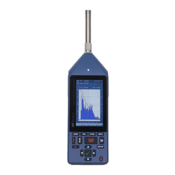
Page 17: Taking A Closer Look At The Instrument
finger tight only! The picture shows the Nor150 fitted with the standard preamplifier Nor1209 and the microphone Nor1225 mounted in sound channel one. The instrument is powered from an internal rechargeable Li-ion battery pack. -
Page 18: Switching On/Off
You may force the instrument to turn off by pressing the ON/OFF key for more than 5 seconds. Keyboard The Nor150 is mainly operated via the touch screen. There is however a dedicated backlit rubber keyboard used for operation of the main im- portant functions such as power ON/OFF, measure- ment START/STOP, PAUSE and CALIBRATION. -
Page 19: Touch Sensitive Screen
Stops an ongoing meas- use both in dark environment as well as in sunlight. The urement. Nor150 uses the latest technology for touch sensitive Pause/continue button ( ): Temporarily displays. The capacitive touch technology eliminates prevents measured data to go into the the use of a stylus or calibrating the XY position of the global results. - Page 20 Chapter 2 Taking a closer look at Nor150 Please note that the use of the backlight makes a significant impact on the power consumption. Start/Stop Pause/ Use the measurement control ( Continue ) in the touch sensitive display when you measure low noise levels.
-
Page 21: The Main Status Led
Norsonic Nor150 Instruction Manual The Main Status LED The multi-colour LED above the display indicates several operating states. Red colour indicates some type of error condition (like overload) while green colour is for positive information. State Color Behavior Description Startup/Booting... -
Page 22: Input And Output Connectors
Chapter 2 Taking a closer look at Nor150 Several sockets are located behind the rubber cover on Input and output connectors the bottom side of the instrument. Input channel 1 is located at the top of the instrument. This is the “default” channel and is the channel used LAN socket for most sound measurements. -
Page 23: On The Use Of The Internal Battery Vs. External Dc
Instruction Manual On the use of the internal battery vs. external DC The Nor150 comes with an internal Li-ion battery pack (Nor150/Battery) using the latest available charging technology. The battery pack is a so called smart battery where a build in microprocessor holds all information about the power use and charging. -
Page 24: If Power Fails
A software up- The Nor150 has a built in power saving feature that grade fee is charged if you want to upgrade to the next turns down the backlight and eventually switch itself main version (i.e. -
Page 25: Chapter 3 Your First Measurement
Assemble the instrument if it is not already done. make your own and save them for later use. See “Application Selection Menu - Predefined Setups” on Turn on the Nor150 page 65“. and wait for the start-up sequence to terminate. If needed connect the mains adapter Nor345A. -
Page 26: Saving The Measurement To The Memory
field it is recommended idea to put the shown in a table in the specifications section later in Nor150 on a tripod. It is a standard camera thread this manual. screw in mount hole at the rear side of the instrument. -
Page 27: The Measurement Functions Available
Norsonic Nor150 Instruction Manual The measurement functions available What is a Function? In the Nor150 the term is used to denote the combination of RMS (or Peak) detection with certain time constants (when applicable) and certain spectral weighting functions involving measurement duration whenever relevant. - Page 28 Function cube. So far we have yet to mention statistics. In the Nor150 statistics are either based on SPL using a user defined time constant or Leq. The statistics can be presented in several ways –...
- Page 29 Norsonic Nor150 Instruction Manual Global measurement values are a single set Three time profiles are available, Profile A, Profile B and measurement values describing entire Profile Moving. Profile A is the main profile from where measurement. Such as L etc. of the the other two are extracted.
- Page 30 Chapter 4 The measurement functions available The time profile resolution span is from 5 ms (10 ms in There is no limit to the of number weighting network dual channel mode) to 24 hours. To avoid overloading functions (A, C and Z), only the multispectrum functions. the Digital Signal Processor –...
- Page 31 Norsonic Nor150 Instruction Manual It is not possible to continue a measurement if the meas- urement is elapsed or the stop is activated manually. The term Multispectrum is octave or third octave values acquired in the time profile. One spectrum is measured per profile period.
-
Page 32: Chapter 5 Setting Up The Analyser
If a specific set up is selected in the applications The organisation of the display selection screen, the associated functions and views After the Nor150 is turned on, the applications will also be loaded. selection screen appears (Figure 5.1). If you just pass this screen or tap on the “last used”... -
Page 33: The Status Bar
Norsonic Nor150 Instruction Manual Status bar The status bar The status bar at the top of the display provides useful information about the instrument and the on- going measurement. The status bar Measurement picture 1 Battery gauge 2 Overload indication 3 Measurement status –... -
Page 34: Symbol # 2; Overload Indication
Chapter 5 Setting up the analyser Symbol # 2; Overload indication Symbol # 4, Application mode No overload Environmental Instantaneous overload. The symbol will turn to yellow after the overload disappear if a Building acoustics measurement is running. The LED on the front will also turn to red during an overload. -
Page 35: The Measurement Picture
Norsonic Nor150 Instruction Manual an ongoing measurement and Pause The softkey bar may have more function in other remove the paused values from the overall modes (Building Acoustic and Sound intensity measurement. Time profile is continuing, application). These softkeys are described in the but a pause marker is inserted in the time chapters describing these applications. -
Page 36: On-Screen Menus
Chapter 5 Setting up the analyser Special graphical displays are available in other appli- On-screen menus cations. Context sensitive menus (Figure 5.3) are available when needed. They give access to several of the Each graphical view has an associated numerical table parameters that decide the look and feel of the view available. -
Page 37: Activate And Deactivate The Result Displays
Norsonic Nor150 Instruction Manual On-screen menus: Activate and deactivate the result dis- plays Selecting SPL Live will update the SPL Live If the display is split in two halves you can tap on any of SPL values in the L(f) view also after the display parts to set it active (Figure 5.4). -
Page 38: Cursor Handling
Chapter 5 Setting up the analyser Cursor handling The main menu system - an As discussed in the previous chapter, the cursor will overview move in all display views if they are “linked”. This is The main menu appears when pushing the SETUP key useful if you want to move in the time domain and on the front panel (Figure 5.5). -
Page 39: On/Off/Available/Disabled Indication
Norsonic Nor150 Instruction Manual On/Off/Available/Disabled indication Your transducers, microphones and Input In most menus there are indications whether some- preamplifiers are specified and thing is selected or not (Figure 5.6). The green tick connected to the analyser in the means that the function is selected and the red X Input menu. -
Page 40: Selecting The Different Views And The Parameters To Display
Selecting the different views and the parameters to display Nor150 offer four different views that you can custom- L(t) - Level vs time display is a Profile display ize. You may rotate between the active views using the showing the selected level function versus time, VIEW button. - Page 41 Norsonic Nor150 Instruction Manual L(t) (Wide) (Figure 6.3) – same as Figure 6.2, but only available as landscape (wide) in single frame mode. I.e. The graphical display is turned 90 degrees. Above the L/t graph is an additional graph that shows the entire L/t trace.
-
Page 42: Function Selection - Selecting The Measurement Parameters
Chapter 6 Selecting the different views and the parameters to display NOTE! Building Acoustic and Sound Intensity mode offers other views than described here. Use the VIEW button to switch between each of the four different views. For easy use you may turn off views so that you at the extreme only have one view to deal with. - Page 43 Norsonic Nor150 Instruction Manual - Figure 6.9 Function setup Be careful when selecting the measurement parameters. Do not select more functions than what you really need. Too many functions may slow down Selects how many parameters Max Functions the performance of the measurement system and...
- Page 44 Chapter 6 Selecting the different views and the parameters to display - Figure 6.10 Select Function setup Select which sound channel data shall be retrieved from. Only applicable if the instrument is Channel fitted with the dual channel option and channel 2 is switched on. Else, this function is greyed out.
-
Page 45: Spl Live In Ended Mode
Norsonic Nor150 Instruction Manual SPL Live in ended mode It is possible to select live SPL update of the L(f) – Level vs frequency display after a measurement is finished. This feature is only offered for the L(f) view. Use the context sensitive menu to turn SPL live on/off. -
Page 46: Input Selection Menu
Input transducer to use for your measurement. You may also add new transducers or modify existing transducers or access the calibration menu. The Nor150 may be fitted with two sound channels (optional). In the example in Figure 7.1, only Sound Channel 1 active. -
Page 47: The Sound Channel 1 Or 2 Menu
Norsonic Nor150 Instruction Manual The Sound channel 1 or 2 menu Line No corrections available. The Sensor button accesses a list of available sensors (Figure 7.3). Adding, removing or modifying a sensor Microphones cannot be done from the list offered here. This is dis- When turned on, a frequency correc- Random incident. -
Page 48: The Transducer Menu
Chapter 7 Input Selection Menu If you tap on one of the fields in this case Outdoor microphones 1209&1225 a submenu with all the relevant parameters for this If any of the outdoor microphones Nor1214, Nor1216, transducer will be available (Figure 7.5). Several are Nor1217 or Nor1218 is selected, the corrections above locked and cannot be edited. - Page 49 Norsonic Nor150 Instruction Manual The name of the sensor. Give each of your microphone / preamplifier com- Name binations a name so they are easy to recognize. Name is not a locked field and may be edited. Opens up a L(t) graph which holds historical data of the calibration. Move Calibration history cursor to obtain information about previous calibrations.
-
Page 50: Adding A New Sensor
Preamplifier - Gain the signal from the microphone due to its input capacitance. Hence you should enter a negative number. Negative gain=attenuation. For Norsonic preamplifiers this value is in the range of -0.2 to -0.5 dB. Set this to 0 dB if you don’t know the gain. -
Page 51: Preamplifier Selection
ICP®, DeltaTron®, ISOTRON®, PIEZOTRON®, CCLD® and CCP®. Using other transducers The Nor150 supports a variety of transducers. A typi- cal use is the low noise microphone GRAS 40HL which may be directly connected to the Nor150. You need to specify this as a Non predefined sensor. This is an external polarized microphone, so the 200 V polariza- tion voltage must be turned on. -
Page 52: Calibrating The Instrument - Field Check
Do as follows: The Nor150 is calibrated by clicking the CAL button or in the SETUP > > > menu. - Page 53 (Figure 8.1). Calibration a calibration. The level is displayed in the L(t) Nor150 offers two different ways to perform an trace in the calibration menu. New values are set acoustical calibration, or Auto. The third Manual with the √.
-
Page 54: Microphone Check
The Nor150 has a build-in Mic. Check feature that allows this (also called SysCheck). - Page 55 Hence, a ¼” microphone will return a much lower signal level than 90 dB. The Mic. Check feature works also with the Norsonic Dehumidifier Nor1284 and Nor1285 mounted. It is recommended to not adjust the sensitivity level.
-
Page 56: Measurement Setup Menu
Chapter 9 Measurement Setup Menu Measurement Setup Menu There are a large number of parameters that can be selected for a measurement. Use the SETUP key and then the selection to confi gure the Measurement various measurement parameters (Figure 9.1). is the overall measurement time for the Global Time whole measurement sequence. - Page 57 The instrument can collect samples Percentiles (%). from one of the time weightings F or S for statistical The Nor150 fitted with option 1 offers a support Camera. calculations of the sound level. The statistical distribu- for various camera types. In this menu you configure the tion function may be calculated for both Global and use of external camera(s).
- Page 58 Chapter 9 Measurement Setup Menu • Repeat, which causes the instrument to store the acquired data and then restart immediately and make another measurement using the same measurement setup and duration. Repeat applies to measurements terminated by themselves only. If you terminate a measurement by pressing stop, the instrument will not restart.
-
Page 59: Trigger Selection Menu
It is however, often required to start a measurement based on other criteria’s than just push Figure 10.1 Figure 10.2 the start button. The Nor150 has a variety of choices found in the menu (Figure 10.2). Global Measurement Independent on the selections made in the Global Trigger menu, the START button must be pressed to activate the setting. - Page 60 The measurement start is controlled by the real time clock. Clock Trigger The measurement will start once the real time clock in the Nor150 passes the next full hour. On Next Full Hour The measurement will start once the external trigger is activated. I.e. a digital signal on the External Trigger I/O socket pin 1.
- Page 61 Norsonic Nor150 Instruction Manual The measurement will start once the level is below the set trigger level. In addition to the Level Below level, the measurement parameter can also be specifi ed. The measurement will start once the level is above the set trigger level. In addition to the Level Above level, the measurement parameter can also be specifi...
-
Page 62: The Event Trigger
Chapter 10 Trigger Selection Menu The Event Trigger An event is a significant change in the sound level for more than a minimum period of time. The amount of level change required is predefined by you by set- ting a threshold level. Hence, the purpose of the event triggers is to start an action based on the event. - Page 63 Norsonic Nor150 Instruction Manual Each of the five event triggers can be configured inde- pendently. The main purpose of offering five instead of one trigger is to associate different trigger levels dur- ing a certain time period. Each of the five triggers is connected to the real time clock.
- Page 64 This is the minimum duration the event trigger condi- See separate chapter for how to configure an external tion is not fulfilled. camera to work with the Nor150. Time Between events This is the minimum time between events. An event will be rejected if it occurs before the minimum time is reached.
-
Page 65: Chapter 11 Working With Markers
Norsonic Nor150 Instruction Manual Working with Markers Setting up Markers - the Marker Setup menu Have you ever made a measurement where you later found out that you desperately need to identify the cause of the level? Recording the audio may be one answer, but for attended measurement it may be more convenient to add markers to the measurement. -
Page 66: System Specified Markers
Chapter 11 Working with markers A red single marker labelled “C” for continues Each marker may also start an action. The following Continue; is inserted in the time profile if you terminate an ongoing actions can be assigned to a marker. measurement prematurely by pressing the STOP key The marker will start an audio recording. -
Page 67: Adding A Marker To An Ongoing Measurement
Norsonic Nor150 Instruction Manual Adding a marker to Working with markers - an ongoing measurement post processing An on-screen selection with the available markers ap- Once a measurement is elapsed, or recalled from pears in the measurement picture when the... -
Page 68: Chapter 12 Recording The Sound - Audio Record And Replay
Select 16 bit resolution if you want to replay the audio is set to 12 kHz, only frequencies up to 5 kHz can be recording on the Nor150 itself. NorReview as well as reproduced. most media players accept all formats. -
Page 69: Making A Recording
Norsonic Nor150 Norsonic Nor150 Instruction Manual Instruction Manual The instrument has a large dynamic range – Gain. Recording. exceeding 120 dB. This means that if you try to play Manually by connecting the audio recording action to back the recorded sound after having transferred the a Marker. -
Page 70: Listening - Replaying An Audio Recording
Chapter 12 Recording the sound All recordings are made in a standardized WAV-format If you want to make an automatic recording lasting which allows most media-players to play the recorded for the whole measurement, set a very low thresh- file if they are transferred to a PC. We recommend using old (e.g.: 0,0 dB) and select the Max action time to NorReview to work with the time profile data and listen- 0 min and 0 sec. -
Page 71: Chapter 13 Camera
Norsonic Nor150 Instruction Manual Camera The Nor150 fi tted with option 1 offers support for vari- ous camera types. External camera(s) is confi gured in the SETUP > > menu. The Measurement Camera internal camera is not affected by the setting in this menu. -
Page 72: Ip Camera
Note IP cameras are fully supported directly from the menu on the Nor150 after the measurement is fi n- Nor150 including event trigger control. This is the rec- ish. The pictures follow the measurement data and ommended solution for permanent or semi-permanent can be viewed in other Norsonic programs such as noise monitoring if you don’t need the remote control... -
Page 73: Chapter 14 Voice And Text Notes
Headset the existing text for the text note, while the voice note Norsonic headset Nor4584 is suitable for this use. Most only offer the possibility to replace the one you made other type of headset with microphone and a 3,5 mm prior to the measurement. - Page 74 However, this feature does not connect the notes to the applicable event marker. If this is needed, push HINT! Nor150 fitted with the enhanced environmen- the marker button and then jump to the right marker using tal option (option 11) offers a neat solution for setting the left/right arrow key.
-
Page 75: Pausing And Resuming A Measurement
Norsonic Nor150 Instruction Manual Pausing and resuming a measurement Extensive pause and continue functions are available. When paused, the instrument will produce and display the time profile for the last 20 seconds of the measure- ment. The time cursor can then be moved backwards in one seconds step to remove the unwanted noise and resumed. -
Page 76: The Difference Between A "Pause" And A "Hold" Function
(max and peak) while the measure- Figure 15.3 ment still runs. In the Nor150 this type of function is not needed since every level-display can have several parameters displayed simultaneously. It is up to the operator which results to display at any time. -
Page 77: Storing A Measurement - Memory Organising Menu
Norsonic Nor150 Norsonic Nor150 Instruction Manual Instruction Manual Storing a measurement - Memory Organising Menu The memory menu is found under SETUP > Memory. It is important to know the different storage modes Here you configure the file name conventions, storage destination, move, rename and delete files or... -
Page 78: File Name
Chapter 16 Storing a measurement The index is added to the File Name Base. Start Index. HINT! It is recommended to change the SD card If you start on one, the first file will be named “Sunny frequently to avoid data loss. Back up or transfer beach 1”... -
Page 79: Application Selection Menu - Predefined Setups
Norsonic Nor150 Instruction Manual Application Selection Menu - Predefined Setups is normally the first menu that ap- There are three different types of Setups; Instrument Application menu pears after the instrument is powered on and the boot mode, Standard setup and User defined setups. -
Page 80: Storing A Setup
Chapter 17 Application Selection Menu - Predefined Setups Selecting a setup, except from “last used” will open up Storing a Setup a “measurement info” picture (Figure 17.2) which holds A user defined setup is stored via SETUP > Memory the most important information about this setup. At the >... -
Page 81: Chapter 18 Building Acoustic
Instruction Manual Building Acoustic Introduction When equipped with the required program option(s), Nor150 is well suited for measurement of building acoustics in the form of measuring reverberation time and sound insulation. The Building Acoustics mode allows measurement of building acoustics parameters according to the ISO 16283 series of International Standards as well as National Standards like DIN, BS, SS, SIA, etc. -
Page 82: Spl Mode
Chapter 18 Building Acoustic Single-Channel views SPL Mode Figure 18.3 shows a split display with a L(f) on top of a The SPL mode appears after starting the instrument or L(t) graph. Figure 18.4 is a full screen L(f) graph. changing into BA mode. -
Page 83: Dual-Channel Views
Norsonic Nor150 Instruction Manual For single-channel instrument different colours are used to indicate the different measurement types. The colour assignment is fi xed and cannot be changed by the user (Figure 18.6). Level- Source room: Level- Receiving room: Blue Background noise: Black... -
Page 84: On-Screen Menus
Chapter 18 Building Acoustic For dual channel instruments, different colours are used to indicate the different channels (Figure 18.11). The colour assignment is fi xed and cannot be changed Figure 18.11 by the user. Channel 1: Channel 2: Blue There is a header line showing the selected standard, the measurement type (Level, BGN, RT) and the source position (#A...#D). -
Page 85: Input - Setup
Norsonic Nor150 Instruction Manual Input - Setup menu (Figure 18.14) Input selection identical with the one explained in the chap- “Selecting different views parameters to display” on page 26. Only the possibility to assign a channel to a room type is an additional feature. -
Page 86: Level - Setup (Figure 18.17)
Most Standards require 15 s but one currently supported building acoustics for measurements down to 50 Hz and 6s for meas- testing Standards in the Nor150 system, only the urements down to 100 Hz. 1/3-octaves are selectable. If ISO 10052 is the selected standard, the bandwidth is automatically •... -
Page 87: Rating - Setup
Norsonic Nor150 Instruction Manual Rating – Setup This menu (Figure 18.21) contains several sub- Rating sections for setting the different properties of the up- coming sound insulation calculation, or, for pre-enter- Figure 18.20 ing text descriptions for a fi nal test report document. -
Page 88: Source (Figure 18.21)
Chapter 18 Building Acoustic NOTE: Changing standard while there is already acquired measurement data will initiate a new pro- ject. You will be asked to save your current work and may be prompted to reuse the data. See “Start a new project” on page 89 for more information. Source (Figure 18.23) •... -
Page 89: Test Specimen
Norsonic Nor150 Instruction Manual Test Specimen Various parameters (Figure 18.27) • (Figure 18.25) is the size of the common parti- • is used for activating corrections Area BGN Corrections tion in square meters. This value is calculated based to the measured values in the fi nal calculations. By... -
Page 90: Memory - Setup (Figure 18.26)
fi le name at fi rst use. START/STOP key or the soft key to run the meas- Start urement. The Nor150 will now automatically activate • is used to store your Save Measurement Setup as the noise generator. - Page 91 Norsonic Nor150 Instruction Manual Single-Channel views while measuring: Figure 18.30 Figure 18.31 Dual-Channel Views 1 - 4 while measuring: Figure 18.32 Figure 18.33 Figure 18.34 Figure 18.35...
-
Page 92: Making The Background Noise Measurements
Chapter 18 Building Acoustic When the preset measurement duration is ended, It is a good idea to save your work frequently. We or the key is pushed the display changes its Stop advise you to store your measurement project each appearance. -
Page 93: Making The Reverberation Time Measurements
START/STOP key or the soft key to run the meas- Start urement. If the excitation type is Noise, the Nor150 will now automatically activate the noise generator. In case of Impulse excitation, it’s time for you to fi re up the im- pulse signal. -
Page 94: Data Mode
Chapter 18 Building Acoustic Display in Data Mode It is a good idea to save your work frequently. We The Data mode has a fixed set of 4 display views. advise you to store your measurement project each Compared to the Environmental Mode these views time you have accepted a measurement. -
Page 95: Rating Views 1 - 4
Norsonic Nor150 Instruction Manual Rating views 1 - 4 Figure 18.43 Figure 18.44 Figure 18.45 Figure 18.46 Rating View-1 Figure 18.43 presents the calculated sound insulation together with the single number index according to the selected standard in a dual frame. The upper frame shows the results graphically while the lower frame contains the numerical values. -
Page 96: Rating View-2
Chapter 18 Building Acoustic Rating View-2 Rating View-4 Figure 18.44 is a plain numerical table to present the This view (Figure 18.46) contains information about single number index along with the spectrum adaption the infl uence of the background noise to the receiv- terms. -
Page 97: Measurements Views 1 - 4
Norsonic Nor150 Instruction Manual • L2 or L2’: average sound pressure level in the re- The views for the reverberation time and the views for ceiving room (L2’ means it’s corrected for back- the sound pressure levels are in principle the same. It’s ground noise) only the unit and the scaling that is different. -
Page 98: View 1- 4 For Reverberation Time Measurements
Chapter 18 Building Acoustic View 1- 4 for reverberation time measurements: Figure 18.51 Figure 18.52 Figure 18.53 Figure 18.54 View 1 - 4 for receiving room measurements: Figure 18.55 Figure 18.56 Figure 18.57 Figure 18.58... -
Page 99: Measurement View-1
Norsonic Nor150 Instruction Manual Measurement View-1 • SD: Standard Deviation of the average View-1 presents the average of accepted measure- • N: Number of measurements included in the aver- ments in a graphical and numerical way. It covers all microphone and source positions. If available, use the Screen shot of Receiving average limited to source po- soft key to display the average of a specifi... -
Page 100: Measurement View-2
Chapter 18 Building Acoustic Measurement View-2 View-2 displays the average and its included measure- ments graphically and in a table. This is helpful to see how the different microphone positions vary. If available, use soft key to display the average of a specific source position #A…#D and the measurements belonging to it. -
Page 101: Measurement View-3
Norsonic Nor150 Instruction Manual Screen shot (Figure 18.61) of Receiving room total (All) Measurement View-3 average and its measurements View-3 displays the average and just one of its meas- urements graphically and in a table. This is to com- • Avg: Energetic (Level) or linear (Reverberation) av- pare one microphone position with the average value. -
Page 102: Measurement View-4
Chapter 18 Building Acoustic Measurement View-4 View-4 presents the selected microphone position (not the average!) from the previous view as a Level vs frequency L(f) and Level vs time (L(t) graph. Use the arrow keys on the keyboard to select a different microphone position. -
Page 103: Start A New Project
Norsonic Nor150 Instruction Manual Start a new project To start a new project pushing the button to close the current measurement project and start a new one. You may be asked to save the current data (Figure 18.68). If you want to reuse some or all of the current data click when prompted (Figure 18.69) and select the... -
Page 104: Chapter 19 Sound Intensity
, sound power, and FpI. The range of available func- tions depends on the selected measurement standard. The Nor150 will, in combination with the Nor1290 probe and the Nor1294 phase verifi cation coupler, ensure that most intensity measurements may be performed with a single 12 mm spacer. -
Page 105: Setting Up The Instrument For Intensity
Instruction Manual Setting up the instrument for intensity The Nor150 may utilize a wide range of probes, both pre-polarized and 200 V polarized microphones in different configurations. However, the highest perfor- mance and ease of use is achieved using the Nor1290 probe kit. - Page 106 To use the probe handle, connect the probe at the top of the rod, then add an extension cable between the bottom end of the rod and the Nor150. The optional smartphone will provide the same view as the Nor150 itself, offering a one-hand operation of intensity meas- urements.
-
Page 107: Probe Dismantling
Probe dismantling Transducer setup To do probe calibration and verification, it is necessary For customers buying the Nor150 with the Nor1290 to dismantle the probe. Open the spacer adjustment probe kit, all settings are predefined from the factory. knob (see Figure 19.3) and pull the microphones apart Setting up the probe is then easily done: as shown in Figure 19.6. - Page 108 Chapter 19 Sound Intensity If the kit is delivered separately, the parameters of the Microphone capsule transducers and the probe must be set up before the “Pressure in air ref 20e-6 Pa” Measurand: probe may be used. We recommend to use the lower as specified in the cal.
-
Page 109: Connecting A Smartphone
WiFi is necessary to download the application. menu system. Press the refresh button in the NorRemote app (Figure 19.15). The name of the Nor150 will show up. Tap the name to connect (Figure 19.16). - Page 110 Figure 19.13 - Figure 19.14 - The WLAN Figure 19.15 - Press the Figure 19.16 - Tap on the The WiFi dongle. connection menu. refresh button to update Nor150 name to connect. the device list.
-
Page 111: Calibration And Phase Correction
“Probe dismantling” on page ??. Pressure calibration Insert probe microphone A into a sound calibrator such as a Nor1251. Open the calibration menu on the Nor150 by pressing CAL. The calibration menu is shown in Figure 19.17. Select Pressure calibration then 1. -
Page 112: Phase Correction
Nor1294 into CLOSED position as shown in Figure 19.21. Connect the Nor1294 mini-jack into the headset output of the Nor150. Then press the START soft key to initiate the correction process. A progress bar will keep you updated, and the calibra- tion is fully automatic. - Page 113 Norsonic Nor150 Instruction Manual Figure 19.22 - Phase cor- Figure 19.23 - Correction rection in progress. Allow finished. Accept or dis- about 30 seconds for the card the correction. correction process. HINT: The instrument will warn you if it detects too low sound pressure during the calibration process.
-
Page 114: Verification Procedure
“Calibra- tion and phase correction” on page ??. The residual spectrum data is stored in the Nor150 along with time and date. Thus, it is possible to look at the previous calibration or verification, and track the history. -
Page 115: Configuring An Intensity Measurement
SETUP menu (Figure 19.26). Figure 19.26 - Press the Figure 19.27 - The sound The Nor150 intensity mode offers different setups when “New” button to start a intensity setups. pressing the SETUP key, followed by a tap on Applica- new project. -
Page 116: Probe And Environment Parameters
Before a measurement is started, the probe must be In intensity mode, the Nor150 organises measure- configured. For the Nor150 in combination with the ments in projects. Normally, the user will define a Nor1290 kit, the 12 mm spacer is the correct choice measurement surface enclosing the sound source to for most measurement applications. - Page 117 Norsonic Nor150 Instruction Manual Back Right Segment in surface Left Surface the Front surface Left Front Figure 19.32 - The cuboid is divided into surfaces, and each Figure 19.33 - Intensity measurement with fi xed probe surface is built up of one or more segments.
- Page 118 Figure 19.36. When entering the surface dimensions, the Nor150 will divide the surfaces (e.g. left) into several segments, such that no segments will have an area of more than 1 .
-
Page 119: Measurement Settings
filter settings, as long as measurement has been performed, causing a recalcu- the respective bands has been measured. Norsonic lation of sound power if this part of the measurement. recommends to always set the Filter range to span Figure 19.38 shows the options available for a cuboid... - Page 120 Selecting a standard The sound intensity mode in the Nor150 will provide different measurement functions based on the select- ed measurement standard. Warnings, functions and views will be configured accordingly.
-
Page 121: Navigating The Sound Intensity Mode
In Sound Intensity Mode, some of the measured quan- indicated with a negative sign in a parenthesis in front tities are levels with a direction. The Nor150 indicates of the value. Note that sound pressure has no direc- this property by a Mirror graph. The mirror graph... -
Page 122: Introducing The Surface Scopes
Back As discussed in “Defining a measurement surface” on navigate upwards in the scope hierarchy. Figure 19.42 page 102 the Nor150 operates with the concept of shows the navigation steps. a total measurement surface divided into several sur- faces and segments. To enable easy navigation in the... - Page 123 Norsonic Nor150 Instruction Manual Scope view The scope view provides a graphical representation of the measurement surface for the Total scope and the Surface scope, as discussed in the previous section. When viewing the total scope, scope view presents the A-weighted values for the whole measurement surface along with the currently selected surface.
- Page 124 Chapter 19 Sound Intensity Running view This is the view which appears when a measurement is running. Leq, Ieq and IfSPL (time constant fast) is displayed. Figure 19.49 shows how the running view typically looks. Simple view If inside a scope view, pressing the VIEW button will bring you the simple view representation for the current scope.
-
Page 125: Errors And Warnings
Norsonic Nor150 Instruction Manual Errors and warnings Warning for weighted sum The Nor150 calculates field indicators and evalu- frequency range (A/C/Z) ates criterions belonging to different standards in the background after each measurement. Deviations from a perfect measurement is indicated by warning Cursor position warning triangles. -
Page 126: Saving And Loading Intensity Projects
Chapter 19 Sound Intensity Saving and loading intensity projects The Nor150 in intensity mode automatically saves a project using the current date and time when a meas- urement is started. However, to assign a name to the project, press the MEM button. - Page 127 Instruction Manual The measurement pictures are always synced while using the smartphone. Pressing a key on either the Nor150 or the smartphone will cause both devices to do the change. Thus, no additional configuration is necessary. The smartphone displays the VIEW, TBL, FUNC and INFO keys in addition to the softkeys on-screen.
-
Page 128: Sound Power Using Iso 9614-2
Engineering grade accuracy requires two orthogonal NOTE: The measurement surface represents the scans for each segment. These are denoted Horizontal surface of which the probe should have its acoustical on the Nor150. If survey grade is desired, Vertical centre. -
Page 129: Measuring
Norsonic Nor150 Instruction Manual Before the measurement is started, the environmental HINT: If an obstacle is encountered during a scan, parameters must be set up and the probe calibrated press the key. The measurement will be paused. as described in “Probe and environment parameters”... -
Page 130: Reviewing The Measurements
field indicators in addition to the sound power and sound intensity. The indicators are presented in separate views in the Nor150. Below is an overview of the data presented in the different scopes. HINT: The concept of scopes is discussed in sec- tion “Introducing the surface scopes”... - Page 131 Norsonic Nor150 Instruction Manual The second graph displays dynamic capability along with the field indicator FpI, as illustrated in Figure 19.65. If two scans have been made on the segment, a third graph is available. This graph shows the difference (∆) functions generated based on the two scans as illus- trated in Figure 19.66.
- Page 132 Chapter 19 Sound Intensity Advanced view Simple view Two different graphs are presented by toggling the A spectrum is presented for sound pressure along with FUNC key. The warning window is available for all either sound intensity or sound power. Warnings are graphs by pressing the INFO button.
-
Page 133: Measurement Functions And Indicators
Norsonic Nor150 Instruction Manual Measurement functions and indicators Warning indicators Dynamic capability too low – Trigged if the FpI ex- Sound power measurement according to ISO 9614-2 ceeds the dynamic capability for a frequency band. uses the intensity values to generate sound power lev- els for each individual segment, and summing these High FpI –... -
Page 134: Chapter 20 Instrument Specific Setup
Setup – The line goes high when the This menu (figure 20.1) holds all the setup related to Remote controlled Nor150 is controlled from another device. the peripherals, power saving settings, language etc. – The line stays permanently high. High... - Page 135 Name, e-mail, product type and serial number Nor1441B to connect the unit to a PC via the RS232 of the Nor150 to access the download site. The only interface. reason for asking for your contact data is to enable us...
-
Page 136: The Software License System
Sound Intensity or Building Acoustic for the measurement of sound insulation including The Nor150 offers a 60 days trial period where all options measurement of the reverberation time. Please note that is enabled. Activate the trial period in the SETUP >... -
Page 137: Signal Generator (Optional)
Norsonic Nor150 Instruction Manual Remote Properties. Signal Generator (Optional) A signal generator is added in the Nor150. This facili- If the device (Nor150) has a another Public Host: tates the use of the instrument for various applications. IP address than default local address, this should be named here. -
Page 138: Chapter 21 Norsonic Software
(freeware included in the delivery). One may say NOTE! NorXfer does not support the Nor150. it is for the Nor150 what the NorXfer is for the other Nor13x and Nor140 instruments. Additionally it has a viewer function that displays the L(t) and L(f) data and... -
Page 139: Description
Norsonic Nor150 Instruction Manual We have chosen to use USB port on the Nor150 instru- the measurement(s), and click on one of the reports ment for download of measurements. Connect the icons (Excel or a specific post-processing program to Nor150 to the PC using the delivered USB cable. This is produce the desired report. - Page 140 Chapter 21 Norsonic software Figure 21.1...
-
Page 141: Quick Reference Guide
Norsonic Nor150 Instruction Manual Quick Reference Guide Connecting the instrument Connect the Nor150 to the PC via USB (at IP address 10.150.150.1) as explained Connected instrument “Nor150” is shown in Figure 21.2. NOTE: The name “Nor150” is read from the instru- ment. - Page 142 Chapter 21 Norsonic software Figure 21.4 Figure 21.5...
-
Page 143: Making Reports
Norsonic Nor150 Instruction Manual Making reports There are basic reports in Excel format easily at hand To simply report just the data measured, choose Over- view, click the arrow just below the Excel button on the menu line, then “Overview” (Figure 21.6). - Page 144 Chapter 21 Norsonic software The measurement results are found in tabs as Global- and profile values for each report S1 and S2 (and Mov- ing if measured) as shown in Figure 21.7. Figure 21.7...
-
Page 145: Building Acoustic- And Sound Intensity Measurements Reports
Norsonic Nor150 Instruction Manual Building Acoustic- and Sound Intensity For the intensity report, here are individual tabs for each segment, as well as for the Total Surface (Figure 21.10 measurements reports and an Overview (Figure 21.11). There are also similar Excel reports for building acous- tics and intensity measurement files. - Page 146 Chapter 21 Norsonic software Figure 21.9 - Intensity measurement report Figure 21.10 - Intensity report - Overview Figure 21.11 - Intensity report - Total surface...
-
Page 147: Details
This means that the default view always shows the last Details measured file on top when you browse the memory of the Nor150 connected! File browser A file browser shows the content of the instrument in PS! You may change the way the measurements the right hand frame. -
Page 148: Sd Card Connection
Chapter 21 Norsonic software This makes it easy to locate the last file taken in each SD card connection category. Alternatively, to connecting the meter via the USB ca- ble, you may remove the micro SD card from the meter You may choose a network location for your files instead... -
Page 149: Graph View
Norsonic Nor150 Instruction Manual You may also use Zoom in/out functions as found under Graph view “graph tools” (Figure 21.19) and listen to audio record- For “General Analyser” measurements you may use ings using the standard Windows Media Player (click the “Graph view”... -
Page 150: Choose/Add Function
Chapter 21 Norsonic software Choose/add function Other functions may be added. Just click the green + sign (Figure 21.21). Select among available functions HINT! You can “dock” this window conveniently to a specific location Right-click function to change colour and style (Figure Figure 21.21... -
Page 151: Concatenate Measurements
When you are doing Repeat- or Synchro measure- header, then select one of the “Sub-measurements ments with the Nor150, all individual files will be put into the same folder. NorConnect offers a function called “Concatenate” (Figure 21.23) to get a summary of these files. -
Page 152: Sort Criteria
Sort criteria In the example in Figure 21.25 “Date” is selected as the 3rd sort criteria, following “Name” (2nd) and “Mode” Default sorting applied when browsing the Nor150 (1st) memory is by “Mode” then “Date”. This is marked with a small number 1 and 2 in the header of the columns You may also change the default grouping for the as shown in Figure 21.24. - Page 153 Norsonic Nor150 Instruction Manual Figure 21.26...
-
Page 154: Excel Reports
Chapter 21 Norsonic software Excel reports There are several possible reports Gen. Mode: advanced possibilities with either self-made or customized templates, latter as in- cluded in installation Click the Excel icon and choose among the re- ports available. All modes: Overview report. These are “hardcod- ed”, ie. -
Page 155: Enhanced Reports With Nor850 And Norreview
Norsonic Nor150 Instruction Manual Enhanced reports with Nor850 and NorReview If you have installed the programs Nor850 and/or NorReview you may also use these directly from the menu line to post-process the measurements. Nor850 program can be used for building acoustics-, sound power- and intensity measurements, while NorReview is used for the category “General Analyzer”... -
Page 156: Where Are My Measurements Stored
Chapter 21 Norsonic software Where are my Measurements stored? The default directory is You may however select any directory for your meas- urements. Use the browser to select/make/change di- rectory. See Figure 21.30. NOTE that when you exit the program the current (last) directory is shown when you start up again Figure 21.30... -
Page 157: Search
Norsonic Nor150 Instruction Manual Search It is possible to search for files on the PC or a measure- ment. Just key in a search phrase, eg part of the file/ measurement name You may also narrow your search by applying different filter criteria (Mode, Date) on the connected instrument/... -
Page 158: Initialize Nor150 Usb
Select your preferred language. This is applied when Nor150, you can choose to do so later. the program is restarted (Figure 21.33) Connect the Nor150 to the PC with the USB cable Nor4525. The USB in the meter must be set to “Normal” with the Static IP address at 10.150.150.1. -
Page 159: Info
Norsonic Nor150 Instruction Manual Info The reset button (Figure 21.34) is a useful tool to ap- ply to reset to the default view properties, eg. when a special sorting criteria shall be reset. Figure 21.34... -
Page 160: Chapter 22 Technical Specifications
The instrument also conforms to a number of national Firmware version standards such as: DIN 45657 (2013-02-06). The specifications in this manual are valid for a Nor150 with software version 1.2 and above. The version number can be found using the SETUP >... -
Page 161: Analog Inputs
Nor1290 and some other probes is seleced Input connector GND - signal reference 7 pin LEMO connector for Norsonic microphone sys- Polarization voltage – selectable: 0±1V, tems. (LEMO ECG.1B.307.CLL) 200±1V or adjustable 70 to 74 V short-circuit Input impedance direct connection to input socket: current <1mA, impedance: 2 MOhm... -
Page 162: High-Pass Input Filter
62 dB re 20 µPa Highpass filter frequency response Weight: 6.5 g Preamplifier The standard preamplifier for Nor150 is Nor1209. But different types of preamplifiers can be used. The instrument has the ability to correct for the attenuation Filter “OFF”... -
Page 163: Nor1209 Data
Norsonic Nor150 Instruction Manual Nor1209 data The microphone preamplifier Nor1209 has been de- signed for general use with most ½” condenser micro- phone of type WS2 or LS2 according to IEC 61094-4: Measurement microphones - Part 4: Specifications for working standard microphones. The microphones may be pre-polarized or use externally supplied polariza- tion voltage up to 200 V. -
Page 164: Nor1209 Technical Specifications
A typical value for mi- A-weighted < 2,2µV (typically 1,8µV) crophone cables from Norsonic is 120 pF per metre. Noise (20 pF dummy microphone): Hence, a cable with length 100 m, will load the out- Lin (20 Hz –... -
Page 165: Acoustical Data
Norsonic Nor150 Instruction Manual Acoustical data Acoustical data for Nor1225 and Nor1209 mounted on Nor150 The following tables gives free field frequency response and uncertainty information for the complete Reference direction: sound level meter. The microphone reference direction is from the micro-... - Page 166 Chapter 22 Technical specifications Detailed table for level corrections according to IEC 62585 Expanded Expanded Typical Pressure to Expanded Nominal Exact free-field free-field uncertainty Case uncertainty Windscreen uncertainty windscreen frequency frequency response correction Pressure-FF correction case corr. correction 63,1 0,00 0,00 0,05 0,00...
- Page 167 Norsonic Nor150 Instruction Manual Expanded Typical Pressure to Expanded Expanded Nominal Exact free-field free-field uncertainty Case uncertainty Windscreen uncertainty frequency frequency response correction Pressure-FF correction case corr. correction windscreen 2113,5 -0,07 0,34 0,13 -0,01 0,10 0,12 0,03 2238,7 -0,08 0,36...
- Page 168 Chapter 22 Technical specifications Expanded Typical Pressure to Expanded Expanded Nominal Exact free-field free-field uncertainty Case uncertainty Windscreen uncertainty frequency frequency response correction Pressure-FF correction case corr. correction windscreen 10 k 10000,0 0,48 5,01 0,30 0,25 0,20 -0,68 0,11 10592,5 0,54 5,50 0,38...
-
Page 169: Directional Response - Horizontal
Norsonic Nor150 Instruction Manual Directional response – Horizontal Maximum absolute value of the difference between displayed sound levels at any two sound-incidence angles within ±ө degrees from reference direction. - Page 170 Chapter 22 Technical specifications Directional response...
-
Page 171: Directional Response - Vertical
Norsonic Nor150 Instruction Manual Directional response - Vertical The directional response of the complete instrument is measured in the horizontal direction (sideways, with the display facing upwards). Zero degrees are in the direction of the microphone. - Page 172 Chapter 22 Technical specifications Directional response...
-
Page 173: Directional Response - Horizontal With Wind Screen
Norsonic Nor150 Instruction Manual Directional response – Horizontal with Wind Screen The graphs and plots below show the directional re- sponse for the complete sound level meter Nor150 with preamplifier Nor1209, microphone Nor1225 and windscreen Nor1451. - Page 174 Chapter 22 Technical specifications Directional response...
-
Page 175: Directional Response - Vertical With Wind Screen
Norsonic Nor150 Instruction Manual Directional response – Vertical with Wind Screen The graphs and plots below show the directional re- sponse for the complete sound level meter Nor150 with preamplifier Nor1209, microphone Nor1225 and windscreen Nor1451. - Page 176 Chapter 22 Technical specifications Directional response...
-
Page 177: Verification Of The Free Field Response
Frequency weightings sponse There are several ways to verify the acoustical perfor- mance of the Nor150. For periodic verification accord- Weighting networks: ing to IEC 61672-3 Ed.2.0 it is recommended to use a The Nor150 simultaneously measure the three weight- multi frequency calibrator. -
Page 178: Detector Type
• S–time-weighted sound pressure level, instantaneous Each individual microphone transducer connected to • Maximum S–time-weighted sound pressure level the Nor150 can have its own low level information. In the transducer set up menu the operator can key in • Minimum S–time-weighted sound pressure level the lowest acceptable level information for each 1/3rd •... -
Page 179: Level Distribution
These indications are in use both on the graphical dis- Statistics plays and on the numerical tables. The Nor150 can be equipped with a statistical level Time weighted sound levels are indicated on screen distribution function. Up to eight percentiles can be as follows based on Time Constant (F, S or I) and shown numerically in a table. -
Page 180: Indication Range
Chapter 22 Technical specifications Self-noise levels A-Weighted C-weighted Z-weighted The self-noise is measured with the calibration set to –26.0 dB corresponding to a microphone sensitivity of 50 mV/Pa. For voltage input, the level 0 dB then cor- responds to 1µV. F Max LAFmax LCFmax... -
Page 181: Acoustic Self-Noise
Norsonic Nor150 Instruction Manual Acoustic self-noise Measurement duration and The acoustic self-noise is measured with Nor1225 mi- resolution crophone and preamplifier Nor1209 connected. Global (Overall) measurement: The total time for a measurement may be set from 1 second up to 7 days The high-pass filter (in the Setup Input menu) shall be... -
Page 182: Measurement Ranges
Chapter 22 Technical specifications In synchro and repeat mode the stop of one measure- For compliance with IEC60804 type 1, the linearity range ment and the start of the next is handled without time is 24 to 137 dB, and the pulse range 24 dB to 140 dB, gap. -
Page 183: Measurement Range For C-Weighted Peak Levels
Then the instrument 4 hours (80% in 2 hours) can also be configured to feed an IEPE device. No other battery type than Nor150 / Battery from Norsonic can be used in the instrument. Replacement Electrical verification measure-... -
Page 184: Power Consumption
Never waste the battery without knowing that it will be Mains adapter Nor345A handled as required. If you are in doubt, return it to the The Nor150 is delivered with a mains adapter. This Norsonic representative. adapter can be fitted with connector for different mains systems. -
Page 185: Adjustment Of Indicated Levels
Norsonic Nor150 Instruction Manual Adjustment of indicated levels Random response The instrument is equipped with a microphone with flat free-field response and satisfies the class 1 require- ments in IEC 61672-1 to free-field response. By select- ing the random response correction network included,... -
Page 186: Diffraction Around The Instrument Casing
Chapter 22 Technical specifications Diffraction around the The general I/O socket instrument casing The instrument casing and the microphone is de- signed to have low effects on the sound field in which it is measuring. Nevertheless there is some influence Signal and it is also dependant on the environmental condi- Pin no. -
Page 187: Signal Output - Noise Generator
Frequency response re. 1 kHz: ±0,5dB for 20 Hz < Digital output control lines f < 16 kHz. The Nor150 instrument has 4 general digital output lines which all can be used to alarm and control exter- Signal output – Microphone signal nal devices or functions based on the internal status of the instrument. -
Page 188: Headset Input And Output Socket
Instrument Communication electrostatic actuator calibration feature in the out- ber is set to 8501. The easy way is to set the Nor150 to door microphone 1210A or C automatically receive its IP address from the network. – The line goes high when the... -
Page 189: Environmental Conditions
But when the Nor150 is brought from one room to for any of the frequencies 31,5 Hz, 63 Hz, 125 Hz, 125... -
Page 190: Sensitivity For Magnetic Fields
The sensitivity for a mains power frequency field than 1.3dB. is small. The instrument performs according to the The most sensitive setup is when the Nor150 is con- requirements in the sound level meter standard when nected via an extension cable (Nor1208/50) to the the microphone / preamplifier is connected to the... -
Page 191: Recovery After Electrostatic Discharge
Instruction Manual Recovery after electrostatic dis- charge The Nor150 is constructed to have high immunity towards electrostatic discharge as required in the sound level meter standard. It will operate normally when exposed to a contact discharge of ± 4 kV or an air discharge of ±... - Page 192 Appendix 1 Index Index Symbols BA mode 68 Battery lifetime 9 1/10 dB Accuracy 75 Battery lov 7 Battery Low 7 BGN 67 BGN Corrections 75 About 121 Bind Network or Frequency 30 Airborne 67 Building Acoustic 67 Airborne Sound Insulation calculations 67 Analoge inputs 147 Analog Output 121 application menu 65...
- Page 193 Norsonic Nor150 Instruction Manual Data Mode 68 Global Time 42 decay 73 Global Trigger 45 DeltaTron®, 37 Go To 23 Denotes 03 graph tool 125 Digital I/O 120 Guest Password 123 Draw order 30 Duration 72 Hard Disk 63 Headset 8 High-pass input filter 148...
- Page 194 Appendix 1 Index Memory 25 Memory Organising Menu 63 L1 82 Mic Check 39 L2 82 Mic. Check 120 L2’ 82 Microphone capsule 35 Communication 121 Microphone check 40 LAN 121 Micro SD card socket 8 Language 121 Min distance to noise floor 72 LAN socket 8 Min Duration Out 50 Lb 82...
- Page 195 Norsonic Nor150 Instruction Manual Preamplifier - IEPE 36 Preamplifier - Serial Number 36 Save Internal Info 123 Preamplifier - Type 36 SD card 63 Primary RT function 73 Service Menu 123 Profile Time 42 Set Factory Default 123 Public Host 123...
- Page 196 Appendix 1 Index Threshold type 49 Time Between events 50 Timeout 123 Time Span 50 Time Weightings 42 touch sensitive display 4 Touch sensitive screen 5 Transducers 34 Trigged at 72 Trigger 25 Trigger function 49 USB 121 USB memory stick 63 Verification - Date 35 Verification -Date 35 Verification -Interval 35...
-
Page 197: Declaration Of Conformity
EN 61010-1 IEC 61043 class 1 This product has been manufactured in compliance with the provisions of the relevant internal Norsonic production standards. All our products are tested individually before they leave the factory. Calibrated equipment—traceable to national and international standards—has been used to carry out these tests. - Page 198 P.O. Box 24 Norsonic AS supplies a complete range of instrumentation for acoustics – from sound calibrators, microphones N-3421 Lierskogen and preamplifiers; via small handheld sound level meters to advanced, yet portable, real time analysers, but Norway Tel: +47 3285 8900...
Need help?
Do you have a question about the NOR150 and is the answer not in the manual?
Questions and answers