Table of Contents
Advertisement
Quick Links
INSTRUCTION
MANUAL
INSTRUMENT SOFWARE 3.0
Norsonic has always been at the
forefront introducing new technology
to sound level meters. The Nor145
Sound Analyser sets a new standard in
user-friendliness. Featuring the largest
colour touch screen in a handheld
meter on the market today, the Nor145
provides the user-friendliness of a
smart phone. Further features include
built in web server, LTE and WiFi,
GPS, sound recording, voice and text
notes, sophisticated marker handling
and event triggers in addition to high
resolution time profile, multi-frequency
spectra and on board BA rating
bringing the sophistications normally
found in laboratory instrumentation out
in the field. The instrument is designed
to cover a variety of applications
besides being a sophisticated sound
level meter. This instruction manual
is covering software version 3.0
which with its features address the
noise assessment, noise monitoring
and building acoustics market.
nor145
SOUND ANALYSER
Advertisement
Table of Contents

Related Manuals for Norsonic nor145


Summary of Contents for Norsonic nor145
- Page 1 Sound Analyser sets a new standard in user-friendliness. Featuring the largest colour touch screen in a handheld meter on the market today, the Nor145 provides the user-friendliness of a smart phone. Further features include built in web server, LTE and WiFi,...
- Page 2 Norsonic AS reserves the right to amend any of the information given in this manual in order to take account of new developments.
- Page 3 Thank you for choosing Norsonic! The instruction manual describes a fully equipped instrument. Your version of the instrument may not The Nor145 has been designed to give you many years have all the optional extensions available. Software of safe, reliable operation.
-
Page 5: Table Of Contents
Norsonic Nor145 Instruction Manual Contents Chapter 1 Important information �����������������������������������������������������������������������������������������������������1 Safety instructions ..........................1 Precautions ............................2 Chapter 2 Taking a closer look at the instrument��������������������������������������������������������������������������4 Switching ON/OFF ..........................5 Keyboard ............................5 Touch sensitive screen ........................7 The Main Status LED .......................... 8 Input and output connectors ...................... - Page 6 Contents Chapter 4 The measurement functions available ������������������������������������������������������������������������ 14 Chapter 5 Setting up the analyser ������������������������������������������������������������������������������������������������� 19 The organisation of the display ......................19 The status bar ..........................20 Symbol # 1 Battery gauge / external power ................20 Symbol # 2; Overload indication ....................21 Symbol # 7, Measurement status ....................21 Symbol # 8, Application mode ....................21 The soft key bar ...........................21...
- Page 7 Norsonic Nor145 Instruction Manual Chapter 9 Measurement Setup Menu ��������������������������������������������������������������������������������������������44 High-pass input filter ........................45 Weather Station ...........................47 Chapter 10 FFT ����������������������������������������������������������������������������������������������������������������������������������48 Introduction ............................48 How to select FFT ..........................48 Making a measurement ........................48 Calibration ............................49 Corrections ............................49 Chapter 11 Trigger Selection Menu �������������������������������������������������������������������������������������������������50...
- Page 8 Contents Chapter 17 Storing a measurement - Memory Organising Menu ��������������������������������������������������68 File name ............................69 Unique Measurement identifier ......................70 Save and Manage Measurement setup ................... 70 Write Protected Setup ........................70 Rename, Delete, Move ........................70 Set Factory default..........................71 Save Debug Log ..........................71 Chapter 18 Application Selection Menu - Predefined Setups ������������������������������������������������������72...
- Page 9 Norsonic Nor145 Instruction Manual Project Mode ..........................87 Display views in Project Mode .....................87 Rating views 1 - 4 ........................89 Rating View-1 ........................89 Rating View-2 ........................90 Rating View-3 ........................90 Rating View-4 ........................90 Measurements views 1 – 4 ....................91 View 1 - 4 for reverberation time measurements: ..............92 View 1 - 4 for receiving room measurements: ..............92...
- Page 10 Input connector .........................127 Microphone input socket (outside view) ...................127 High-pass input filter ........................128 Nor1227 technical data ......................128 Preamplifier............................. 129 Nor1209 data ........................... 129 Nor1209 Technical data in combination with Nor145; ............. 129 Windscreen ..........................129 Cables and cable length ........................ 130...
- Page 11 Norsonic Nor145 Instruction Manual Acoustical data for Nor1227 and Nor1209 mounted on Nor145 ............130 Reference direction: ..........................130 Microphone Reference Point ......................... 130 Corrections used for verification and stating conformance to EN/IEC 61672-1 ........131 Detailed table for level corrections according to IEC 62585 ..............132 Directional response –...
- Page 12 Total range for measurement of C-weighted levels ..............152 Total range for measurement of Z-weighted levels ..............152 Measurement range for C-weighted peak levels ..............152 The Nor145 used for electrical measurements ................153 Electrical verification measurements ..................... 153 Power supply ..........................153 Internal battery ........................
- Page 13 Norsonic Nor145 Instruction Manual Environmental conditions ........................159 Warm-up time ..........................159 Changes in the environmental conditions ..................159 Sensitivity to static pressure ......................159 Sensitivity for vibration ........................159 Sensitivity for magnetic fields ......................160 Sensitivity for radio frequencies ..................... 160 Emission of radio frequencies ......................160 Sensitivity for AC power frequency ....................
- Page 15 SOUND ANALYSER...
-
Page 17: Important Information
• Only use attachments/accessories allowed or specified by Norsonic AS. • Be careful when using the instrument on a tripod or NOTE Damaged batteries are strictly prohibited to in combination with a rotating boom. -
Page 18: Precautions
… even the instrument is a field instrument, prevent it from direct contact with dust and moisture. … Nor145 is a measurement instrument; protect it from impacts and strong vibration. … never store the instrument with empty batteries. This may permanent damage the batteries. - Page 19 Norsonic Nor145 Instruction Manual This equipment has been tested and found to comply with the limits for a Class B digital device, pursuant to part 15 of the FCC Rules. These limits are designed to provide reasonable protection against harmful interference in a residential instal- lation.
-
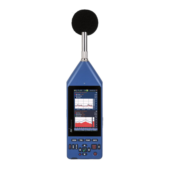
Page 20: Taking A Closer Look At The Instrument
Be sure to take utmost care when mounting a micro- phone cartridge onto a preamplifier. Finger tight only! The picture shows the Nor145 fitted with the standard preamplifier Nor1209 and the microphone Nor1227. The instrument is powered from an internal recharge- able Li-ion battery pack. -
Page 21: Switching On/Off
You may force the instrument to turn off by pressing the ON/OFF key for more than 5 seconds. Keyboard The Nor145 is mainly operated via the touch screen. There is however a dedicated backlit rubber key- board used for operation of the main important functions such as power ON/OFF, measurement START/STOP, PAUSE and CALIBRATION. - Page 22 Chapter 2 Taking a closer look at Nor150 In this manual the following symbols are used to Cursor buttons ( ): Keys for mov- indicate the keyboard buttons: ing the cursor in graphical and tabular displays. The cursor buttons may have View button (VIEW): Switch between the different functionality in the different dis- four available view setups.
-
Page 23: Touch Sensitive Screen
The large 4.3” capacitive touch display is optimised for use both in dark environment as well as in sunlight. The Nor145 uses the latest technology for touch sensitive displays. The capacitive touch technology eliminates the use of a stylus or calibrating the XY position of the screen. -
Page 24: The Main Status Led
Chapter 2 Taking a closer look at Nor150 The Main Status LED The multi-colour LED above the display indicates several operating states. Red colour indicates some type of error condition (like overload) while green colour is for positive information. State Color Behavior Description... -
Page 25: Input And Output Connectors
DC Several sockets are located behind the rubber cover at the bottom side of the instrument. The Nor145 comes with an internal Li-ion battery pack (Nor145/Battery) using the latest available charging LAN socket. technology. The battery pack is a so called smart battery where a build in microprocessor holds all USB OTG socket. -
Page 26: Charging The Internal Battery
NOTE! Always fully recharge the battery before you store the instrument. Fully recharge every third The Nor145 has a built in power saving feature that month if the instrument is not in use. The battery turns down the backlight and eventually switch itself may be permanent damaged if this procedure is not off if left unattended in ready mode (I.e the instrument... -
Page 27: Optional Extensions
Such features can be Optional extensions adaption to new revisions of measurement standards, The Nor145 comes with an extensive set of functions new measurement functions or new and easier use of available in its basic version. Many other functions the instrument. -
Page 28: Your First Measurement
Chapter 3 Your first measurement Your first measurement Make sure you have read the section “Taking a closer Select a standard set up look at the instrument” on page 4 earlier in this The easy and repeatable way to perform a measure- instruction manual. -
Page 29: Saving The Measurement To The Memory
(available with the SETUP button). Input Menu Nor145 on a tripod. It is a standard camera thread screw mount hole at the rear side of the instrument. When the wind screen is fitted and the correction is turned on the measurements performed will still be within the specifications of a type 1 sound level meter. -
Page 30: The Measurement Functions Available
Chapter 4 The measurement functions available The measurement functions available What is a Function? In the Nor145 the term is used to denote the combination of RMS (or Peak) detection with certain time constants (when applicable) and certain spectral weighting... - Page 31 For example, the (normal) Leq 1/1 or 1/3 octave filter bands. has no time constant and for the Nor145 the peak is not defined in octave and third octave bands. Statistics can be calculated for Global values and for the time profiles A and B, and for the Moving (sliding) Leq function.
- Page 32 Chapter 4 The measurement functions available Level vs� time (L(t)), also known as time profile Activating Profile B and/or Moving report will force or electronic level recorder is a part of the basic Profile A period length to 1 second and it is not functionality.
- Page 33 Norsonic Nor145 Instruction Manual The statistical distribution calculation applies to the Profile A selected: spectral weighting networks (A, Z and C) as well as all <25 ms: One multispectrum function and No Audio the individual filter bands (if applicable). The statistics...
- Page 34 Chapter 4 The measurement functions available The graphical back-erase feature (Figure 4.5), which deletes the most recent seconds ( 0-20 sec back erase) of acquired global data prior to a pause upon resuming, updates the statistics buffers as well as maintain consistency.
-
Page 35: Setting Up The Analyser
If a specific set up is selected in the applications selection screen, the associated functions and views After the Nor145 is turned on, the applications selection will also be loaded. screen appears (Figure 5.1). If you just pass this screen or tap on the “last used”... -
Page 36: The Status Bar
Chapter 5 Setting up the analyser Status bar Battery gauge Overload indication. 3G or 4G LTE mode Mobile signal strength indicator HotSpot Signal strength WLAN Signal Strength indicator Measurement status – Ready, waiting for trigger, running, pause, ended, stored, locked Measurement Application mode picture... -
Page 37: Symbol # 2; Overload Indication
Norsonic Nor145 Instruction Manual Symbol # 2; Overload indication Symbol # 8, Application mode No overload Environmental Instantaneous overload. The symbol will turn to yellow after the overload disappear if a Building acoustics measurement is running. The LED on the front will also turn to red during an overload. -
Page 38: The Measurement Picture
Chapter 5 Setting up the analyser Pause an ongoing measurement and The softkey bar may have more function in other remove the paused values from the overall modes, such as Building Acoustic mode. These measurement. Time profile is continuing, softkeys are described in the chapters describing but a pause marker is inserted in the time these applications. -
Page 39: On-Screen Menus
Norsonic Nor145 Instruction Manual On-screen menus Each graphical view has an associated numerical table available. Just push the TBL button to access it. Context sensitive menus (Figure 5.3) are available when needed. They give access to several of the Up to four different views can be configured. Each view parameters that decide the look and feel of the view can either be a single or dual type. -
Page 40: Activate And Deactivate The Result Displays
Chapter 5 Setting up the analyser Activate and deactivate the result displays On-screen menus: If the display is split in two halves you can tap on any of SPL Live Selecting SPL Live will update the the display parts to set it active (Figure 5.4). The other SPL values in the L(f) view also after half then turns inactive (greyish). -
Page 41: Cursor Handling
Norsonic Nor145 Instruction Manual Cursor handling The main menu system - an overview As discussed in the previous chapter, the cursor will move in all display views if they are “linked”. This is The main menu (Figure 5.5) appears when pushing useful if you want to move in the time domain and up- the SETUP key at the front panel. -
Page 42: On/Off/Available/Disabled Indication
Chapter 5 Setting up the analyser On/Off/Available/Disabled indication Your transducers, microphones and Input In most menus there are indications whether some- preamplifiers are specified and thing is selected or not (Figure 5.6). The green tick connected to the analyser in the means that the function is selected and the red X Input menu. -
Page 43: Selecting The Different Views And The Parameters To Display
Selecting the different views and the parameters to display Nor145 offer four different views that you can L(t) - Level vs time display is a Profile display showing custo-mize. You may rotate between the active views the selected level function versus time, but no global using the VIEW button. - Page 44 Chapter 6 Selecting the different views and the parameters to display L(t) (landscape) (Figure 6.3) – same as Figure 6.2, but only available as landscape (wide) in single frame mode. I.e. The graphical display is turned 90 degrees. Above the L/t graph is an additional graph that shows the entire L/t trace.
- Page 45 Norsonic Nor145 Instruction Manual FFT - Displays the FFT spectra (Figure 6.8). Available as portrait in single and dual frame mode. FFT (landscape) Displays the FFT spectra as land- scape (Figure 6.9). Only available as single frame view. NOTE! Building Acoustic mode offers other views than described here.
- Page 46 Chapter 6 Selecting the different views and the parameters to display Push the SETUP key and then the Views to access the setup menu (Figure 6.10).Each view has two menu View points which can be turned on or off. Simply turn on one, two or none to set the current view to a single, dual or off.
-
Page 47: Function Selection - Selecting The Measurement Parameters
Norsonic Nor145 Instruction Manual Function selection – selecting the measurement parameters The different views can show different types of results (or the same result in different ways). But you can only show result for functions that are selected for measurement. I.e. the parameters you want to display in any of the views must be measured. - Page 48 Chapter 6 Selecting the different views and the parameters to display - Figure 6.12 Select Function setup Selecting a Function access, a submenu where you select measurement parameter type, Select Function (Figure 6.12) colour, drawing order and shape. See separate description. Already selected parameters may be turned on/off or modified.
-
Page 49: Spl Live In Ended Mode
Norsonic Nor145 Instruction Manual Numerical tables Each graphical display has a numerical table as an alternative. Use the TBL button to switch between graphical and numeral display (Figure 6.13). The TBL button is assigned to the active window. To produce a picture like the one shown below, first tap the lower display so it is active then use the TBL button to switch the lower display numerically. -
Page 50: Input Selection Menu
/ off reading data from the Noise Compass Noise Compass Nor1297. Data acquired from the Noise Compass is not visible on the Nor145 screen, but are stored together with the measurement data for later analysis in NorReview, or directly in NorCloud if... -
Page 51: The Sound Channel Menu
Norsonic Nor145 Instruction Manual The Sound channel menu Line and Vibration sensor No corrections available. The Sensor button accesses a list of available sensors (Figure 7.3). Adding, removing or modifying a sensor Microphones cannot be done from the list offered here. This is When turned on, a frequency Random incident. -
Page 52: The Transducer Menu
Chapter 7 Input Selection Menu The Transducer menu The selections opens up a menu where Transducer you may edit add or delete existing sensors (Figure 7.4). You may also use this menu to acquire information about the sensors. In the menu a list of the already added Transducers transducers is shown. - Page 53 Norsonic Nor145 Instruction Manual The name of the sensor. Give each of your microphone / preamplifier Name combinations a name so they are easy to recognize. Name is not a locked field and may be edited. Opens up a L(t) graph which holds historical data of the calibration. Move Calibration history cursor to obtain information about previous calibrations.
- Page 54 Here you add preamplifier gain. Normally the preamplifier attenuates the signal from the microphone due to its input capacitance. Hence you should enter a negative number. Negative gain=attenuation. For Norsonic preamplifiers this value is in the range of -0.2 to -0.5 dB. Set this to 0 dB if you do not know the gain.
-
Page 55: Adding A New Sensor
Predefined sensor selected and locked. Using other transducers Please note that the Nor145 only works with prepo- The Nor145 supports a variety of transducers. larized microphones. There is no 200V polarization A typical use is the low noise microphone GRAS 47HC voltage available, thus using external polarized which may be directly connected to Nor145. -
Page 56: Calibrating The Instrument - Field Check
Do as follows: The Nor145 is calibrated by clicking the CAL button or in the SETUP > > >... - Page 57 Calibration menu (Figure 8.1). a calibration. The level is displayed in the L(t) Nor145 offers two different ways to perform an trace in the calibration menu. New values are set acoustical calibration, or Auto. The third Manual with the √.
-
Page 58: Calibrating A Vibration Sensor
Chapter 8 Calibrating the instrument - field check Calibrating outdoor microphone Nor1214, Nor1216, Nor1217 or Nor1218! Please note that the frequency correction is turned off, when entering the calibration menu. Perform calibration and calibrate the microphone as a normal free field microphone. -
Page 59: Microphone Check
94 dB. The Mic. Check feature works the use of an external calibrator. The Nor145 has a also with the Norsonic Dehumidifier Nor1284 and build-in Mic. Check feature that allows this (also called Nor1285 mounted. -
Page 60: Measurement Setup Menu
Chapter 9 Measurement Setup Menu Measurement Setup Menu There are a large number of parameters that can be selected for a measurement. Use the SETUP key and then the Measurement selection to configure the various measurement parameters (Figure 9.1). Global and Profile Time opens up a sub menu where you set the following;... -
Page 61: High-Pass Input Filter
Norsonic Nor145 Instruction Manual The instrument is capable of measure all three available time weighting filters A, C and Z in parallel. You may also define which of the filters that shall be used in idle mode (readymode). Turns the real time 1/1 or 1/3 octave band Filter On/Off. - Page 62 Audio record and replay” on page 59. from one of the time weightings F or S for statistical Camera. The Nor145 fitted with option 1 offers a support calculations of the sound level. The statistical distribu- for various camera types. In this menu you configure the tion function may be calculated for both Global and use of external camera(s).
-
Page 63: Weather Station
The data logged from the weather station is not visible instrument synchronizes itself with the next full on the Nor145 display but is stored along with the hour of the time of day. To be active, synchronized measurement data for later analysis in NorReview or requires a minimum measurement time (duration) of NorCloud. -
Page 64: Fft
Chapter 10 Introduction Making a measurement When the FFT option 13 is installed, the instrument The FFT calculation is performed in parallel with 1/1 or can make a narrow-band frequency analysis of the 1/3 octave band analysis and the weighting networks input signal and calculate the auto spectrum. -
Page 65: Calibration
Norsonic Nor150 Instruction Manual The frequency range may be zoomed or compressed. The compression factor is adjusted in a power of 2 sequence using the context sensitive menu shown in figure 10.2. If the display is compressed, more spectral lines are displayed as one line. The cursor value will show the maximum value for all the lines represented by the cursor position. -
Page 66: Trigger Selection Menu
It is however, often required to start a measurement based on other criteria’s than just push Figure 11.1 Figure 11.2 the start button. The Nor145 has a variety of choices found in the menu (Figure 11.2). Global Measurement Independent on the selections made in the Global Trigger menu, the START button must be pressed to activate the setting. - Page 67 A delayed start of 0 - to 180 sec is available. Clock Trigger The measurement start is controlled by the real time clock. The measurement will start once the real-time clock in the Nor145 passes the next full hour. On Next Full Hour External Trigger The measurement will start once the external trigger is activated.
- Page 68 Chapter 11 Trigger Selection Menu Level Below The measurement will start once the level is below the set trigger level. In addition to the level, the measurement parameter can also be specified. Level Above The measurement will start once the level is above the set trigger level. In addition to the level, the measurement parameter can also be specified.
-
Page 69: The Event Trigger
Norsonic Nor150 Instruction Manual The Event Trigger An event is a significant change in the sound level for more than a minimum period of time. The amount of level change required is predefined by you by setting a threshold level. Hence, the purpose of the event triggers is to start an action based on the event. - Page 70 Chapter 11 Trigger Selection Menu Each of the five event triggers can be configured independently. The main purpose of offering five instead of one trigger is to associate different trigger levels during a certain time period. Each of the five triggers is connected to the real-time clock.
- Page 71 Norsonic Nor150 Instruction Manual reaches the set trigger level. That means that the trigger The time span and thereby the new setting for trigger is checked during the profile period. Example; If you level etc. becomes only active each time a new have one minute time resolution for profile A, a trigger global measurement is started.
-
Page 72: Working With Markers
Chapter 12 Working with markers Working with Markers Setting up Markers - the Marker Setup menu Have you ever made a measurement where you later found out that you desperately need to identify the cause of the level? Recording the audio may be one answer, but for attended measurement it may be more convenient to add markers to the measurement. -
Page 73: System Specified Markers
Norsonic Nor145 Instruction Manual Each marker may also start an action. The following A red single marker labelled “C” for continues Continue; actions can be assigned to a marker. is inserted in the time profile if you terminate an ongoing measurement prematurely by pressing the STOP key Recording;... -
Page 74: Adding A Marker To An Ongoing Measurement
Chapter 12 Working with markers Adding a marker to Working with markers - an ongoing measurement post processing An on-screen selection with the available markers Once a measurement is elapsed, or recalled from appears in the measurement picture when the memory, you may edit, delete, move or jump between Marker button is activated. -
Page 75: Recording The Sound - Audio Record And Replay
Instruction Manual Recording the sound - Audio record and replay The Nor145 allows storing the sound signal itself obtained by the microphone if the appropriate option 4 is installed. The most common application is for identification purposes (by listening to the sound signal). -
Page 76: Making A Recording
Chapter 13 Recording the sound The instrument has a large dynamic range – Threshold triggered by connecting the Audio recording Gain. exceeding 120 dB. This means that if you try to play to one or several of the event triggers. back the recorded sound after having transferred the For a level triggered recording the recording will start files to your PC, you will –... -
Page 77: Listening - Replaying An Audio Recording
Norsonic Nor145 Instruction Manual All recordings are made in a standardized WAV-format If you want to make an automatic recording lasting which allows most media-players to play the recorded for the whole measurement, set a very low threshold file if they are transferred to a PC. We recommend (e.g.: 0,0 dB) and select the Max action time to 0 min... -
Page 78: Camera
Chapter 14 Camera Camera The Nor145 fi tted with option 1 offers support for various external camera types. External camera(s) is confi gured in the SETUP > Measurement > Camera menu. Nor145 supports two types of cameras; Device cameras and IP cameras. - Page 79 Note The pictures are available in the on screen menu on the Nor145 after the measurement has fi nished. The pictures follow the measurement data and can be viewed in other Norsonic soft- ware programs such as NorReview.
-
Page 80: Voice And Text Notes
Headset menu. Instrument Analog Output Headset The Norsonic headset Nor4584 is suitable for this use. Retrieving text and voice notes� Most other type of headset with microphone and a You may read the text notes by placing the cursor on 3,5 mm jack plug is also suitable. - Page 81 However, this feature does not connect the notes to the applicable event marker. If this is needed, push Nor145 fitted with the enhanced environmental the marker button and then jump to the right marker using option (option 11) offers a neat solution using the left/right arrow key.
-
Page 82: Pausing And Resuming A Measurement
Chapter 16 Pausing and resuming a measurement Pausing and resuming a measurement Extensive pause and continue functions are available. When paused, the instrument will produce and display the time profile for the last 20 seconds of the measurement. The time cursor can then be moved backwards in one seconds step to remove the un- wanted noise and resumed. -
Page 83: The Difference Between A "Pause" And A "Hold" Function
(max and peak) while the measure- Figure 16.3 ment still runs. In the Nor145 this type of function is not needed since every level-display can have several parameters displayed simultaneously. It is up to the operator which results to display at any time. -
Page 84: Storing A Measurement - Memory Organising Menu
Chapter 17 Storing a measurement Storing a measurement - Memory Organising Menu The MEM button is used to retrieve a stored measure- ment. You may also via a context sensitive menu, rename, move, delete and recall information from a single measurement. Similar, you may move, delete or rename a directory. -
Page 85: File Name
Norsonic Nor145 Instruction Manual File name It is important to know the different storage modes The instrument offers a sophisticated file naming and what features they offer. system with a variety of options. The configuration of the storage mode is set in the You may either enter the file name manually when you SETUP >... -
Page 86: Unique Measurement Identifier
Chapter 17 Storing a measurement Unique Measurement identifier When storing a measurement it is automatically given a unique identifier (number) that will follow this specific measurement. The identifier can be viewed in the INFO screen (pressing the INFO button) and can never be changed. -
Page 87: Set Factory Default
Norsonic Nor145 Instruction Manual Set Factory default The set factory default feature is found in the Setup/ Memory menu. This will revert all settings you have done back to a factory default setting, except from cali- bration sensitivity, stored measurement data and data in the sensor database. -
Page 88: Application Selection Menu - Predefined Setups
Chapter 18 Application Selection Menu - Predefined Setups Application Selection Menu - Predefined Setups is normally the first menu that ap- There are three different types of Setups; Instrument Application menu pears after the instrument is powered on and the boot mode, indicated by large icons. -
Page 89: Creating A User Defined Setup
Norsonic Nor145 Instruction Manual Creating a user defined setup Selecting a setup, except from “last used” will open a “measurement info” picture (Figure 18.2) which holds A user defined setup is stored via SETUP > Memory the most important information about this setup. At the >... -
Page 90: Signal Generator (Optional)
Chapter 19 Signal Generator Signal Generator (Optional) The signal generator option expand the use of the instrument for various applications. The main use is sound insulation and reverberation time measurements White, pink, sine and band-pass filtered noise types are available. The noise excitation can also be synchronized with the measurement sequence. -
Page 91: Building Acoustic
Instruction Manual Building Acoustic Introduction When equipped with the required program options, Nor145 is well suited for measurement of building acoustics in the form of measuring reverberation time and sound insulation. The Building Acoustics mode allows measurement of building acoustics parameters according to the ISO 16283 series of International Standards as well as National Standards like ASTM, DIN, BS, SS, SIA, etc. -
Page 92: Measurement Mode
Chapter 20 Building Acoustic The views Measurement Mode Figure 20.3 shows a split display with a L(f) on top of a The Measurement mode appears after starting the L(t) graph. Figure 20.4 is a full screen L(f) graph. instrument or changing into BA mode. This is the mode where measurements are taken, contrary to Project Mode where the accepted measurements and calculated results are presented. - Page 93 Norsonic Nor145 Instruction Manual Different colours are used to indicate the different measurement types. The colour assignment is fixed and cannot be changed by the user (Figure 20.6). Level- Source room: Level- Receiving room: Blue Background noise: Black Reverberation time: Green Figure 20.6...
-
Page 94: On-Screen Menus
Chapter 20 Building Acoustic On-screen menus Context sensitive menus (Figure 20.7) are available when needed. They give access to several of the parameters that infl uence the look of the view you are looking at. See chapter “Setting up the analyser”... -
Page 95: Type - Setup
1/3- and 1/1-octave measurements. Please note that for all but one currently supported building acoustics testing Standards in the Nor145 system, only the 1/3-octaves are selectable. If ISO 10052 is the selected standard, the bandwidth is automatically set to 1/1 octaves and set back to 1/3 octaves in all Figure 20.10... -
Page 96: Reverberation - Setup)
All functions testing Standards in the Nor145 system, only the present the result as the time for the theoretical 1/3-octaves are selectable. If ISO 10052 is the... -
Page 97: Rating - Setup
Norsonic Nor145 Instruction Manual Rating – Setup This menu (Figure 20.14) contains several Rating sub-sections for setting the different properties of the upcoming sound insulation calculation, or, for pre- entering text descriptions for a fi nal test report document. Standard: •... -
Page 98: Receiving
Chapter 20 Building Acoustic • is the humidity in the source room Humidity measured in %. • may be used for describing the condition Condition of the source room. • may be used for describing the actual type of Type source room. -
Page 99: Various Parameters
Norsonic Nor145 Instruction Manual Signal Generator - Setup (Figure 20�21) Various parameters (Figure 20�20) • BGN Corrections is used for activating corrections • Use the tick-box to activate the signal generator to the measured values in the fi nal calculations. By manually. -
Page 100: Making The Level Measurements
START/STOP key or the Start soft key to run the meas- Figure 20.23 Figure 20.24 urement. The Nor145 will now automatically activate the noise generator. When the pre-set measurement duration is ended, The display will then show the frequency spectrum of Stop... -
Page 101: Making The Background Noise Measurements
Norsonic Nor145 Instruction Manual Making the Background noise It is a good idea to save your work frequently. We measurements advise you to store your measurement project each time you have accepted a measurement. Activate Set the measurement type to Background noise the ‘Auto Save On Accept’... -
Page 102: Making The Reverberation Time Measurements
If the excitation type is Noise, the Nor145 will now automatically activate the noise generator. In case of Impulse excitation, the Nor145 The bottom menu presents ‘√’ and ‘ ’ keys for the will trigger on an impulse signal. -
Page 103: Project Mode
Norsonic Nor145 Instruction Manual Project Mode This is the mode where the accepted measurements and calculated results are presented, and at the same time giving an overview of the current project with all the individual measurement displayed in a project- tree structure. - Page 104 Chapter 20 Building Acoustic Within the Project Mode there is a distinction between the views presenting the rating results (Rating) and the views presenting the accepted measurements (Reverberation, Receiving, Source and Background). Report Use the soft key to switch to the different data types.
-
Page 105: Rating Views 1 - 4
Norsonic Nor145 Instruction Manual Rating views 1 - 4 Figure 20.34 Figure 20.35 Figure 20.36 Figure 20.37 Rating View-1 Figure 20.34 presents the calculated sound insulation together with the single number index according to the selected standard in a dual frame. The upper frame shows the results graphically while the lower frame contains the numerical values. -
Page 106: Rating View-2
Chapter 20 Building Acoustic Rating View-2 Rating View-4 Figure 20.35 is a plain numerical table to present the This view (Figure 20.37) contains information about single number index along with the spectrum adaption the influence of the background noise to the receiv- terms. -
Page 107: Measurements Views 1 - 4
Norsonic Nor145 Instruction Manual • L2 or L2’: average sound pressure level in the re- NOTE! The first time a view is activated the appear- ceiving room (L2’ means it’s corrected for back- ance is lagged due to the process of creating the ground noise) graphs. -
Page 108: View 1 - 4 For Reverberation Time Measurements
Chapter 20 Building Acoustic View 1 - 4 for reverberation time measurements: Figure 20.42 Figure 20.43 Figure 20.44 Figure 20.45 View 1 - 4 for receiving room measurements: Figure 20.46 Figure 20.47 Figure 20.48 Figure 20.49... -
Page 109: Measurement View-1
Norsonic Nor145 Instruction Manual Measurement View-1 • SD: Standard Deviation of the average • N: Number of measurements included in the average View-1 presents the average of accepted measure- ments in a graphical and numerical way. It covers all Screen shot of Receiving average limited to source microphone and source positions. -
Page 110: Measurement View-2
Chapter 20 Building Acoustic Measurement View-2 View-2 displays the average and its included measure- ments graphically and in a table. This is helpful to see how the different microphone positions vary. If available, use the # soft key to display the average of a specific source position #A…#D and the measurements belonging to it. -
Page 111: Measurement View-3
Norsonic Nor145 Instruction Manual Measurement View-3 Screen shot (Figure 20.52) of Receiving room total (All) average and its measurements View-3 displays the average and just one of its measurements graphically and in a table. • Avg: Energetic (Level) or linear (Reverberation) -
Page 112: Measurement View-4
Chapter 20 Building Acoustic Measurement View-4 View-4 presents the selected microphone position (not the average!) from the previous view as a Level vs frequency L(f) and Level vs time (L(t) graph. Use the arrow keys on the keyboard to select a different microphone position. -
Page 113: Exclude Measurement Positions
Norsonic Nor145 Instruction Manual Exclude measurement positions To exclude individual measurement positions data from the calculated average, use the soft key Exclude available in the Measurement View-3 (Figure 20.54) and Measurement View-4 (Figure 20.55). This posi- tion will then be marked with an both in the Meas- urement Views (Figure 20.58) and in the Project View... -
Page 114: Start A New Project
Chapter 20 Building Acoustic Continue an existing project To continue measuring on an existing project, load the appropriate project from the memory. This project is by default locked for editing or adding new measurement positions in order to avoid deleting important data. Activate However, use the softkey prior to start... -
Page 115: Instrument Specific Setup
Norsonic Nor145 Instruction Manual Instrument Specific Setup Digital and Analog I/O This menu (figure 21.1) holds all the setup related to the peripherals, power saving settings, language, clock, etc. Figure 21.2 Digital and Analog I/O Figure 21.1 menu Instrument setup menu In this menu (Figure 21.2) you configure Analog and... -
Page 116: Digital Output
Chapter 21 Instrument Specific Setup Digital Output Headset The four digital output lines are found on the 15 pin I/O The headset output is optimised for listening purpose, socket on the right-hand side of the instrument. Each and not for instrumental purpose. The analogue output line may be set to the following functions: found on the 15 pin I/O connector is for instrumental purpose. -
Page 117: Communication
LAN, Cellular modem, WiFi, USB and the side of the instrument. Antenna diversity is supported RS232 interface. in the Nor145 to improve the quality and reliability of the LAN. Defi nes how to communicate via the LAN inter- LTE communication. - Page 118 WiFi AP - Access Point enables other devices to commu- technologies nicate with the Nor145, such as a PC or smartphone etc. By adding a second antenna that is optimally spaced You may use the WiFi and WiFi -AP simultaneously.
-
Page 119: Security
NorRemote web server (requires option 11, enhanced Noise Assessment). This program allows you to take full control of the Nor145 from an external device such as a PC, pad or smartphone. Figure 21.6 NorRemote.measurement picture with marker setting menu You should configure password to protect the unit from unauthorised use. - Page 120 The Nor145 stores all data locally on the SD card and a local installation. will not erase this data before a set limit configured in When the NorCloud service is activated in the Nor145, NorCloud is reached.
- Page 121 Figure 21.9 Figure 20.11 No communication with the server specified. Check the Consult your local Norsonic sales office or the factory server address in the ‘Communication/NorCloud’ menu to obtain more information about NorCloud and the in the instrument. Use the ‘Reconnect Now’ button to use of it.
-
Page 122: Reference Tone
(Figure 21.12) is a PC program that creates a NorVirtual copy of the Nor145 including live update of the screen on your PC. This feature is especial useful for seminars etc. It may also be used to remote control the instrument in a simple and easy way since it is a 1:1 copy of the instrument screen. -
Page 123: Power Settings
Multi Instrument Sync menu The Nor145 has a special synchronization feature allow- options to time synchronise one or more instruments. ing several Nor145 to be synchronized. It is basically separated in two levels of accuracy (Figure 21.14).This feature Sync. Clock with GPS clock allows you to sync the real-time clock with the GPS clock. - Page 124 The synchronization requires that cable type Nor4633 is this button you may verify the time synchronization. The connected to each of the Nor145’s 15 pin I/O connector. time displayed on master instrument shall be the same One unit is set as master, the others as slave (Cf figure on the slave instrument if you push the “Simultan RTC...
-
Page 125: Language
Here you specify the number of decimals you want to download site, you are prompted to leave your Name, use. e-mail, product type and serial number of the Nor145 to access the download site. The only reason for asking your contact data is to enable us to inform you in case of vital bugs are found in the software you have downloaded. -
Page 126: The Software License System
The term service pack is the name for all files belong- ing to the update of the operating system. Insert the SD card in the Nor145 while the instrument is turned Nor145 may be fitted with software option extension off. Turn on the instrument. The Instrument will find at any time. -
Page 127: Installing New Options
Activate evaluation license Installing new options requires a new licenses code. The Nor145 offers a 60 days trial period where all The licenses code should be copied onto a micro SD options are enabled. Activate the trial period in the SETUP >... -
Page 128: Norsonic Software
NorRemote Nor1050 lets you control the Nor145 remotely from any PC via a web based us er interface. The program is part of the installation on the Nor145, so It offers an online graph- and frequency view allowing runs on the web browser in the meter itself. -
Page 129: Using The Program - Nor145
Using the program – Nor145 Once started the main working display will be as To initiate a connection to the Nor145, enter the IP ad- shown on next page (Figure 22.2). dress directly in the browser to initiate a connection to... - Page 130 Chapter 22 Norsonic software Figure 22.2 - Main working environment NorRemote Figure 22.5 Figure 22.4...
-
Page 131: Editing Views Settings
Norsonic Nor145 Instruction Manual Editing views settings If you have a longer measurement than you can view in the Profile window, it is useful to be able to move the Click on the symbol for the header of the view you want focus with the Summarize window (Figure 22.6). -
Page 132: Operating In The Graphs
Chapter 22 Norsonic software Here is also the function to hide/show the view in question Figure 22.11 Editing parameters in views Figure 22.9 Click on the parameters you want to edit (Figure 22.12). This opens up the possibility for deleting the param- In the example shown in Figure 22.9, the graph is first... -
Page 133: Editing Markers
Norsonic Nor145 Instruction Manual Colour selector (Figure 22.14). Click on the colour symbol as show and select the colour you want for the parameter, then click OK (or Cancel if you want to keep it as is). There is even a “custom colour” possibility. -
Page 134: Configuration
Chapter 22 Norsonic software Configuration You can sort the markers according to time they were introduced and by type. To do this click on the corre- sponding column header. Configuration menu The markers are also shown as they are created and can be viewed afterwards in the graph. -
Page 135: Timing
Norsonic Nor145 Instruction Manual Timing Filter Here you define the Global measurement duration and Select between 1/1 and 1/3 octave bands, as well as he resolution for the different reports A, B and Moving. set the upper- and lower frequency. - Page 136 Chapter 22 Norsonic software To make a new trigger, do as follows: Note that if you use a clock trigger, the instrument will be in “Waiting” state, in which state it is not possible to use voice markers or add pictures.
- Page 137 Norsonic Nor145 Instruction Manual The Profile triggers work independently and can be switched on/off while retaining the settings. Please note that the ability to adjust the trigger level while measuring is possible for Profile B and Moving functions, not Profile A. Also, the possibility to adjust the parameters in the Timing/Duration part of the Trigger menu is working only for Profile A.
-
Page 138: Camera
Chapter 22 Norsonic software Camera In this menu you setup a camera for use with the Nor145 (Figure 22.30). You can associate several cameras, both Smartphone- and IP cameras. Choose “device camera” if you want to use a smart phone. -
Page 139: Alarm Channels, Only For Monitoring
Norsonic Nor145 Instruction Manual Alarm channels, only for monitoring It is possible to get an SMS warning as a results of a threshold triggered event. You may enter the text you want to report as in the example shown in Figure 22.31. -
Page 140: Configuration
Chapter 22 Norsonic software Configuration User information You can use a “Public host” name for your site, which denies access to outside users. Date and Time This allows you to set the date and time from The IP address entered for «Public host” is the IP adress “anywhere”. - Page 141 Norsonic Nor145 Instruction Manual You can also protect the entry to the site at two differ- ent levels: • setting a Password means that you have to enter this when accessing the meter, as shown. • The “site owner” will see the green icon as shown after login.
-
Page 142: Technical Specifications
Unless otherwise stated, the specifications are given Firmware version for a complete sound level meter Nor145 equipped The specifications in this manual are valid for a Nor145 with microphone type Nor1227 and microphone pre- with software version 2.2 and above. The version num- amplifier type Nor1209. -
Page 143: Analog Inputs
Analog inputs Microphone input socket (outside view) Number of channels: One channel Input connector 7 pin LEMO connector for Norsonic microphone sys- tems. (LEMO ECG.1B.307.CLL). Input impedance direct connection to input socket: > 100kohm, < 650pF Maximum input signal: ±10 V peak Normal measurement range: 0.3 µV to 7 V (RMS) in... -
Page 144: High-Pass Input Filter
Humidity coefficient @250 Hz: -0.001 dB/% RH Influence of axial vibration @1 m/s²: Filter “ON” 62 dB re 20 µPa Weight: 6.5 g **The given operating temperature range is for the microphone. The Nor145 has a less operating temperature range. -
Page 145: Preamplifier
Instruction Manual Nor1209 Technical data in combination Preamplifier with Nor145; The standard preamplifier for Nor145 is Nor1209. But Frequency response (18 pF/small signal): different types of preamplifiers can be used. Such 20 Hz – 20 kHz: ±0,1 dB as the Nor1209A with heating used in the outdoor... -
Page 146: Cables And Cable Length
The signal output from Acoustical data for Nor1227 and Nor1209 the microphone preamplifier will be loaded by the mounted on Nor145 capacitance of the cable between the microphone system and the instrument. The capacitance will in- crease proportionally with the length of the cable. -
Page 147: Corrections Used For Verification And Stating Conformance To En/Iec 61672-1
Norsonic Nor145 Instruction Manual Corrections used for verification and stating conformance to EN/IEC 61672-1 63,1 0,00 0,00 0,10 0,01 0,10 0,00 0,00 0,10 125,9 0,00 0,00 0,10 0,01 0,10 0,01 0,00 0,10 251,2 0,00 0,00 0,10 0,01 0,10 0,02 0,00... -
Page 148: Detailed Table For Level Corrections According To Iec 62585
Chapter 23 Technical specifications Detailed table for level corrections according to IEC 62585 63,1 0,00 0,10 0,01 0,10 0,00 0,00 0,10 79,4 0,00 0,10 0,01 0,10 0,00 0,00 0,10 100,0 0,00 0,10 0,01 0,10 0,00 0,00 0,10 125,9 0,00 0,10 0,01 0,10 0,01... - Page 149 Norsonic Nor145 Instruction Manual 1995,3 -0,03 0,32 0,13 -0,12 0,10 0,48 0,08 0,30 2113,5 -0,03 0,34 0,13 -0,11 0,10 0,51 0,09 0,30 2238,7 -0,04 0,36 0,13 0,10 0,10 0,57 0,14 0,30 2371,4 -0,05 0,42 0,14 0,02 0,10 0,61 0,16 0,30...
- Page 150 Chapter 23 Technical specifications 7943,3 0,40 3,39 0,22 -0,03 0,15 0,19 0,51 0,40 8414,0 0,48 3,78 0,30 -0,07 0,15 0,09 0,49 0,40 8912,5 0,56 4,17 0,30 0,13 0,15 0,14 0,62 0,40 9440,6 0,62 4,59 0,30 0,05 0,15 -0,08 0,48 0,40 10 k 10000,0 0,68...
- Page 151 Norsonic Nor145 Instruction Manual Case correction: Correction to be added to the Windscreen correction B: The Nor145 instrument free-field response of the microphone to obtain the has a setting in the transducer input menu that can free-field response of the sound level meter when the...
-
Page 152: Directional Response - Horizontal
Chapter 23 Technical specifications Directional response – Horizontal Maximum absolute value of the difference between displayed sound levels at any two sound-incidence angles within ±θ degrees from reference direction. θ = ± 30° 10 k 100 k Frequency [Hz] θ = ± 90° θ... - Page 153 Norsonic Nor145 Instruction Manual Directional response -5 dB 5 dB -5 dB 5 dB 630 Hz 1,6 kHz 800 Hz 2 kHz 1 kHz 2,5 kHz 1,25 kHz ϕ 3,15 kHz ϕ -5 dB 5 dB -5 dB 5 dB...
-
Page 154: Directional Response - Vertical
Chapter 23 Technical specifications Directional response - Vertical The directional response of the complete instrument is measured in the horizontal direction (sideways, with the display facing upwards). Zero degrees are in the direction of the microphone. θ = ± 30° 10 k 100 k Frequency [Hz]... - Page 155 Norsonic Nor145 Instruction Manual Directional response -5 dB 5 dB -5 dB 5 dB 630 Hz 1,6 kHz 800 Hz 2 kHz 1 kHz 2,5 kHz 1,25 kHz 3,15 kHz ϕ ϕ -5 dB 5 dB -5 dB 5 dB...
-
Page 156: Directional Response - Horizontal With Wind Screen
Technical specifications Directional response – Horizontal with Wind Screen The graphs and plots below show the directional re- sponse for the complete sound level meter Nor145 with preamplifier Nor1209, microphone Nor1227 and windscreen Nor1451. θ = ± 30° 10 k... - Page 157 Norsonic Nor145 Instruction Manual Directional response -5 dB 5 dB -5 dB 5 dB 630 Hz 1,6 kHz 800 Hz 2 kHz 1 kHz 2,5 kHz 1,25 kHz 3,15 kHz ϕ ϕ -5 dB 5 dB -5 dB 5 dB...
-
Page 158: Directional Response - Vertical With Wind Screen
Technical specifications Directional response – Vertical with Wind Screen The graphs and plots below show the directional re- sponse for the complete sound level meter Nor145 with preamplifier Nor1209, microphone Nor1227 and windscreen Nor1451. θ = ± 30° 10 k... - Page 159 Norsonic Nor145 Instruction Manual Directional response -5 dB 5 dB -5 dB 5 dB 630 Hz 1,6 kHz 800 Hz 2 kHz 1 kHz 2,5 kHz 1,25 kHz 3,15 kHz ϕ ϕ -5 dB 5 dB -5 dB 5 dB...
-
Page 160: Verification Of The Free Field Response
Frequency weightings response There are several ways to verify the acoustical Weighting networks: performance of the Nor145. For periodic verification according to EN/IEC 61672-1 it is recommended to The Nor145 simultaneously measure the three weight- use a multi frequency calibrator. -
Page 161: Frequency Range
Norsonic Nor145 Instruction Manual The filter sets are an integral part of the sound level Note also that the high-pass filter in the input section of meter. It is powered from the same source and have the instrument will attenuate the signal as described in the same specifications as the rest of the instrument “High-pass input filter”... -
Page 162: Octave Frequencies
Chapter 23 Technical specifications Octave frequencies One-third-octave frequencies Top (dB) Bottom (dB) Top (dB) Bottom (dB) 0,63 1,25 16,0 31,5 0,12 3,15 0,06 0,03 0,02 0,01 0,01 10,0 0,01 12,5 16 k 0,01 16,0 20,0 2,20 25,0 1,82 31,5 1,50 1,23 0,48... -
Page 163: Fft
Norsonic Nor145 Instruction Manual Sampling rate: 48 kHz. Frequency resolution: 1.46 Hz or 2.92 Hz (FFT size 8192 or 16384 lines). Top (dB) Bottom (dB) Upper frequency: 22kHz 0,38 Functions: Auto spectrum, linear averaging. Acquisition rate: ~700 ms – no overlap. -
Page 164: Overload Indication
• I–time-weighted sound pressure level, instantaneous Each individual microphone transducer connected to • Maximum I–time-weighted sound pressure level the Nor145 can have its own low level information. In • Minimum I–time-weighted sound pressure level the transducer set up menu the operator can key in •... -
Page 165: Statistics
Statistics Indication on the screen of the The Nor145 can be equipped with a statistical level Nor145 distribution function. Up to eight percentiles can be These indications are in use both on the graphical shown numerically in a table. -
Page 166: Indication Range
Chapter 23 Technical specifications Electric self-noise “Takt Maximal” Averaged Levels� Only 5 second “takts” are calculated based on F and I time constant. Noise measured with 18 pF microphone dummy and microphone preamplifier Nor1209, averaged over 30 s A-Weighted C-weighted Z-weighted of measurement time and the high pass filter switched LAFTM5... -
Page 167: Considerations For Low Noise Measurements
Norsonic Nor145 Instruction Manual Considerations for low noise measurements Starting and Stopping a measurement: If the soft- ware selectable start delay is set to zero seconds, the If the measured level is within 5 dB of the acoustical measurement will start within a short time (usually less self-noise given for the actual transducer, special care than a second). -
Page 168: Total Range For Measurement Of C-Weighted Levels
Chapter 23 Technical specifications Total range for measurement of The “Reference level” shall be used as the start level Z-weighted levels when measuring the level linearity. Levels above the “Upper level” will normally indicate Overload. Self-noise The linear operating range is identical to the total range. of the system will typically be more than 5 dB below the “Lower levels”. -
Page 169: The Nor145 Used For Electrical Measurements
Norsonic Nor145 Instruction Manual The Nor145 used for Power supply electrical measurements By replacing the microphone with an input adapter Internal battery (Nor1447) the instrument is well suited for electrical measurements. Alternatively, the complete transducer Battery type: : Li-Ion can be removed and replaced with the BNC to Lemo Voltage: 3.6 V... -
Page 170: Power Consumption
The instrument will automatically switch off if the graphical values are updated 10 times per second. battery or external voltage is too low for operation within the stated specifications. The Nor145 can be used on Keyboard external voltage without the battery installed. -
Page 171: Adjustment Of Indicated Levels
Norsonic Nor145 Instruction Manual Windscreen Adjustment of indicated levels The instrument may be used with windscreen Nor1451. The windscreen correction has to be switched on to obtain the stated specifications when the windscreen Random response is mounted. The instrument is equipped with a microphone with... -
Page 172: The General I/O Socket
Chapter 23 Technical specifications Signal output – Noise generator The general I/O socket An analog output from the internal signal (noise) generator. Max output voltage:: ±3 volt. Output impedance: < 100 ohm. The output is short Signal circuit proof to GND and output current is in excess Pin no. -
Page 173: Digital Output Control Lines
8501. The easy way is to set – The line goes high when sound Recording the Nor145 to automatically receive its IP address from recording is performed the network. – The line goes high when input... -
Page 174: Usb Interface
48 kHz sampling 24 bit resolution or 92 hours of SIM card size: Micro SIM 12 kHz 8 bit resolution. Antenna: Internal antenna. The Nor145 supports also connection of external antenna available via a micro Internal memory coax. By connecting two antennas to each of the coax... -
Page 175: Environmental Conditions
But when the Nor145 is brought from one room to for any of the frequencies 31,5 Hz, 63 Hz, 125 Hz, 125... -
Page 176: Sensitivity For Magnetic Fields
A mechanical vibration with an acceleration of 1 m/S with a direction nominal to the microphone membrane The Nor145 conforms to the requirements in the EN/ for any of the frequencies 31,5 Hz, 63 Hz, 125 Hz, 125 IEC 61672-1. The actual setup for the verification is... -
Page 177: Recovery After Electrostatic Discharge
Instruction Manual Recovery after electrostatic discharge The Nor145 is constructed to have high immunity to- wards electrostatic discharge as required in the sound level meter standard. It will operate normally when exposed to a contact discharge of ± 4 kV or an air discharge of ±... -
Page 179: Appendix A Index
Norsonic Nor145 Instruction Manual Index About 109 Calibration 40 Activate evaluation license 111 Calibration history 37 Adding a new sensor 39 CCLD® 39 Adjust reverberation decay line 97 CCP® 39 Admin Password 103 Cellular 101 Airborne 75, 81 Channel 31... - Page 180 Appendix Index EDT 80 Headset 9, 100 EDT/Tmax 80 High-pass input filter 128 engineering units 49 “Hold” function 67 Engineering units 24 Ensemble Averaging 80 Event Action 55 Events/Markers 157 Event Trigger 8, 53 Excitation Type 80 ICP® 39 Exclude measurement positions 97 IEPE 39 Expanded view 88 Impact 75...
- Page 181 Norsonic Nor145 Instruction Manual L(f) (Wide) 28 linear (Reverberation) 95 Link Cursor 24 Name 37 Lmax 14 Noise Compass 34 Lmin 14 Nor850 112 Ln 14, 28 NorCloud 103 Ln (wide) 28, 29 NorConnect Nor1051 112 Locked to View 32...
- Page 182 66 Timeout 103 Reverberation 75 time profile 16 Reverberation time 77 Time Span 55 Reverberation Time calculations 75 Time synchronizing several Nor145 107 Reverberation time Time Weightings 44 measurements 86 TMAX5 14 RS232 102 touch sensitive display 5 RT 75...
- Page 183 Norsonic Nor145 Instruction Manual Waiting for trigger 8 Weather Station 47, 102 WiFi 102 Windscreen Nor4576. 35 WLAN 102 Write Protected Setup 70...
- Page 186 Appendix B Suppliers Declaration of Conformity...
-
Page 187: Appendix B Supplier's Declaration Of Conformity
Phone: +1 410-290-7726 | info@scantekinc.com | www.scantekinc.com FCC Compliance Statement: Nor145 and Nor145 with uBlox Toby L200 cellular module and Ella W131 WiFi module. This device complies with Part 15 class B of the FCC Rules. Operation is subject to the following two conditions: (1) This device may not cause harmful interference, and (2) this device must accept any interference received, including interference that may cause undesired operation. -
Page 188: Appendix C Battery Certification N38�3 Transport Of Dangerous Goods
Battery Certification UN38�3 Transport of Dangerous Goods The Nor145/Battery is a Li Ion battery and is certified by an independent accredited body in accordance with UN38.3. A copy of the certificate is shown on next page. Caution! Never expose the batteries to temperatures outside maximum operation temperature range;... - Page 189 Norsonic Nor145 Instruction Manual Report ID: 2018-013 UN38.3 Transports of Dangerous Goods Test Report Item STANDARD T1. Altitude simulation Pass T2. Thermal test Pass T3. Vibration Pass UN38.3 T4. Shock Pass T5. External short circuit Pass Sixth Revised Edition T6. Impact/Crush T7.
-
Page 190: Appendix D Declaration Of Conformity
Appendix D Declaration of Conformity... - Page 191 Declaration of Conformity We, Norsonic AS, Gunnersbråtan 2, N-3409 Tranby, Norway, declare under our sole responsibility that the product: Precision Sound Analyser Nor145 Nor1209 / Nor1209A preamlifier to which this declaration relates, is in conformity with the following standards or other normative documents...
- Page 192 Gunnersbråtan 2 Norsonic AS supplies a complete range of instrumentation for acoustics – from sound calibrators, microphones N-3409 Tranby and preamplifiers; via small handheld sound level meters to advanced, yet portable, real time analysers, but Norway Tel: +47 3285 8900...
Need help?
Do you have a question about the nor145 and is the answer not in the manual?
Questions and answers