Table of Contents
Advertisement
Quick Links
INSTRUCTION
MANUAL
INSTRUMENT SOFWARE 4.0
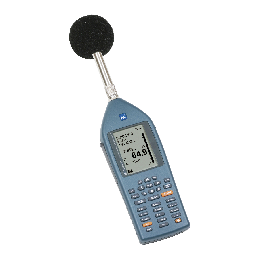
A sound level meter with built-in real
time analyser capabilities complying
with international instrument stand-
ards. Parallel octave fi lters are stand-
ard (optional in some markets), but
the impressive list of optional exten-
sions include third octave fi lters and
statistics in every frequency band,
multispectrum,
reverberation
measurements, and recording for the
measured sound. The instrument logs
level vs. time (optional) and when it is
equipped with multiple time constants
and the enhanced profi le extension, a
multitude of functions is logged simul-
taneously. The more than 120 dB dy-
namic range eliminates the need for
range setting. A large memory, SD-
card and high-speed data transfer
rates complete a user-friendly solution.
nor140
SOUND ANALYSER
time
Advertisement
Table of Contents

Related Manuals for Norsonic nor140


Summary of Contents for Norsonic nor140
- Page 1 The more than 120 dB dy- namic range eliminates the need for range setting. A large memory, SD- card and high-speed data transfer rates complete a user-friendly solution. nor140 SOUND ANALYSER...
- Page 2 Norsonic AS reserves the right to amend any of the infor- mation given in this manual in order to take account of new developments.
- Page 3 Instruction Manual Instruction Manual Finding the information you need Thank you for choosing Norsonic! The Nor140 has Note that the instruction manual describes a fully been designed to give you many years of safe, reliable equipped instrument. Your version may not have all the operation.
-
Page 5: Table Of Contents
Norsonic Nor140 Instruction Manual Contents Chapter 1 Introducing the Nor140 sound level meter ..............1 Modular design........................... 1 The functions available ........................1 The MODE and SETUP buttons ......................1 Global and Mode dependent parameters ..................1 The main features – an overview ......................2 Real time frequency analysis ...................... - Page 6 Contents Chapter 3 Calibrating the instrument ................... 16 When to calibrate ..........................16 No need to adjust the full scale setting .....................16 Carrying out the calibration .......................16 Chapter 4 Simple sound measurements ..................20 Setting the duration .......................... 20 Statistics ............................21 Instruments with time profile installed ....................22 Setting the time constant ........................
- Page 7 Norsonic Nor140 Instruction Manual after the measurement ....................... 34 Displaying the result tables ......................34 NC, NR and RC Mark II rating ......................38 Chapter 6 Basic time profile measurements ................40 Global vs. profile..........................40 Making measurements ........................43 Presenting the L(t) as a table ......................44 Chapter 7 Moving Leq ........................45...
- Page 8 Select USB or serial .......................... 77 NorXfer installation procedure ......................77 Installation of USB drivers for Nor140 ..................... 78 Quick Reference Guide – transfer and convert a measurement to Excel ........80 Virtual Instrument – Nor1036 Installation procedure ................ 82...
- Page 9 Norsonic Nor140 Instruction Manual Chapter 16 Signal input and output ....................83 Signal input ............................83 IEPE ..............................83 Noise output ............................. 84 RPM ..............................84 Signal output............................. 84 Chapter 17 Trigger..........................85 General ............................. 85 Setting the trigger condition ......................86 Manual trigger ..........................
- Page 10 Calculating the reverberation time ....................105 Measurement with noise excitation ....................105 Measurement with impulse excitation .................... 106 Measurement with swept sine excitation ..................107 Implementation in Nor140 ......................108 Excitation signals ..........................109 Minimum reverberation time possible .................... 109 Maximum reverberation times ......................109 Measuring according to the integrated impulse response method ..........
- Page 11 Norsonic Nor140 Instruction Manual Chapter 23 Sound Power ........................ 118 About sound power measurements ....................118 Rectangular parallelepiped ......................119 Hemispherical measurement surface .....................119 Hemispherical microphone positions ..................120 Additional microphone positions ....................120 Parallelepiped measurement surface .....................122 Microphone positions ........................122 Additional microphone positions ....................122 Reducing the number of positions ....................123...
- Page 12 Contents Calculating the Airborne sound insulation according to the Engineering method ....... 139 Source room level ........................139 Receiving room level .........................140 Background noise ........................140 Reverberation time ........................141 Display of results ........................142 Spectrum adaptation terms ....................143 Alternative national standards....................143 Store and recall ..........................
- Page 13 RASTI and STIPA ..........................161 How is STIPA measured ........................162 CIS ..............................163 Units included in delivery ....................... 163 Software option for Nor140......................163 Excitation file - a zipped file ......................163 Excel sheet ............................ 163 Measurement overview ........................164 General instrument description ...................... 164 Selecting a loudspeaker for the excitation ..................
- Page 14 Making a measurement ........................171 Calibration ............................172 Corrections ............................172 Storing the result ..........................173 Specification for FFT ........................173 Chapter 27 Measuring vibration using Nor140 ................174 Introduction ............................174 Accelerometer ..........................174 IEPE-type ............................175 Charge type .............................176 Velocity and displacement ......................177 Chapter 28 Audiometer calibration ..................
- Page 15 Weighting networks ........................181 Filters ............................181 Level detector ..........................181 Time weightings and measured functions ..................181 Level distribution ..........................182 Indication range ..........................182 Self-noise levels ..........................182 Z-wide considerations .......................182 Measurement duration and resolution ................... 183 Timing accuracy ........................183 Measurement range ........................184 Power supply ..........................
- Page 17 SOUND ANALYSER...
-
Page 19: Introducing The Nor140 Sound Level Meter
The spectral weighting functions A- and C- or Z-weight- Modular design ing are available for all functions including the L The Nor140 comes with an extensive set of functions PEAK The Z-weighting as specified in IEC 61672-1 available in its basic version. Many other functions are replaces Lin or Flat as these have not been properly available as optional extensions. -
Page 20: The Main Features - An Overview
Introduction Frequency analysis. When fi tted with the frequency analysis extensions the Nor140 can make real time frequency analysis in octaves or third-octaves. The functions measured are the equivalent level, the maximum level and the minimum level. The frequency range is 0,4 Hz to 20 kHz and thus covers both the audio and the vibration range. -
Page 21: Real Time Frequency Analysis
Units without filters will The two bandwidths share the type of functions calculate the broadband values (A- and C- or Z- measured. In a single frequency analysis the Nor140 weighted values). As usual, this is an optional feature measures: so if you don’t need it, you won’t have to pay for it... -
Page 22: Time Profile Measurements
Introduction Statistics. Adding option 4 to your Nor140 will expand Provide details – maintain overview. The level vs. your frequency analysis to even calculate the statistical time feature is the tool you need for detailed analysis level distribution for each frequency band measured! of the time profile. -
Page 23: Multispectral Measurements
No problem! The time profile extension can be expanded into the enhanced profile extension – our option 7 for Source coding the Nor140. Order it when you purchase your Nor140 Have you ever made a measurement where you later or later, if that suits you better. -
Page 24: Recording The Sound
But, you don’t need to attend the measurement optional and hence often referred to as options. In sessions all the time. In fact, the Nor140 is able to do a this way you do not have to pay for features you’re not lot on its own. -
Page 25: Check Which Extensions Are Installed
IEPE – Integral Electronics Piezoelectric is the generic term for transducers (accelerometers and microphone preamplifiers) using constant current supply for the build-in electronics in the transducer. Norsonic has chosen to use this abbreviation in our literature and products. Other abbreviation for the same is ICP®, DeltaTron®, ISOTRON®, CCLD, PIEZOTRON® and CCP. - Page 26 Introduction • Audio recording resolution and speed. • Pre-trigger on the audio recording. If possible, set it equal to or lower than 5 sec. Above 5 seconds, the pre-trigger goes into another mode, where the workload is the same as if a continuously audio re- cording was performed.
- Page 27 The options available. The below list was complete and exhaustive by the time of printing of this User Guide. However, constant improvements will normally result in new extensions becoming available on a regular basis. Check with your local Norsonic distributor or the factory for an update on this matter. and L...
-
Page 28: Chapter 2 Taking A Closer Look At The Instrument
If you use rechargeable batteries, these will not be recharged if The Nor140 comes with four AA batteries (1.5 V each). you connect the Nor140 to an external power supply. Battery lifetime is typically 8–12 hours (depends on measurement mode and brand of batteries). -
Page 29: Low Voltage Situations
START key had been pressed. If powered from internal batteries and left un- Battery voltage attended and unoperated, the Nor140 will switch itself Battery voltage is presented graphically as f(t). Press off after ten minutes. However, this does not apply if... - Page 30 Observe the following general guide- exposed to polarisation voltage. It will regain lines applicable to every Nor140 menu: its initial sensitivity shortly after the polarisation volt- age is no longer applied. A conventional cartridge •...
-
Page 31: Marks On The Lower Line Of The Display
Norsonic Nor140 Instruction Manual Screw only Microphone Marks on the lower line of the display finger tight! cartridge You may find the following marks on the lower line: Default cartridge is Microphone designed for 200 V The signal strength is indicated as a level in... -
Page 32: The Input Menu
• 1214/1216/1217 – Horizontal direction. This mode The input menu is used when connecting any of the outdoor mi- Nor140 supports various sensors. The default is the crophones Nor1214, Nor1216 or Nor1217 with the supplied microphone and preamplifier combination sound propagating in the horizontal direction. Typi- Nor1225/1209. - Page 33 Norsonic Nor140 Instruction Manual The front panel keys of the Nor140 Increment and decrement a parameter setting Leave a menu putting changes into effect Cursor keys to navigate in the menus Stop a measurement and to operate the graph cursors...
-
Page 34: Chapter 3 Calibrating The Instrument
No need to adjust the full scale setting measuring instruments are, in general, as stable as Since the Nor140 has a 120 dB dynamic range sound calibrators. However, measuring microphones (10–130 dB SPL), the 80 dB bar graph range is a are very delicate devices designed to fulfil very rigid display limitation only. - Page 35 Norsonic Nor140 Instruction Manual 5 Set the sensitivity. To set the sensitivity correctly 1 Mount the calibrator onto the sound level meter. Mount the sound calibrator onto the microphone as use the INC and DEC keys while at the same time shown to the right.
- Page 36 You may either set the sensitivity to the sound calibrator for verification of the sound combined value for the microphone and level meter Nor140 is the Norsonic Nor1251 the microphone preamplifier, or split the with a nominal sound pressure level of 114,0 dB @ sensitivity in one for the microphone and 1kHz.
- Page 37 (also called SysCheck). Pin 1 on the microphone input socket is able to supply a known voltage signal to the Norsonic Preamplifier Nor1209 (see Chapter 28 for details). By enabling this constant voltage signal, the entire measurement chain includ- ing the microphone is tested, and the display will show the corresponding measured value in dB.
-
Page 38: Chapter 4 Simple Sound Measurements
Simple sound measurements Simple sound measurements The Nor140 may still be used as a simple sound level Navigating in the menus. Observe the meter. The only thing you really need to set up is the following general guidelines applicable to... -
Page 39: Statistics
100 samples. You will need at least 100 samples to be able to calculate the 1% percentile. Going to measure very high levels? As an optional extension the Nor140 is able Likewise, for the 0,1% percentile the minimum to measure very high sound pressure levels time required will be 100 seconds. -
Page 40: Instruments With Time Profile Installed
The Z spectral weighting circuitry is flat within weighting and is independent of the setting. at least 16Hz to 16kHz (in the Nor140 it extends far To set the time constant press the TC key until the beyond that) and is defined in the International required time constant appears in the display. -
Page 41: Making A Measurement
Norsonic Nor140 Instruction Manual Making a measurement To resume a terminated measurement: • To resume a terminated measurement press the To start a measurement: PAUSE/CONT key. Upon resuming the instrument • Press the key. The in the display indicates will go on measuring until the total measurement START that a measurement is running. -
Page 42: Resuming An Ended Measurement
Chapter 4 Simple sound measurements ily halt the measurement until the PAUS/CONT key is pressed again. Dependant on the set back erase time, Pausing deletes up to 20 seconds of the last the last acquired data will be erased data. If you don’t want this, use and then STOP If the measurement has been running for less... -
Page 43: Displaying The Result Tables
Norsonic Nor140 Instruction Manual back to READY mode. The SPL will now be displayed Units configured for the again. German-speaking markets If you choose not to store the data (i.e. you did press If also equipped with L and T... -
Page 44: Statistics - Displaying The Percentiles
Chapter 4 Simple sound measurements refrain from that, we store just eight percentiles instead. Seven of them are fixed and one is user-editable. Displaying the result table using the other Your user-editable percentile can be set to anything spectral weighting function in the range 0.1–99.9 %, both extremes included. -
Page 45: Displaying The Percentiles Table
ENTER Storing the acquired data percentile. The Nor140 has a large, non-volatile memory to hold To terminate the editing process press the (end- the measurements. The memory structure resembles right key). The corresponding percentile value will... -
Page 46: User Defined Table
Chapter 4 Simple sound measurements User defined table The user may compose a user defined numeric table consisting of just the needed parameters for a given application. A typical task is a table consisting of only LAeq and Peak C. The parameters is selected in SETUP >... -
Page 47: Chapter 5 Frequency Analysis
Instruction Manual Frequency analysis Instruments without the multispectrum extension (op- As an optional extension 1, you may have your Nor140 tion 8) are not able to capture the spectra as a func- equipped with parallel octave band filters. By add- tion of time. -
Page 48: Statistics
Cf. Enhanced time profile measurements, Basic standard IEC 61672-1. time profile measurements and Multispectrum meas- The Nor140 can make use of two of the three urements for details on logging the level vs. time with spectral weighting functions simultaneously – viz. A- or without the spectrum as a function of time. -
Page 49: Finding The Energy Level Over A Part Of The Frequency Range
Going to measure very high levels? frequency of interest and the calculated Leq value for As an optional extension the Nor140 is able to meas- this frequency range will be displayed in the tabular ure very high sound pressure levels without chang- result picture as LΔeq. -
Page 50: Switching To Displaying The Spectrum
Chapter 5 Frequency analysis Making a frequency analysis As long as the frequency mode has been activated, frequency analysis will be made To start a frequency analysis measurement: during every measurement. This means • Set the measurement duration. that the instrument will combine a “traditional” sound level meter measurement and a real time frequency •... -
Page 51: Resuming An Ended Measurement
Norsonic Nor140 Instruction Manual The measurement has now ended successfully, To display other functions measured, as opposed to if you press the stop key to forcefully • Use the FUNC key. For the German-speaking terminate an ongoing measurement. markets these functions will include L... -
Page 52: Displaying The Functions Measured
Chapter 5 Frequency analysis The measurement time elapsed counter will be up- However, since the frequency analysis is made in dated to reflect the back erase time. The statistics buff- parallel with the traditional (A- and C- or Z-weighted) ers (optional extension) as well as all other measured sound level measurement, the broadband peak parameters will be updated accordingly. - Page 53 Norsonic Nor140 Instruction Manual Instruments configured for the German- The L and T are not accessible PEAK Max5 speaking markets will measure L (with I when the spectrum is displayed! time constant) and T (with F time con- Max5 stant) in addition – see below.
- Page 54 Chapter 5 Frequency analysis Displaying the result tables Displaying the result tables To switch between A- and C- or Z-weighted values, Sound level meter use the NETW key display mode Statistics is optional Units not configured for the German speaking markets will have tables without I Leq (LeqI) and Tmx5 values...
- Page 55 Norsonic Nor140 Instruction Manual Editing the user-defined percentile Missing percentiles? There may be per- To enable the editing, the instrument must display centiles that fail to produce values in the the percentiles table. In the percentiles table press table. This is because you have not meas- key (the end-left key) to enable this.
-
Page 56: Nc, Nr And Rc Mark Ii Rating
The NC – Noise Criteria, NR – Noise rating and RC Noise Criterion - NC - were established in U.S. for rating Mark II – room criteria are supported in the Nor140, indoor noise and noise from air-conditioning equipment all returning a single dB value based on frequency etc. - Page 57 Norsonic Nor140 Instruction Manual and from 31.5 to 8000 Hz for the NR, and a tangency rating procedure. The criteria curves define the limits of octave band spectra that must not be exceeded to meet occupant acceptance in certain spaces.
-
Page 58: Basic Time Profile Measurements
25 ms steps (but in 1 second steps above 1 second ment described in the chapter Simple sound meas- period length). urements. If your Nor140 is equipped with the multi- The logged profile may be transferred to a PC for spectrum extension, you may log the spectrum as a further analysis. - Page 59 Norsonic Nor140 Instruction Manual The measurement duration setup menu The time profile display The Δ indicates Display top scale profile (global is Total (global) duration indicated by a Σ) of measurement. Selected resolution Spectral weight- Graph cursor. No. of periods with...
- Page 60 Chapter 6 Basic time profile measurements Displaying the result tables To switch between A- and C- or Z-weighted values, use the NETW key Sound level meter display mode Statistics is optional Units not configured for the German speaking markets will have tables without I Leq (LeqI) and Tmx5 values.
-
Page 61: Making Measurements
0 - 20 s) acquired immediately before the pause Making measurements to be erased. This applies to the global measurement, All you need to do to set up the Nor140 to expand the but not to the profile. measurements to also include the time profile is to de- Assume you have set up the measurement to also fine the time resolution. -
Page 62: Presenting The L(T) As A Table
Chapter 6 Basic time profile measurements Presenting the L(t) as a table To start the time profile measurement: Numerical presentation of the acquired data works • Press START. even here. Press TBL while in Δ (profile) mode to pro- duce the table. This can be done during, as well as af- To switch to see the time profile: ter, a measurement. -
Page 63: Chapter 7 Moving Leq
A useful addition to the measurement capacity of the PS! The Moving Leq function is available Nor140 is to be able to follow the noise level over a for instruments equipped with level vs. time certain window in time after a certain threshold level - option 6 as a minimum has been reached. - Page 64 Chapter 7 Moving Leq The displayed values MLeq1 and MLeq2 give you the Leq over the “moving windows” with the set PS! If you only need to follow one event, ie. duration while the measurement is running, in the Period 1, just fill in 0 (zero) for in the field for duration for Period 2.
- Page 65 Norsonic Nor140 Instruction Manual Using NorXfer, the Moving Leq values are reported as follows in the Global sheet:...
-
Page 66: Enhanced Time Profile Measurements
Chapter 8 Enhanced time profile measurements Enhanced time profile measurements The optional extension 7 – enhanced time profile lets 3 The set up for both the A-weighted and the C- or Z- you select the functions to be measured as a function weighted functions and filter bands, if available, are accessible from within this menu. -
Page 67: Copy The Setting To Prnt/Xfer
Norsonic Nor140 Instruction Manual Functions like L and L are measured To produce the transfer functions setup menu: PEAK during each period. The SPL, however, is sampled at • Press SETUP > 1 > 9 > 2 the end of each period. - Page 68 Chapter 8 Enhanced time profile measurements The enhanced profile offers a time resolution (period length) down to 50 ms! Between 50 ms and 1 s No back-erase in profile pause mode. The resumption of a paused measurement the resolution is adjustable in 25 ms steps. Above 1 s will cause up to 20 seconds (adjustable the step size is 1 s as is the case for the basic profile.
-
Page 69: Measuring In Enhanced Mode
Norsonic Nor140 Instruction Manual Measuring in enhanced mode The enhanced time profile mode is similar to the basic time mode and should thus be regarded as an add-on to the instrument’s basic functionality. This means that the features available while measuring – described in the chapters Simple sound measurements and Frequency analysis apply even here. -
Page 70: Adding Markers To A Measurement
Chapter 9 Adding markers to a measurement Adding markers to a measurement Have you ever made a measurement where you later Example: In a traffic noise measurement a bus pass- found out that you desperately need to identify the ing may be identified by the digit “1”, while trucks may cause of the level? be identified by “2”, unexpected vehicles by “3”... -
Page 71: Other Markers Inserted By The Instrument
Norsonic Nor140 Instruction Manual Other markers inserted Marker overview by the instrument M1 marker M2 marker As discussed in the side bar No back-erase in M3 marker profile mode (in chapter 7) the single marker “P” is M4 marker (toggle) -
Page 72: Chapter 10 Multispectrum Measurements
Chapter 10 Multispectrum measurements Multispectrum measurements The combination of filters (minimum option 1) and time Setting up for multispectrum profile mode (minimum option 6) takes the instrument Multispectrum measurements can be made based to greater sophistication by introducing multispectrum on basic- as well as enhanced time profile extensions measurements. -
Page 73: Making Multispectrum Measurements
Norsonic Nor140 Instruction Manual Use the NETW key to switch between A-weighted To set up for multispectrum measurements functions, the C-/Z-weighted functions and the fi lter (enhanced time profi le): band functions. Remember that the fi lter functions 1 Set up the duration and resolution must be turned on (using SETUP >... - Page 74 Chapter 10 Multispectrum measurements To move the cursor along the time profile axis: To see the spectrum of another moment in time: 1 Make sure the display shows the time profile (level 1 Make sure the instrument is in profile mode and that vs.
-
Page 75: The Result Tables
Norsonic Nor140 Instruction Manual To see the level vs. time (the profile) graph of an- To produce the result tables in multispectrum other frequency band: mode: 1 Make sure the display shows a time profile (level vs. 1 Press TBL once to produce Table 1 and again to time). - Page 76 Chapter 10 Multispectrum measurements Global mode Profile mode Multispectrum mode Optional, requires statistics Global frequency mode...
- Page 77 Norsonic Nor140 Instruction Manual The key pressing sequence is also illustrated in the Fig. overleaf, while operating details are provided below. Both tables are accessible during measurement, you can even start a measurement from within any of the tables! All functions available for a profile measure- ment apply even here.
-
Page 78: Chapter 11 Engineering Units
Due to the high dynamic measurement range for When values are transferred to a PC, the dB format Nor140, the measured values displayed in linear units will be used independent of the setting in the will vary over more than six decades. By changing the instrument. -
Page 79: Relation Between Db And Eu
The graphical display is left unchanged The logarithmic dB scale is a scale relative to a com- when engineering units are selected. mon reference value. In the Nor140 instrument the ref- erence value is always 2x10 corresponding to the common reference value for sound pressure levels: 20 µPa. - Page 80 Chapter 11 Engineering Units Example 1 Example 2 A microphone with preamplifier has a sensitivity of 50 The combination of an accelerometer and an amplifier mV/Pa or 0.05 V/Pa. The SI-unit pascal [Pa] is now has a sensitivity of 20 mV/ms .
-
Page 81: Chapter 12 Memory Handling
Memory structure Example 3. The memory can hold approximately The memory structure of the Nor140 is quite similar to 1 2 500 000 samples of L(t) when only one function is that of a PC. They both have folders and files. Howev- logged (requires the enhanced profile extension). -
Page 82: Select The Device For Storing
Chapter 12 Memory handling Format Select the device for storing Always format the SD-card in the instrument before You may select either the internal memory or the op- first time use. Formatting a card is also the fastest way tional SD-card as the location for storing data. You for deleting all data on the card. -
Page 83: General
Norsonic Nor140 Norsonic Nor140 Instruction Manual Instruction Manual Global parameters This measurement has been The following parameters are global and adjustment in stored as fi le No. 7 in today’s one mode of operation for the instrument will be valid... -
Page 84: Mode Dependent Parameters
Chapter 12 Memory handling Mode dependent parameters When a measurement is stored, a genuine identity number (instrument ID) is also stored with the measure- The parameters, which are not global, can be adjusted ment results. This is not visible in the instrument itself, in one mode of operation for the instrument without af- but post processing or measurement control software fecting the value of the same parameters in another... -
Page 85: Standard Set-Up
Norsonic Nor140 Norsonic Nor140 Instruction Manual Instruction Manual Standard set-up Retrieving stored setups and data Some standard set-ups are delivered with the instru- Folders Storing device ment. You may use one of these set-ups as a start- Once you’ve pressed the... - Page 86 Chapter 12 Memory handling Standard set ups for the different sound level meter modes Name: Description / Use: 0001L Normal sound level meter mode measurements 0002T Normal level versus time mode measurements 0003F Simple frequency analysis with 1/1 octave resolution 0004F Simple frequency analysis with 1/3 octave resolution 0005M...
-
Page 87: Clearing Files And Folders In The Memory
Norsonic Nor140 Norsonic Nor140 Instruction Manual Instruction Manual Clearing folders or the entire memory Clearing files and folders in the memory To clear a folder: To delete files and folders in the directory: • Select it using the cursor keys and press Press ENTER. - Page 88 Chapter 12 Memory handling Keeping track of the measurement mode the file was stored in. The different modes are indicated in the file list as follows: All file names (i.e. file numbers) have a letter as suffix. This letter indicates the measurement mode: means frequency analysis, but no profile means that the file contains a simple global...
-
Page 89: Automatic Storing Of Data And Noise Monitoring
– typically ers leave more of the job to the measuring instrument 3–4 seconds per individual measurement. itself. The Nor140 can be used with success in both If this lag is unacceptable for you, we recommend types of systems. -
Page 90: Synchro - An Example
Going to measure very high levels? Press , to unlock the keyboard As an optional extension the Nor140 is able to measure very high sound pressure levels Note that the instrument must show the sound level without changing the microphone cartridge meter display for this to work (in this display the –... -
Page 91: Setting The Storage Mode
SD-card. load acquired data) Other setup aspects The setup of Nor140 will be found in this manual, while The setup for a monitoring job will depend on the task, all accessories can be found in a separate leaflet or at so no absolutes can be given here. -
Page 92: Chapter 14 Making Hardcopies
(IO/Print). SETUP > 1 > 2 design of the printer drivers used in Nor140 may not be true the day you read this. Output from the Nor140 is Set the serial interface port to RS232, set a baud rate purely numerical, hence almost any numerical printer your printer can handle –... - Page 93 Norsonic Nor140 Instruction Manual To set which functions to print out: Two printout examples, a profile and a sound power meas- urement output Press (Depend on options). SETUP >1 >9 >1 Use the cursor keys to navigate and the 1”...
-
Page 94: Chapter 15 Transfer Of Data To A Pc
(RS232) or an USB-cable (USB). The quickest way however is to store the data on the SD-card and move the card to a PC for loading the data. Norsonic supply different programs for controlling the instru- ment and analysis of the measured data. Contact your local Norsonic distributor for more information as the number of programs is steadily growing. -
Page 95: Select Usb Or Serial
To transfer measured data from the Nor140 to a pany, name, email and product, so that we will be able PC by serial interface you will need a Nor1441 cable to contact you if this should be necessary. -
Page 96: Installation Of Usb Drivers For Nor140
Installation of USB drivers for Nor140 The driver consists of two parts, and there will be a The Nor140 device driver is normally distributed and dialog-window asking if you would like to install the installed with other Norsonic software. It may also be device software for both of them. - Page 97 Norsonic Nor140 Instruction Manual When the device driver installation is complete, the fol- lowing dialog-window will appear. Click “Finish”. After you have plugged in the Nor13x/Nor14x for the fi rst time, it may take some time (less than a minute) before Windows “activates”...
-
Page 98: Quick Reference Guide - Transfer And Convert A Measurement To Excel
The menu below appears. Select either “local (SD card) (Nor140) or the appropriate USB port (Nor13x and Nor140), dependent on where the data is stored The instrument will appear as shown below. Double- click on the instrument in the right frame to expand the Expand “My Measurement”... - Page 99 Norsonic Nor140 Instruction Manual An Excel file is generated that contains all the meas- ured values. Measurements in rows, values in columns.
-
Page 100: Virtual Instrument - Nor1036 Installation Procedure
“Snapshot”. The setup for the picture format and where to store the picture is found in the “File” menu. The fig- www.norsonic.com/release. ure below shows the setup. The screen picture may be stored as Bitmap (bmp), Jpeg or Tiff. The Tiff-format is Follow the procedure given by the installation program. -
Page 101: Signal Input And Output
These types of transducers are pressing SETUP > 1 >4 (Press INC if “STANDARD” often used for measurement of acceleration. Nor140 is is not displayed), the signal input is an AC-coupled able to measure down to 0,4 Hz, and will therefore be input terminal with an input impedance of more than well suited for such applications. -
Page 102: Noise Output
The RPM functions are turned on and off via the SETUP 9 selection. Signal output The sound level meter Nor140 is equipped with a sig- nal out terminal. The signal is a replica of the micro- phone- or input signal. You may use the terminal for listening to the measured signal, or you may use it for other purposes. -
Page 103: Chapter 17 Trigger
Norsonic Nor140 Instruction Manual Trigger The measurement may also be initialised by a trig- General ger signal from an external device. When started, the Noise monitoring often requires operating a sound measurement will last as long as set up by the meas- level meter out in the field for unattended long-term urement duration parameter. -
Page 104: Setting The Trigger Condition
Chapter 17 Trigger or seconds. Modify the value by using the INC and Setting the trigger condition DEC key on the right side of the display, or key in a When the instrument is installed with the trigger option, numeric value followed by pressing ENTER. When the the Trigger Menu is found in the Setup menu. -
Page 105: External Trigger
Norsonic Nor140 Instruction Manual External trigger Level above-trigger The external trigger function is selected by moving The level above-trigger function allows a measure- the field cursor to the field “External” and pressing ment to be started as soon as the level in the specified network or filter band is above a specified threshold. - Page 106 Chapter 17 Trigger If you set the repeat measurement function (Press SETUP > 1 > 1), the instrument will start a new meas- urement after the first is finished and wait for the trigger condition to be satisfied again. If you want to interrupt a waiting-for-trigger opera- tion, press the STOP key.
-
Page 107: Recording The Sound
Dependent on the selected Recording gain quality of the selected storing format, the signal may The Nor140 has a large dynamic range – exceeding also be used for further analysis. 120 dB. This means that if you try to play back the... -
Page 108: Recording Duration
Chapter 18 Sound recording 99 seconds. This allows the recording to start up to 99 Recording duration seconds before you pressed the record button or the The duration of a recording can be set from 1s in one trigger condition was fulfilled. second steps up to 9999 s (close to three hours). -
Page 109: Setup For A Recording
Norsonic Nor140 Instruction Manual Manual trigger Setup for a recording Set the external and level triggering to “OFF”. Select Press SETUP > 8 and menu for specifying the record- the time delay between the trigger command and the ing will be shown. -
Page 110: Level Above-Trigger
NorXfer (Nor1020) for taking care of the menu struc- ture. When the result is analysed with the PC-program Trigger threshold NorReview (Nor1026) the measurement and the sound recordings are automatically coupled. Please contact your Norsonic representative for further information. Record time... -
Page 111: Insert A Reference Tone As A Recording
Norsonic Nor140 Instruction Manual The preset type, gain and excitation time of the Insert a reference tone as a recording reference tone are edited in the same menu. The type When listening to a recording, it may be required to is either PINK noise or a SINE wave. -
Page 112: Chapter 19 Reference Spectrum
Chapter 19 Reference Spectrum Reference Spectrum General Frequency mode menu The Reference Spectra feature is used for compari- son of any measured frequency spectrum with a pre- selected user defined spectrum. It functions both on 1/1-octave and 1/3-octave spectra. The measured spectrum may be compared to an upper limit, a lower limit, or both an upper and a lower based on user defined boundary spectra. -
Page 113: Using A Previously Measured Spectrum
Norsonic Nor140 Instruction Manual Using a previously Reference curve selection menu. measured spectrum Select one of the four possible Reference curves as indicated above, press the RECALL key and use the normal memory operation to choose any previously saved measurement as the new Reference Spectrum. -
Page 114: Editing A Selected Reference Spectrum
Chapter 19 Reference Spectrum Editing a selected “Go / NoGo” Quality Control feature Reference Spectrum The Reference Spectrum feature may be used to give a “Go” or a “NoGo” output signal in quality control ap- Use cursor keys to move the field indicator in row with the frequency band to be edited. -
Page 115: Digital Output Lines
Norsonic Nor140 Instruction Manual In cases where all frequency bands must be above Note! When using the relay box Nor268, or below the Reference Spectrum in order to get the desired “Go/NoGo” status, a selection of the respec- Digital I/O 2, DO-2 must be set to GO in the Digital I/O menu - SETUP 1 >... -
Page 116: Chapter 20 Noise Generator
Chapter 20 Noise generator Noise Generator Selecting noise type and level General Press SETUP and either 3 or 7 (dependant on operat- By activating option 10, access to an internal signal ing mode) for selecting noise set-up menu. A dialogue generator is gained. -
Page 117: Adjustments For Reverberation Measurement
This can be difficult due to acoustical proper- ties in the room and due to the frequency response of the excitation equipment in use. For this purpose, the Nor140 offer a simplified equalizer on the signal output. -
Page 118: Chapter 21 Compensation And Correction
Instrument menu Sometimes the accuracy of a measurement can be increased if the measurement is corrected or compen- sated for other known effects. Nor140 has the ability to make corrections related to • Use of windscreen • Measurement of random incidence sound or diffuse sound fields •... -
Page 119: Preamplifier Correction
Norsonic Nor140 Instruction Manual Preamplifier correction Measurement of low sound levels When the microphone is mounted on the preamp- When measuring very low levels, the indicated level lifier, a very small fraction of the signal is “lost” in the may be influenced by the self-noise of the instrument. -
Page 120: Measuring The Self-Noise
Chapter 21 Compensation and correction When the self-noise correction is active a “S” is dis- played in the lower line of the display. Linearity error without and with correction Measuring the self-noise The self-noise of a sound level meter is the indication on the meter when the instrument is placed in a quiet place where the actual sound pressure level is consid- erably (20 dB) less than the self-noise. - Page 121 Norsonic Nor140 Instruction Manual from 200 V to about 70 V. The microphone sensitivity will then be reduced by 10 dB and the instrument will Marks on the lower line of the display be able to measure peak signals up to 150 dB.
-
Page 122: Chapter 22 Reverberation Time Measurements
Chapter 22 Reverberation time measurements Reverberation time measurements The optional extension 9 for the Nor140 permits meas- What is reverberation time? urements of the reverberation time. The reverberation Assume that you switch on a sound source in a room time is simultaneously measured in every frequency equipped with a microphone system. -
Page 123: Calculating The Reverberation Time
Norsonic Nor140 Instruction Manual noise method if option 10, internal noise generator, is A plot of the sound pressure level versus time will additionally installed. An external noise signal can also in general contain information on the obtained station- be used. The integrated impulse response method... -
Page 124: Measurement With Impulse Excitation
Chapter 22 Reverberation time measurements Measurement with impulse excitation According to the Schroeder methods, the results may be obtained from processing of the impulse re- M.R. Schroeder [1] has shown that the expected decay sponse itself. in one particular observation point may be obtained When a room has been excited by stationary white/ without averaging by processing the impulse response pink noise for a time sufficient to obtain stationary con-... -
Page 125: Measurement With Swept Sine Excitation
Norsonic Nor140 Instruction Manual Due to the fact that the running time, t, is the lower Measurement with swept sine excitation start point for the integration, the operation of the for- New technology and the use of digital signal proces-... -
Page 126: Implementation In Nor140
Chapter 22 Reverberation time measurements Implementation in Nor140 Swept Sine excitation. When the Swept Sine method is used, the wide band impulse response is calculated. The instrument can be set to measure reverberation This signal is fed through the filter section as if it was a times with various maximum lengths. -
Page 127: Excitation Signals
Norsonic Nor140 Instruction Manual Excitation signals Minimum reverberation time possible Impulse excitation. Excitation for the integrated im- The frequency analysis in the form of 1/3- and 1/1- oc- pulse response method may be any impulsive, broad- tave filters sets a lower boundary for the reverberation band source with suitable low directivity. - Page 128 Chapter 22 Reverberation time measurements Minimum reverberation times Lower limit Lower limit Frequency 1/3-oct 1/1-oct 50 Hz 0,60 63 Hz 0,48 0,24 80 Hz 0,38 100 Hz 0,30 125 Hz 0,24 0,12 160 Hz 0,19 200 Hz 0,15 250 Hz 0,12 0,06 315 Hz...
-
Page 129: Measuring According To The Integrated Impulse Response Method
Norsonic Nor140 Instruction Manual Make sure the excitation type is set to Impulse. Press The level above which trigger will take place (pro- SETUP > 2 and move the cursor filed to excitation type vided that a level transition takes place) is shown as (Ex.type) and select “IMP”... - Page 130 Chapter 22 Reverberation time measurements The letter R in the upper left corner of the display in- During the measurement, the instrument will show dicates that the instrument now is in reverberation time the remaining measurement time. The total measure- mode.
-
Page 131: Measuring According To Interrupted Noise Method
Norsonic Nor140 Instruction Manual to scroll along the time axes. You may compress the In the set up menu you will find the mode specific set display by pressing the key . The factor for compres- up features. sion is displayed as C=2 etc. In a similar way the graph may be expanded by pressing the key . - Page 132 Chapter 22 Reverberation time measurements Press the START key. The instruments switch on the noise for the selected excitation time and present the Reverberation Table W-mark. The logging of the level starts when the noise is switched off and the run indicator R is displayed. The instrument will measure for a number of seconds dependant on the maximum expected reverberation time (from 5 to 40 seconds) and...
-
Page 133: Measuring According To Interrupted Noise Method With External Noise
Norsonic Nor140 Instruction Manual After the measurement you may inspect the level Push ENTER. Use SETUP > 2 to set Ex.type to “EXT”. profile of the measured signal by pressing the Push ENTER twice. key Σ↔Δ. Note that the logging of the profile starts when... -
Page 134: Measuring According To The Swept Sine Method
Chapter 22 Reverberation time measurements The instrument will measure for a number of Measuring according to the seconds dependant on the maximum expected Swept Sine method reverberation time (from 5 to 40 seconds) and The instrument has to be set in a special mode of oper- count down to 0 to indicate how much is left of the ation in order to measure the reverberation time. - Page 135 Norsonic Nor140 Instruction Manual Press SETUP > 2 and move the cursor filed to exci- The calculation of the reverberation times is auto- tation type (Ex.type) and select “IMP” by the use of matically performed and the result values are shown the INC or the DEC key.
-
Page 136: Chapter 23 Sound Power
Sound power may be calculated from sound pressure In this case the measurement distance d is the levels using the Nor140 equipped with option 15. The distance between the measurement surface method is described in ISO 3746 acoustics – determi- and the reference box. -
Page 137: Rectangular Parallelepiped
Norsonic Nor140 Instruction Manual Rectangular parallelepiped For the rectangular parallelepiped reference box there The figures shows the characteristic dimension d are three possible configurations as shown in the Fig the different locations of the source under test. to the left. -
Page 138: Hemispherical Microphone Positions
Chapter 23 Sound power The radius of the hemisphere should be one of the The Fig. below left shows the location of four key mi- following values (in metres): 1, 2, 4, 6, 8, 10, 12, 14 or crophone positions, each associated with equal areas 16. - Page 139 Norsonic Nor140 Instruction Manual Microphone Array on the Hemisphere One reflecting plane Measurement surface Reference box 0.89r Measurement surface 10 20 Two reflecting planes 14 15 NB! Dimensions in metres Reference box NB! Dimensions in metres Key microphone positions Additional microphone positions...
-
Page 140: Parallelepiped Measurement Surface
Chapter 23 Sound power Parallelepiped measurement surface Microphone positions The microphone positions lie on the measurement The measurement distance d is the perpendicular surface, a hypothetical surface of area S enveloping distance between the reference box and the meas- the source whose sides are parallel to the sides of the urement surface. -
Page 141: Reducing The Number Of Positions
Norsonic Nor140 Instruction Manual the noise from a large source is radiated only More than one reflecting plane from a small portion of the source, e.g. the For a source installed adjacent to more than one re- openings of an otherwise closed machine. - Page 142 Chapter 23 Sound power Example of a measurement surface and microphone posi- tions for a small machine… …and an example of microphone placement for a larger machine. Details on the microphone posi- tioning can be found in the ISO 3746. Microphone placement with four …and three microphones for floor- microphones for floor-standing ap-...
-
Page 143: Sound Power - Acoustic Environment Requirements
Norsonic Nor140 Instruction Manual outside the near field of the sound source un- Sound power – der test. acoustic environment requirements A test area outdoors or an ordinary room will provide a For the purpose of the survey method (the method... -
Page 144: Specific Requirements
Chapter 23 Sound power Specific requirements = 10lg[1 + 4(S/A)] dB Examples of permitted reflecting planes outdoors in- clude compacted earth, artificial surfaces such as where concrete or sealed asphalt, while for indoor measure- ments, the reflecting plane is usually the floor. is the equivalent sound absorption area in the Take care to ensure that the reflecting surface does room at 1 kHz, in m... -
Page 145: Test Room Qualification Requirements
(in-situ), is the reverberation time of the room. rather than in a laboratory (in-vitro). If your Nor140 is equipped with the optional extension 9 reverberation time measurements, you may use this Making measurements to calculate the absorption as follows:... - Page 146 The background noise measurement display… The measurement control display…. Although the Nor140 Although only 8 (next) and lets you measure the...
- Page 147 Norsonic Nor140 Instruction Manual The environmental correction factor K accounts for the influence of undesired sound reflections from room boundaries and/or reflecting objects near the source under test. The magnitude of this environmental correction factor depends principally on the ratio of the sound absorption area A of the test room to the area S of the measurement surface. The magnitude does not depend strongly on the location of the source in the test room.
-
Page 148: Background Noise
Chapter 23 Sound power Measurement surface Note that the last measurement with individual The sound power calculation requires the operator to meas. for each pos, as well as setup of meas- select the correct measurement surface. urement condition, is retained even after leaving and re-entering the SP mode. -
Page 149: Sound Power Results
Based on the averaged sound pressure level of all the microphone positions, the measured background noise level and the selections and corrections made in the sound power setup menu, the Nor140 will display the final L To see the sound power calculation results: •... -
Page 150: Chapter 24 Building Acoustics
4 firmware of the Nor140. When equipped with the required program options, Additionally, there are possibilities for measurement Nor140 is well suited for measurement of building of the airborne and impact sound insulation in accord- acoustics in the form of measuring reverberation time ance with the French regulation. - Page 151 Norsonic Nor140 Norsonic Nor140 Instruction Manual Instruction Manual Building Acoustic Control Menu MODE In the rest of this manual we often talk about For measurement of facades, use “Airborne” as described in sections covering Facade insulation. BA for Building Acoustics At any stage –...
-
Page 152: Terms And Definitions For Airborne Sound Insulation
[m account. This is not required when calculating in accordance to the ISO Standards. The Nor140 is area of the partition between the source and re- originally designed for sound insulation calcula- ceiving room [m tions in accordance with the ISO Standards. -
Page 153: Terms And Definitions For Impact Sound Insulation
Norsonic Nor140 Norsonic Nor140 Instruction Manual Instruction Manual Terms and definitions for impact sound insulation The values are calculated for each frequency band. For and L , a single-number value is also calculated. The following terms are used in the display:... -
Page 154: Airborne Sound Insulation
Chapter 24 Building Acoustics The level measurements may be performed in the Airborne sound insulation normal mode of operation and stored for later process- ing, or alternatively, the measurements may be start- General ed from the calculation menu when the results are When airborne sound insulation between rooms is required for the calculation. -
Page 155: Calculating The Airborne Sound Insulation According To The Survey Method
Norsonic Nor140 Norsonic Nor140 Instruction Manual Instruction Manual Calculator screens Estimating the correction for the acoustic absorption Calculating the Airborne Sound insulation The field cursor automatically moves between the according to the Survey Method fields as values are entered. If you want to adjust any... - Page 156 Chapter 24 Building Acoustics otherwise impulse method has to be used. To start a measurement, press START when the field cursor is in Display of Survey Results the field for reverberation time marked “T”. Alternative- ly move the cursor to the “E” field at the end of the line and press ENTER to activate the “Estimate k:”...
-
Page 157: Calculating The Airborne Sound Insulation According To The Engineering Method
ENTER, or move the field cursor to “C” and ternational ISO 10052 Standard. Therefore, the Nor140 press ENTER for a calculator. The calculator allows offer this special version in a separate sub-mode. Se-... -
Page 158: Receiving Room Level
Chapter 24 Building Acoustics The averaged level L is obtained according to the fol- Background noise lowing formula where L is the result from each of the Also the average background noise level, Lb, can be N values: measured. Entering values for the background noise level is optional. -
Page 159: Reverberation Time
Norsonic Nor140 Norsonic Nor140 Instruction Manual Instruction Manual Reverberation time The acoustic losses of the receiving room used in the calculation may be obtained by measuring the rever- The correction is limited to maximum 1,3 dB corre- beration time or by recalling earlier measured values. -
Page 160: Display Of Results
Chapter 24 Building Acoustics Display of results When the required information has been entered, the Display of measurement result cursor will automatically be placed in the field for cal- culation of the final result. If you are satisfied with the entered values press ENTER, or if you want to make any correction, move the field cursor to the required field and enter the corrected values or press DEL to... -
Page 161: Spectrum Adaptation Terms
Alternative national standards As alternatives to the default ISO 16283-1 / ISO 717- 1 Standards, the Nor140 firmware version 4 offer two alternative national Standards for the calculation of the airborne sound insulation. This is the British Standard View the Criteria in the BA mode BS-ISO 140-4 which calculates the D’, Dn, DnT and R’... -
Page 162: Store And Recall
Chapter 24 Building Acoustics Store and recall tions measurements should be averaged. This may be obtained in the following way: You may store the result by pressing STORE. The file is Measure the level in the source and receiving room, automatically designated with the next free file number and L , and store the result. -
Page 163: Corner Measurement For Small Rooms
Noise Generator control screen ing Standard ISO 16283-1 requires additional meas- urements in the corner of the receiving room. These measurements are not possible with the Nor140 Build- ing Acoustic mode. However, by measuring the levels and reverbera- tion time in mode 1 and mode 2 respectively, these... -
Page 164: Impact Sound Insulation
ISO 10052. For other measurements more positions are required. Norsonic recommend the tapping machine Nor277. Calculating the Survey result Select the building acoustic mode and press 2 for Measurement of sound level “Impact”. -
Page 165: Impact Sound Insulation According To The French National Standard
ENTER, or if you want to make any correction, contains some special limitations compared to the in- move the field cursor to the required field and enter the ternational ISO 10052 Standard. Therefore, the Nor140 corrected values. offer this special version in a separate sub-mode. Se- When you move the field cursor to the field “Calc... -
Page 166: Calculating The Impact Sound Insulation According To The Engineering Method
Chapter 24 Building Acoustics 2. It is not allowed to use the pre-defined reverberation times based on the room criteria. The reverberation Display of measurement result times must be measured in the actual receiving room. 3. If the measured reverberation time for any frequen- cy band is outside the 0,4 –... -
Page 167: Background Noise
Norsonic Nor140 Norsonic Nor140 Instruction Manual Instruction Manual Background noise Display of results The average background noise level, L , is obtained in When the required information has been entered, the a similar way. cursor will automatically be placed in the field for cal- Entering vales for the background noise level is op- culation of the final result. -
Page 168: Alternative National Standards
Averaging levels from multiple tapping machine positions As alternatives to the default ISO 16283-2 / ISO 717- 2 Standards, the Nor140 firmware version 4 offer two When you measure the impact levels in many micro- alternative national Standards for the calculation of the phone positions as described and make the average airborne sound insulation. -
Page 169: Corner Measurement For Small Rooms
However, this can Partly re-use of be achieved by using two Nor140 sound level meters. previous measurements Please contact your local Norsonic office for further in- When making several sound insulations tests where ei- formation on such systems. -
Page 170: Noise Excitation
Nor280. Another alternative is to play a music-CD with recorded noise. Norsonic can supply a CD with the required excitation signal (Nor1033) The menu for airborne sound insulation is also used for facade measurements −... -
Page 171: Measurement Of Sound Level
Norsonic Nor140 Norsonic Nor140 Instruction Manual Instruction Manual Normally the loudspeaker is placed on the ground Measurement of reverberation time in a position, which makes the angle between the nor- See measurement of airborne sound insulation be- mal to the facade and the sound incidence close to tween rooms for further information. -
Page 172: Terms And Definitions For Service Equipment Measurements
Chapter 24 Building Acoustics Terms and definitions for service equipment Corner position Sound Pressure Level measurements The first set of values to be entered is the A- and C- weighted sound pressure level Lc in the apparent cor- The following terms are used in the display: ner with the hardest surfaces. -
Page 173: Reverberation Time
“T”. After the measurement you may mal mode of operation. inspect the resulting reverberation table by pressing the TBL key. The Nor140 will automatically make an average reverberation time based on the values for the Service equipment sound pressure 500Hz, 1 kHz and 2 kHz, and use this average value in levels –Engineering method... -
Page 174: Reverberant Position Sound Pressure Level
Chapter 24 Building Acoustics You are prompted to accept the recalled or meas- Reverberation time ured values as a part of the averaged result. Press The final set of values to be entered is the reverbera- ENTER (alternatively STORE) to accept or EXIT (al- tion times. - Page 175 Norsonic Nor140 Norsonic Nor140 Instruction Manual Instruction Manual • The averaged corner level Lc • The averaged reverberant field level Lr • The averaged reverberation time T • The averaged Lc plus Lr sound pressure level L • The calculated reverberation index k Use the FUNC key to scroll through the above mentioned function in order to display the desired values.
-
Page 176: Remote Operation From A Pc
Building Acoustic system can be of- 11 also extends the internal noise generator (option fered which allow the user to operate all Nor140 units in 10) to include band-pass filtered noise in addition to parallel. In such a combination, all Noir140 units must white and pink noise. -
Page 177: Swept-Sine Measurement Of Sound Level
1, 5 or 11 minutes respectively. Swept-Sine measurement of sound level The longer duration, the better S/N ratio is achieved. Upon connecting the Nor140 to the PC running the “Required S/N-ratio” is setting the acceptance ratio NorBuild software package with the CtrlBuild remote for the measured results. -
Page 178: Chapter 25 Speech Intelligibility By Stipa
Chapter 25 Speech Intelligibility by STIPA Speech Intelligibility by STIPA Development of STI Introduction – What is STIPA The basis for the STI-index is that the intelligibility of speech is largely based on the slow modulation of the strength of the sound pressure signal that acts as a Speech transmission index –... -
Page 179: Rasti And Stipa
Norsonic Nor140 Instruction Manual In order to fully take care of the effects of non-linearity, As seen from this formula, a limited signal-to-noise it is important that the basic signal being modulated is ratio reduces the modulation transfer function for all a noise signal with a high crest-factor, a spectral distri- frequencies. -
Page 180: How Is Stipa Measured
Chapter 25 Speech Intelligibility by STIPA The RASTI-method is in the current version of The STI value will be lower for speech levels below IEC 60268-16 obsolete. 50 dB and above 80 dB. The STIPA method uses a higher degree of modula- tion for each test frequency. -
Page 181: Cis
STIPA-option. installed on the sound level meter at a latter date. Please contact your local Norsonic dealer or the factory if you want your instrument upgraded with this Excel sheet option. -
Page 182: Measurement Overview
CD-player. When The figure shows a typical set-up for a STIPA measure- ordered through Norsonic, you will also receive a ment. The sound source, normally a small loudspeaker mounting bracket for mounting the radio on a tripod. -
Page 183: Selecting A Loudspeaker For The Excitation
Norsonic Nor140 Instruction Manual Set-up for STIPA-measurement Selecting a loudspeaker for the excitation Loudspeaker or electrical excitation Most applications of the STIPA-method require a loud- Most applications require that the excitation is speaker to act as a talker. performed using a small loudspeaker acting as a In this case, the directivity of the loudspeaker should human talker. -
Page 184: Performing A Measurement
Chapter 25 Speech Intelligibility by STIPA instrument is ready for a STI-measurement. A “$”-sign Performing a measurement in the upper left corner of the display indicates the STI- mode of operation. The instrument screen will show the level versus Set-up frequency display. -
Page 185: Store And Recall The Result
Scale) according to IEC 60849 is also indicated. The store automatically after each measurement, see the mean A-weighted speech level is indicated in dB general instructional manual for Nor140 for information relative to 20µPa. about the file structure. A stored result may later be If the measured value is detected as unreliable, a recalled. -
Page 186: Correcting For Background And Occupancy Noise
Chapter 25 Speech Intelligibility by STIPA Measure the STI-value as described above. Place the cursor above the field “Off” in “Noise correction: When stored, a file number is shown Off”, and press INC or DEC button to toggle the value in the upper line, is automatically assigned to the measurement to “On”. -
Page 187: Real Background Noise
Norsonic Nor140 Instruction Manual should result in a residual STI value less than 0,20. An Real background noise estimate of the standard deviation should be made by If a real background noise is present during the meas- repeating measurements for at least a restricted set of urement, the effect of the noise will in most cases be conditions/positions. -
Page 188: Using Excel For Further Calculations
Chapter 25 Speech Intelligibility by STIPA Using Excel for further calculations Specifications An Excel workbook “STIPA-Calc” is delivered with the The STI-value is measured according to the require- STIPA-option. The workbook allows you to correct your ments for STIPA method defined in: readings for different speech levels and levels of back- ground noise similar to the corrections available in the IEC 60268-16 (Ed.4.0 2011-06): Sound system equip-... -
Page 189: Fft Measurement Mode
Norsonic Nor140 Instruction Manual measurement mode tion: the measurement may be started at a certain time Introduction of the day or if the level goes above a certain level. When the FFT option 14 is installed, the instrument The level triggering is based on the normal weighting may make a narrow-band frequency analysis of the in- network or fractional-octave band level. -
Page 190: Calibration
Chapter 26 FFT measurement mode During and after a measurement, the result is dis- Calibration played as shown on the figure. The upper and lower The instrument has to be calibrated in the normal values of the displayed frequency axis are shown mode of operation. -
Page 191: Storing The Result
Norsonic Nor140 Instruction Manual Specification for FFT If the display is compressed, more spectral Sampling frequency: 24 kHz lines are displayed as one line. The cursor FFT size: 16384 samples (0.682666 sec) value will show the maximum value for all... -
Page 192: Chapter 27 Measuring Vibration Using Nor140
(linear) units in the display. To proportional to the acceleration. simplify the description, this chapter describes the use of the handheld sound level meter Nor140 for vibration measurement. However, the described principles also Accelerometer apply to other types of sound level meters. -
Page 193: Iepe-Type
Norsonic Nor140 Instruction Manual Set-up for using an IEPE or CCP type of accelerometer con- nected to Nor140. Power to the accelerometer is supplied Nor4571 from the instrument by selecting IEPE in the instrument menu as preamplifier. Alternatively, a charge sensitive accelerometer... -
Page 194: Charge Type
Set-up for using a charge-sensitive type of accelerometer connected to Nor140. The charge produced by the accelerometer generates a voltage proportional to the inverse of the capacitance loading the charge generator. The capacitance is the sum of the capacitance for the accelerometer and all cables connected to the transducer. -
Page 195: Velocity And Displacement
If the acceleration in i frequency band is a , and w the sound level meter Nor140. However, if the vibra- the weighting factor for that band, the weighted accel- tion signal is sinusoidal with frequency f, an integration eration, a... -
Page 196: Chapter 28 Audiometer Calibration
Frequency, Level and Distortion is measured and pre- sented after each single measurement. To activate the audiometer calibration software in Nor140, press SETUP > 1 > 9 Misc .par, choose 5 Audiometer and toggle audiometer calibration function ON/OFF with INC/DEC keys. Press ENTER repeatedly to confirm and leave menus. -
Page 197: Chapter 29 Technical Specifications
Unless stated otherwise, the specifications are for the The instrument conforms to a number of national complete sound level meter Nor140 equipped with mi- standards such as: DIN 45677 (1997), ANSI S1.4- crophone type Nor1225 and microphone preamplifier 1983, ANSI S1.4A-1985, Type 1 and ANSI S1.43-1997, type Nor1209. -
Page 198: Microphone Input Socket
Chapter 29 Technical Specifications Measurement range: 0.3 mV to 7 V (RMS) in one Highpass filter frequency response range corresponding to –10 dB to 137 dB with a mi- crophone sensitivity of 50 mV/Pa. The maximum peak value ±10 V corresponds to 140 dB. With the optional extension permitting extended measurement range, peak values up to 150 dB may Filter “OFF”... -
Page 199: Frequency Weightings
Norsonic Nor140 Instruction Manual Frequency weightings Crest factor capability: The crest factor is only limited by the capability to measure the peak-value of the signal. Weighting networks Simultaneous measurement of two weighting networks • A and C-weighting or Time weightings and measured functions •... -
Page 200: Level Distribution
Chapter 29 Technical Specifications Level distribution Z-wide considerations The Z-wide network requires several minutes to stabi- As an optional extension, the instrument may be fitted lize at a low level. The preamplifier between the mi- to calculate the exceeding level (cumulative level dis- crophone and the sound level meter is a very high im- tribution) for the F time weighted level. -
Page 201: Measurement Duration And Resolution
Spectral weighting functions: A-weighted: 18 dB The recommended sound calibrator for verification C-weighted: 22 dB of the sensitivity of the sound level meter is Norsonic Z-normal -weighted: 30 dB Nor1251 with a nominal sound pressure 114.0 dB at Z-wide -weighted: 50 dB 1 kHz. -
Page 202: Measurement Range
Chapter 29 Technical Specifications Measurement range Total range for measurement of Z-wide -weighted levels Total range for measurement of A-weighted levels The linear operating range is identical to the total range. The linear operating range is identical to the total Frequency 3.15 Hz 31.5 Hz 1 kHz 4 kHz... -
Page 203: Display
DC-supply. The clock is sup- plied from a charged capacitor during change of bat- teries. Contact your Norsonic service department for change of this component. After replacement the in- strument need factory calibration and to re-install the options. -
Page 204: Windscreen
Chapter 29 Technical Specifi cations Windscreen The instrument may be used with windscreen Nor1451. The windscreen correction has to be switched on to obtain the stated specifi cations when the windscreen is mounted. The nominal correction for the windscreen correction network is shown in the fi gure above. Activating windscreen correction •... -
Page 205: Preamplifier Attenuation
Norsonic Nor140 Instruction Manual Activating the high level range: • Press SETUP > 5 (Lvl.range) to gain access to the level range setting menu. Navigate in the menu as usual. Preamplifi er attenuation The instrument has the ability to correct for the attenu- ation in the preamplifi er. -
Page 206: Self-Noise Compensation
Chapter 29 Technical Specifications 90° Self-noise compensation 105° 75° 120° 60° The displayed values for A-, C- and Z-normal -weight- ed levels may, as an option (extension 18), be correct- 135° 45° ed automatically for the self-noise of the microphone. Using the Z-wide network together with the self-noise 150°... - Page 207 Norsonic Nor140 Instruction Manual 100k Frequency [Hz] Effect of the case reflection for sound approaching the microphone from the front. The diagram shows the frequency response for an instrument with casing relative to the response for the microphone alone. 100k Frequency [Hz] Effect of the windscreen Nor1451 for sound approaching the microphone from the front.
-
Page 208: Signal Output
Chapter 29 Technical Specifications Signal output The general socket An analogue output from the internal signal (noise) generator. Max output voltage: ±10 volt. Output impedance: < 100 ohm. The output is short- circuit proof to GND and output current is in excess of 3 mA Gain accuracy at 1 kHz: ±0.2 dB. -
Page 209: Digital Output Control Lines
– 9: Misc.par. By turning on the Nor1516 feature chapter 18 for details). inside the Nor140, the digital output lines 1 and 2 will be permanently set to SPK and DECT respectively. These BUSY Output level is high (1) when the “Go / NoGo”... -
Page 210: Ac-Out
Chapter 29 Technical Specifications If both the Nor1516 and the “Go / NoGo” features are SLC NAND Flash chips for extra-long life and stability. turned on simultaneously, the digital output settings of These cards have fewer errors in reading and writing the Nor1516 will have priority. -
Page 211: Warm-Up Time
Norsonic Nor140 Instruction Manual Warm-up time Information for conformance testing The warm-up time for the main instrument without Reference Sound Pressure Level: 114.0 dB re preamplifier/microphone is very short and the instru- 20 µPa. The reference frequency is 1000 Hz. - Page 213 Norsonic Nor140 Instruction Manual Index Accelerometer 174 charge accelerometer 176 C-weighting 22 Alarm Output. Reference Spectrum Calibration 16, 61 Audiometer calibration 178 Engineering units 61 A-weighted 33 Calibrator 17, 18 A-weighted spectrum 33 Charging 11 Absolute time 4 CIS-value 170...
- Page 214 Appendix 1 Index Engineering units 60 IEPE 7, 174, 175 Calibration 61 IEPE accelerometer 175 How values are indicated 60 interrupted noise method 115 Environmental conditions 192 ICP 83 Extensions 6 Impact sound insulation 146 Extensions installed 7 Terms and definitions for impact sound insulation 135 Extension menu 7 impulse response method 111 Options available 9...
- Page 215 Norsonic Nor140 Instruction Manual Clearing folders or the entire memory 69 Memory structure 63 Retrieving stored setups and data 66 Password 77 SD-card 63 Pause 23 Select the device for storing 64 The back-erase feature 24, 33 Standard set-up 67...
- Page 216 Appendix 1 Index Interrupted noise method 113, 115 Select the device for storing 64 Minimum reverberation time possible 109 Standard set-up 67 What is reverberation time? 104 Storage modes 71 RPM 84, 192 Storing a measurement 66 Storing a measurement setup 64 Synchro 72 Swept-Sine 158 Swept Sine, reverberation 116...
- Page 217 Norsonic Nor140 Instruction Manual Trigger 85 Clock trigger 86 External trigger 87 Level above-trigger 87 Manual trigger 86, 91 Setting the trigger condition 86 Units 60 How values are indicated 60 USB interface 77, 192 User defined table 28 Velocity 177...
-
Page 219: Declaration Of Conformity
EMC-Directive. This product has been manufactured in compliance with the provisions of the relevant internal Norsonic production standards. All our products are tested individually before they leave the factory. Calibrated equipment – traceable to national and international standards –... - Page 220 P.O. Box 24 Norsonic AS supplies a complete range of instrumentation for acoustics – from sound calibrators, microphones N-3421 Lierskogen and preamplifiers; via small handheld sound level meters to advanced, yet portable, real time analysers, but Norway Tel: +47 3285 8900...
Need help?
Do you have a question about the nor140 and is the answer not in the manual?
Questions and answers