Advertisement
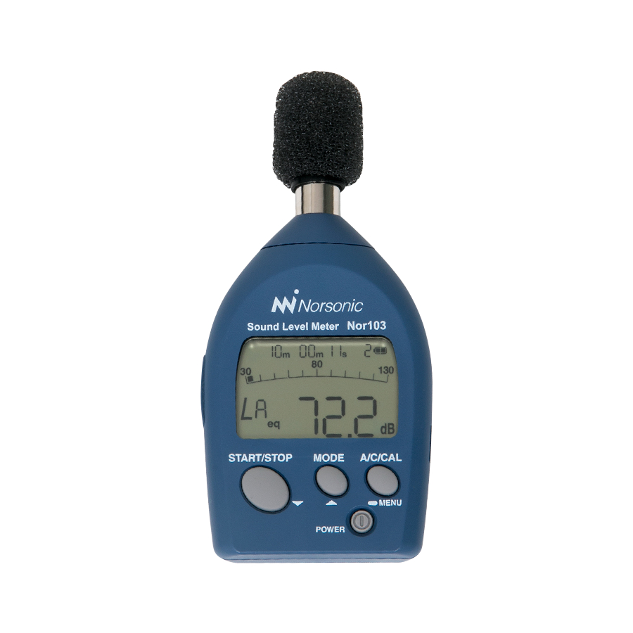
Nor103 is a small and versatile IEC Class 1 sound level meter. The
combination of a big graphical display and only three function buttons
makes this sound level meter easy to operate, even by non-acousticians.
It displays the current sound pressure level and calculates both sound exposure
level and the equivalent continuous sound level. After the measurement you it
gives you also the Fmax or Cpeak reported and stored. These are basic acoustic
figures that are widely used for general noise measurements and reporting.
nor103
SOUND LEVEL METER
INSTRUCTION
MANUAL
Advertisement

Related Manuals for Norsonic nor103


Summary of Contents for Norsonic nor103
- Page 1 INSTRUCTION MANUAL Nor103 is a small and versatile IEC Class 1 sound level meter. The combination of a big graphical display and only three function buttons makes this sound level meter easy to operate, even by non-acousticians. It displays the current sound pressure level and calculates both sound exposure level and the equivalent continuous sound level.
- Page 2 Every effort has been made to supply complete and accurate information. However, Norsonic AS assumes no responsibility for the use of – nor for the consequential damages of the use of – this informa- tion and/or the instrumentation described herein. Furthermore...
- Page 3 Depending on your requirements and your familiarity with sound measurements as such, you may find that you use some parts of this manual often and others not at all. The very first chapter acquaints you with the Nor103 and describes its features and possibilities.
- Page 4 Overview Precautions • Operate the unit only as described in this manual. • Do not drop the unit. Protect it from shocks and vibration. • The permissible environmental temperature range for operation of the unit is -10 to +50°C. Relative humidity must be between 10% and 90%. •...
- Page 5 Safety In this manual, important safety instructions are specially marked as shown below. To prevent the risk of death or injury to persons and severe damage to the unit or pe- ripheral equipment, make sure that all instructions are fully understood and observed. Important! Disregarding instructions printed here incurs the risk of damage to the product.
-
Page 7: Table Of Contents
Contents Chapter 1 Introducing the sound level meter Nor103 ......1 Chapter 2 Taking a closer look at the instrument ........3 Chapter 3 Calibrating the instrument ............9 Chapter 5 Making a measurement ............11 Chapter 6 Memory handling ..............15 Chapter 7 Batteries ................17... -
Page 9: Introducing The Sound Level Meter Nor103
Introducing the sound level meter Nor103 The sound level meter Nor103 is a class 1 sound level meter and complies with IEC61672-1 and is able to measure a number of acoustic parameters. The microphone is a 1/2-inch electret condenser microphone. It has a wide 107 dB linearity range, measuring sound levels between 30 and 137 dB, with no need to select the range. - Page 10 During the measurement you have instant access to all measurement values. With the Nor103 you are able to do all basic noise measurements – community noise, industrial hygiene, product control and more.
-
Page 11: Taking A Closer Look At The Instrument
Instruction Manual Taking a closer look at the instrument The Nor103 is delivered assembled and ready. We recommend that the microphone is always mounted on the preamplifier as this will prevent dust and dirt to enter the insulator around the sensitive signal terminal on the microphone. - Page 12 Chapter 2 Taking a closer look at Nor103 Sleep mode If powered and left unattended and unoperated with the measurement screen being shown and no key is pressed for 10 minutes, the unit enters sleep mode and the sleep mode screen appears. Power consumption is 30% of normal in sleep mode.
- Page 13 Norsonic Nor103 Instruction Manual Important! Do not unscrew the microphone from the preamlifier. MODE Changes the processing result display in the measurement screen and processing screen. Also used to change setting values in the calibration screen, menu screen, and recall screen.
- Page 14 Chapter 2 Taking a closer look at Nor103 AC out connector An AC signal weighted with frequency weighting characteristic Z is output here (con- stant output when an AC out cable is connected). Connect the unit with the optional AC out cable to external equipment.
- Page 15 Norsonic Nor103 Instruction Manual Attachments Windscreen We recommend using the windscreen to reduce wind noise and to protect the micro- phone from dust. Windscreen fall out prevention rubber prevents the windscreen from dropping off the microphone. Turn the fall out...
- Page 16 Chapter 2 Taking a closer look at Nor103 Hand strap To help prevent dropping of the unit, pass your wrist through this strap when holding the unit for measuring. Attach the hand strap as shown below. POWER Strap mount Hand strap...
-
Page 17: Calibrating The Instrument
Carrying out the calibration According to IEC 61672-1, a class 1 sound calibrator shall be used, such as the Norsonic sound calibrator Nor1255 or Nor1256. (Class 1 sound calibrator as defined by the International standard for sound calibrators: IEC 60942.) Do as follows: Access calibration mode. - Page 18 NOTE! Be aware of the fact that instruments using free-field Microphones, like Nor103, shall sometimes be adjusted to a value slightly lower than the output level of the sound calibrator.
-
Page 19: Chapter 5 Making A Measurement
Norsonic Nor103 Instruction Manual Making a measurement Measurement and processing screen Elapsed time Measurement time Address number Battery indication Processing mark Bar graph, level range scale Sound level Sound level under range overload indication indication Processing result Processing under range... - Page 20 Chapter 4 Making a measurement Bar graph, level range scale Shows the sound level in a bar graph. Sound level overload indication Shows that the sound level has exceeded the measurement range. Processing result overload indication Appears during processing when the sound level exceeds the measurement range, and remains until the next process starts.
- Page 21 Norsonic Nor103 Instruction Manual Measurement settings In the measurement screen, press and hold for 2 seconds the A/C/CAL key to switch to the menu screen/settings (not available during processing). Range setting Press the START/STOP key or the MODE key to select the following range settings.
- Page 22 Chapter 4 Making a measurement Setting measurement time Press the A/C/CAL key to proceed in the settings menu Press the START/STOP key or the MODE key to select the following settings. 1 m (1 minute), 5 m (5 minutes), 10 m (10 minutes), 1 h (1 hour). Flashes every 0.5 Starting the Measurement...
-
Page 23: Chapter 6 Memory Handling
Norsonic Nor103 Instruction Manual Memory handling Recalling stored data Press the A/C/CAL key until the recall screen appears. The most recent processing result is shown. The display will look similar as shown on the figure, with Recall written in the upper right corner. - Page 24 Chapter 5 Memory handling Clearing stored data Press the A/C/CAL key for 3 or more seconds while the recall screen is shown and a screen asking you to confirm clearing of the data appears. ALL and CLr flash alternately on the screen every 0.5 seconds.
-
Page 25: Chapter 7 Batteries
Norsonic Nor103 Instruction Manual Batteries Inserting or changing batteries Important! Make sure the unit is turn off before removing old batteries. Remove the battery compartment cover on the rear of the unit. Press and pull in the arrow direction. Take out eventual old batteries an insert two new, size AAA (IEC R03, LR03) batteries into the battery compartment. - Page 26 Chapter 6 Batteries Battery life (at 23°C, using wide range) Manganese batteries: approx. 3 hours Alkaline batteries: approx. 9 hours Battery life will be reduced by 20% when a DC output cable is connected. Full charge Indicator flashing (replace the batteries) Battery indication Indicates battery charge.
-
Page 27: Chapter 8 Technical Specifications
Norsonic Nor103 Instruction Manual Technical specifications Applicable legislation IEC 61672-1 class 1 JIS C 1509-1 class 1 JIS C 1516 class 1 CE marking WEEE Directive Measurement functions Processing type Sound level L Equivalent continuous sound level L Sound exposure level L... - Page 28 Chapter 7 Technical specifications Inherent noise level Wide range: A weighting: 21 dB or less C weighting: 29 dB or less Peak range: A weighting: 54 dB or less C weighting: 54 dB or less Measurement frequency range 10 Hz to 20 kHz Reference frequency 1 kHz Reference sound pressure level...
- Page 29 Norsonic Nor103 Instruction Manual Windscreen Conforms to IEC 61672-1 Class 1 even when the windscreen is attached Display TN positive display, reflective type Numeric display 0.1 dB resolution Bar graph Scale range 100 dB Resolution 5 dB Display update cycle 0.1 s Warning indications Over (overload): appears at 137.4 dB (at 1 kHz)
- Page 30 Chapter 7 Technical specifications PC cable Use an optional adapter cable to send stored data to a computer. Power requirements 2 size AAA (IEC R03, LR03) batteries Power consumption: Approx. 80 mA (when operating at 3 V) (Approx. 30% in sleep mode) Battery life (at normal temperature): Wide range Approx.
- Page 31 Norsonic Nor103 Instruction Manual Dimensional drawings 63 mm 23,5 mm Front view Right side View Left side view Rear view...
- Page 32 Remark paragraph Performance specifications General 5.1.4 Configuration & normal mode of 9.2.1 b) Configuration operation • Nor103 • Nor4617 • Windscreen fall out prevention rubber • Silicone cover (Attachments) Normal mode of operation Power on and off Unit powered 5.1.6 Models of microphone 9.2.1 c)
- Page 33 Norsonic Nor103 Instruction Manual 5.1.18 Initial time interval after switching 9.2.5 e) Less than 30 seconds. on power Adjustment to indicated levels 5.2.1 Model of sound calibrator(s) 9.2.4 a) Nor1251, Nor1255 or Nor1256 5.2.3 Procedure for calibration & 9.2.4 c)
- Page 34 Chapter 7 Technical specifications Time weighting F and S 5.7.1 Description of time weightings that 9.2.2 d) F, S are provided 5.10- 5.11 Overload and Under-range indication 5.10.1 Operation & interpretation of 9.2.5 k) Measurement screen and overload indicators processing screen 5.11.1 Operation &...
- Page 35 Norsonic Nor103 Instruction Manual Electric output connector (DC Frequency weighting: A, C output) Output voltage: 3.0 V (at 130 dB), 25 mV/dB Output range: 0.5 to 3.2 V Output impedance: 50 Ω Load impedance: >10 kΩ 5.17 Timing facilities 5.17.1 Procedure to preset the integra- 9.2.5 g)
- Page 36 Effect of optional accessories 9.2.6 a) Fig. 4 Influence of Nor4617 (windscreen) on acoustic performance of Nor103 Statement of conformance with Compliant with IEC 61672-1, optional accessories (windscreen) with Windscreen Nor4617 mounted Operation of 1/1 - 1/3 octave band 9.2.6 c)
- Page 37 Norsonic Nor103 Instruction Manual 9.2.2 a) Description of quantities which 5.15.4 time-weighted sound level, can be measured equivalent continuous sound level, maximum value of time-weighted sound level, sound exposure level, peak sound level 9.2.2 b) Relative free-fi eld response Directional Characteristics with as function of incidence angle Horizontal Direction (Fig.
- Page 38 Chapter 7 Technical specifications 9.2.4 d) Data for correction - with and 5.2.4 - Refer to 5.2.4 - 5.2.5 without windscreen - for : 5.2.5 Deviation of average frequency response to uniform frequency response. Case reflection and microphone diffraction Including values for expanded uncertainties.
- Page 39 Norsonic Nor103 Instruction Manual 9.2.5 n) Length & type of interface cable 5.18.1 Refer to 5.18.1 and characteristics of connected devices 9.2.5 o) Self-noise at the more sensitive 5.6.1 Refer to 5.6.1 ranges (including microphone). Averaging time ≥ 30 s.
- Page 40 Chapter 7 Technical specifications 9.3 f) Starting point for the level linearity 5.5.10 Refer to 5.5.10 error For frequencies 31.5 Hz, 1, 4, 8 and 12.5 kHz At the reference level range 9.3 g) Dummy microphone: Design 5.1.15 Refer to 5.1.15 goal and tolerance 9.3 h) Self-noise at the more sensitive...
- Page 41 Norsonic Nor103 Instruction Manual Nor103 - IEC61672-1 Frequency Response UC-59 Frequency Total Nominal Exact Electrical Total Windscree Frequency Response Expanded frequency frequency response Response Correction Response (dB) case Uncertanty (dB) (dB) (dB) (dB) reflection (dB) 63,1 -0,1 79,4 100,0 -0,1...
- Page 42 Chapter 7 Technical specifications Reference incidence direction and reference point position Reference point position Center of diaphragm plane Reference direction of incidence Reference point position Center of diaphragm plane Fig. 1 Reference incidence direction and reference point position...
- Page 43 Norsonic Nor103 Instruction Manual Frequency Response The frequency response of a sound field microphone is expressed as the frequency response in the reference direction of incidence (0º). The diagram below shows an example for the frequency response of the microphone UC-59.
- Page 44 With Nor4617 Wind velocity (m/s) Fig. 3 Wind noise reduction effect -0.5 -1.0 -1.5 -2.0 -2.5 -3.0 1 000 10 000 100 000 Frequency (Hz) Fig. 4 Influence of windscreen Nor4617 on acoustic performance of Nor103 (Referenced to Nor103 characteristics)
- Page 45 Norsonic Nor103 Instruction Manual The greatest susceptibility configuration for radio frequency fields Ferrite cores Computer START/STOP MODE A/C/CAL MENU Nor4596 POWER Nor103 Polarization direction is parallel to drawing plane Antenna Operation mode: normal operation Connection pattern - PC adapter cable (with ferrite cores) Nor4596 2.5 m Fig.
- Page 46 Chapter 7 Technical specifications The lower and upper limits of the linear operating range Tab. 2 The lower and upper limits of the linear operating range A-weighting Sound level (dB) Frequency (Hz) 31.5 12.5 K Upper 97.0 137.0 136.0 133.0 130.0 Start 94.0...
- Page 47 The directional characteristics of Nor103 is a measure of its differing sensitivity sound waves arriving from various angles. Since the electret condenser microphone used in the Nor103 is a pressure-sensitive type, it should be equally sensitive in all directions. However, refraction and cavity effects cause a certain microphone direc- tional response at high frequencies.
- Page 48 Chapter 7 Technical specifications Directional Characteristics with Directional Characteristics with Horizontal Direction Vertical Direction Frequency [Hz] Frequency [Hz] Angle Angle 501 1000 1995 3981 7499 15849 501 1000 1995 3981 7499 15849 0º 0º 10º -0,03 0,03 0,03 -0,01 0,02 -0,22 10º...
- Page 49 Norsonic Nor103 Instruction Manual Random incidence response...
- Page 51 Declaration of Conformity We, Norsonic AS, Gunnersbråtan 2, N-3409 Tranby, Norway, declare under our sole responsibility that the product: Sound Level Meter Nor103 to which this declaration relates, is in conformity with the following standards or other normative documents: Performance complying with: IEC 61672-1:2013 class 1 This Declaration of Conformity does not affect our warranty obligations.
- Page 52 Norsonic AS supplies a complete range of instrumentation for acoustics – from sound calibrators, microphones and P.O. Box 24 preamplifiers; via small handheld sound level meters to N-3421 Lierskogen advanced, yet portable, real time analysers, but also spec- Norway Tel: +47 3285 8900...
Need help?
Do you have a question about the nor103 and is the answer not in the manual?
Questions and answers