Sign In
Upload
Manuals
Brands
Norsonic Manuals
Measuring Instruments
NOR150
Norsonic NOR150 Manuals
Manuals and User Guides for Norsonic NOR150. We have
3
Norsonic NOR150 manuals available for free PDF download: Instruction Manual, Manual
Norsonic NOR150 Instruction Manual (216 pages)
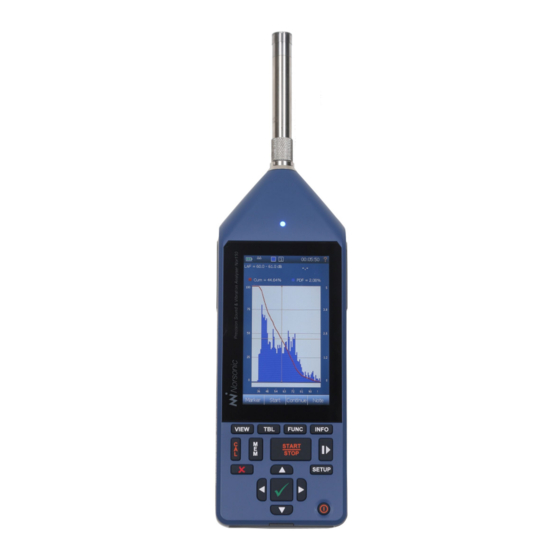
SOUND & VIBRATION ANALYSER
Brand:
Norsonic
| Category:
Measuring Instruments
| Size: 21 MB
Table of Contents
Table of Contents
5
Chapter 1 Important Information
17
Safety Instructions
17
Precautions
18
Chapter 2 Taking a Closer Look at the Instrument
19
Switching ON/OFF
20
Keyboard
20
Touch Sensitive Screen
21
The Main Status LED
23
Input and Output Connectors
24
On the Use of the Internal Battery Vs. External DC
25
Charging the Internal Battery
25
If Power Fails
26
Power Saving - Maximize Your Battery Power
26
Optional Extensions
27
Software Maintenance
27
Chapter 3 Your First Measurement
28
Turn on the Nor150
28
Select the Transducer
28
Check the Calibration
28
Select a Standard Set up
28
Start and Stop of the Measurement
28
Saving the Measurement to the Memory
29
Reducing the Influence of the Operator
29
Removing the Influence of the Instrument Itself
29
Limiting the Influence of Wind and Dust
29
Chapter 4 The Measurement Functions Available
30
Chapter 5 Setting up the Analyser
35
The Organisation of the Display
35
The Status Bar
36
Symbol # 1 Battery Gauge / External Power
36
Symbol # 2; Overload Indication
37
Symbol # 3, Measurement Status
37
Symbol # 4, Application Mode
37
The Soft Key Bar
37
The Measurement Picture
38
On-Screen Menus
39
Activate and Deactivate the Result Displays
40
Cursor Handling
41
The Main Menu System - an Overview
41
On/Off/Available/Disabled Indication
42
Chapter 6 Selecting the Different Views and the Parameters to Display
43
Function Selection - Selecting the Measurement Parameters
46
SPL Live in Ended Mode
49
Numerical Tables
49
Chapter 7 Input Selection Menu
50
The Sound Channel 1 or 2 Menu
51
Line and Vibration Sensor
51
Microphones
51
Outdoor Microphones
52
The Transducer Menu
52
Adding a New Sensor
54
Preamplifier Selection
55
Using Other Transducers
55
Chapter 8 Calibrating the Instrument - Field Check
56
When to Calibrate
56
Carrying out the Field Check / Calibration
56
Calibrating a Vibration Sensor
58
Microphone Check
58
Chapter 9 Measurement Setup Menu
60
High-Pass Input Filter
61
Weather Station
63
Chapter 10 FFT
64
Introduction
64
How to Select FFT
64
Making a Measurement
64
Calibration
65
Corrections
65
Chapter 11 Trigger Selection Menu
66
Global Trigger
66
The Event Trigger
69
Chapter 12 Working with Markers
72
Setting up Markers - the Marker Setup Menu
72
System Specified Markers
73
Adding a Marker to an Ongoing Measurement
74
Working with Markers - Post Processing
74
Chapter 13 Recording the Sound - Audio Record and Replay
75
Making a Recording
76
Listening - Replaying an Audio Recording
77
Insert a Reference Tone as a Recording
77
Chapter 14 Camera
78
Internal Camera
78
Device Camera
78
IP Camera
79
Chapter 15 Voice and Text Notes
80
Adding Text and Voice Notes
80
Retrieving Text and Voice Notes
80
Chapter 16 Pausing and Resuming a Measurement
82
The Difference between a "Pause" and a "Hold" Function
83
Chapter 17 Storing a Measurement - Memory Organising Menu
84
File Name
85
Unique Measurement Identifier
86
Save and Manage Measurement Setup
86
Write Protected Setup
86
Rename, Delete, Move
87
Set Factory Default
87
Save Debug Log
87
Chapter 18 Application Selection Menu - Predefined Setups
88
Creating a User Defined Setup
89
Chapter 19 Signal Generator (Optional)
90
Chapter 20 Building Acoustic
91
Introduction
91
Measurement Mode
92
Colour Assignment
92
Display Views in Measurement Mode
93
Single-Channel Views
94
Dual-Channel Views
94
On-Screen Menus
94
Setup
95
Input - Setup
95
Type - Setup
95
Level - Setup (Figure 20.16)
96
Reverberation - Setup (Figure 20.18)
96
Rating - Setup
97
Standard
97
Source (Figure 20.21)
98
Receiving (Figure 20.22)
98
Test Specimen
99
Various Parameters (Figure 20.25)
99
Signal Generator - Setup (Figure 20.26)
99
Memory - Setup (Figure 20.27)
100
Making the Level Measurements
100
Making the Background Noise Measurements
102
Making the Reverberation Time Measurements
103
Project Mode
104
Display Views in Project Mode
104
Rating Views 1 - 4
106
Rating View-1
106
Rating View-2
107
Rating View-3
107
Rating View-4
107
Measurements Views 1 - 4
108
View 1- 4 for Reverberation Time Measurements
109
View 1 - 4 for Receiving Room Measurements
109
Measurement View-1
110
Measurement View-2
111
Measurement View-3
112
Measurement View-4
113
Exclude Measurement Positions
114
Adjust Reverberation Decay Line
114
Start a New Project
115
Continue an Existing Project
115
Chapter 21 Sound Intensity
116
Setting up the Instrument for Intensity
117
Assembling and Handling the Probe
117
Probe Dismantling
119
Transducer Setup
119
Connecting a Smartphone
121
Calibration and Phase Correction
121
Pressure Calibration
121
Phase Correction
122
Verification Procedure
125
Configuring an Intensity Measurement
126
Probe and Environment Parameters
127
Defining a Measurement Surface
127
Measurement Settings
131
Navigating the Sound Intensity Mode
134
Introducing the Surface Scopes
134
The Views
135
Errors and Warnings
137
Saving and Loading Intensity Projects
139
Helpful Features
139
Using the Smartphone
139
Sound Power Using ISO 9614-2
139
Measurement Configuration
140
Measuring
141
Reviewing the Measurements
142
Segment Scope
142
Surface Scope
143
Total Scope
144
Measurement Functions and Indicators
145
Warning Indicators
145
Sound Power Using ISO 9614-1
146
Measurement Configuration
146
Measurement Time
147
Filtering
147
Measurement Precision
147
Temporal Variability
148
Surface Definition
148
Measuring
149
Temporal Variability
149
Main Measurement
151
Reviewing the Measurements
151
Total Scope
154
Measurement Functions and Indicators
157
Chapter 22 Instrument Specific Setup
159
Digital and Analog I/O
159
Digital Output
160
Headset
160
Analog Output
160
Communication
161
Security
162
Connection
166
Keyboard
166
Reference Tone
166
Power Settings
166
Instrument Name
167
Date and Time
167
Language
168
Number Format
169
About
169
Install New Software, Service Pack or New Fonts
169
The Software License System
170
Installing New Options
170
Activate Evaluation License
170
Chapter 23 Norsonic Software
171
Chapter 24 Technical Specifications
172
Firmware Version
172
Type of Instrument
172
Analog Inputs
173
Input Connector
173
Microphone Input Socket (Outside View)
173
High-Pass Input Filter
174
Nor1225 Data
174
Preamplifier
174
Nor1209 Data
175
Nor1209 Technical Specifications
175
Acoustical Data
176
Acoustical Data for Nor1225 and Nor1209 Mounted on Nor150
176
Reference Direction
176
Microphone Reference Point
176
Detailed Table for Level Corrections According to IEC 62585
177
Directional Response - Horizontal
181
Directional Response - Vertical
183
Directional Response - Horizontal with Wind Screen
185
Directional Response - Vertical with Wind Screen
187
Verification of the Free Field Response
189
Analog to Digital Converters
189
Frequency Weightings
189
Weighting Networks
189
Filters
189
Filter Type
189
Fft
189
Level Detector
190
Detector Type
190
Crest Factor Capability
190
Overload Indication
190
Under-Range Indication
190
Time Weightings and Measured Functions
190
Level Distribution
191
Statistics
191
Indication on the Screen of the Nor150
192
Indication Range
192
Self-Noise Levels
192
Electric Self-Noise
192
Acoustic Self-Noise
193
Considerations for Low Noise Measurements
193
Measurement Duration and Resolution
193
Measurement Ranges
194
Total Range for Measurement of A-Weighted Levels
194
Total Range for Measurement of C-Weighted Levels
194
Total Range for Measurement of Z-Weighted Levels
194
Measurement Range for C-Weighted Peak Levels
195
The Nor150 Used for Electrical Measurements
195
Electrical Verification Measurements
195
Power Supply
195
Internal Battery
195
Power Consumption
196
External DC / Charging Input
196
Mains Adapter Nor345A
196
Display
196
Keyboard
196
Adjustment of Indicated Levels
197
Random Response
197
Windscreen
197
High Levels
197
Diffraction Around the Instrument Casing
198
The General I/O Socket
198
Signal Output - Noise Generator
199
Signal Output - Microphone Signal
199
Serial I/O Port
199
Digital Inputs
199
Digital Output Control Lines
199
Headset Input and Output Socket
200
LAN Interface
200
USB Interface
200
Data / Result Storage
200
SD-Card
200
Internal Memory
200
Environmental Conditions
201
Warm-Up Time
201
Changes in the Environmental Conditions
201
Sensitivity to Static Pressure
201
Sensitivity for Vibration
202
Sensitivity for Magnetic Fields
202
Sensitivity for Radio Frequencies
202
Emission of Radio Frequencies
202
Sensitivity for AC Power Frequency
203
Recovery after Electrostatic Discharge
203
Size and Weight
203
Appendix A Index
207
Appendix B Battery Certification N38.3 Transport of Dangerous Goods
213
Appendix C Declaration of Conformity
215
Advertisement
Norsonic NOR150 Instruction Manual (198 pages)
SOUND & VIBRATION
Brand:
Norsonic
| Category:
Measuring Instruments
| Size: 6 MB
Table of Contents
Table of Contents
5
Chapter 1 Important Information
15
Safety Instructions
15
Precautions
16
Storage
16
Taking a Closer Look at the Instrument
17
Switching ON/OFF
18
Keyboard
18
Touch Sensitive Screen
19
The Main Status LED
21
Input and Output Connectors
22
On the Use of the Internal Battery Vs. External DC
23
Charging the Internal Battery
23
If Power Fails
24
Optional Extensions
24
Software Maintenance
24
Chapter 3 Your First Measurement
25
Turn on the Nor150
25
Select the Transducer
25
Check the Calibration
25
Select a Standard Set up
25
Start and Stop of the Measurement
25
Saving the Measurement to the Memory
26
Reducing the Influence of the Operator
26
Removing the Influence of the Instrument Itself
26
Limiting the Influence of Wind and Dust
26
The Measurement Functions Available
27
Chapter 5 Setting up the Analyser
32
The Organisation of the Display
32
The Status Bar
33
Symbol # 1 Battery Gauge / External Power
33
Symbol # 2; Overload Indication
34
Symbol # 3, Measurement Status
34
Symbol # 4, Application Mode
34
The Soft Key Bar
34
The Measurement Picture
35
On-Screen Menus
36
Activate and Deactivate the Result Displays
37
Cursor Handling
38
The Main Menu System - an Overview
38
On/Off/Available/Disabled Indication
39
Selecting the Different Views and the Parameters to Display
40
Function Selection - Selecting the Measurement Parameters
42
SPL Live in Ended Mode
45
Numerical Tables
45
Input Selection Menu
46
The Sound Channel 1 or 2 Menu
47
The Transducer Menu
48
Adding a New Sensor
50
Preamplifier Selection
51
Using Other Transducers
51
Calibrating the Instrument - Field Check
52
When to Calibrate
52
Carrying out the Field Check / Calibration
52
Microphone Check
54
Measurement Setup Menu
56
Trigger Selection Menu
59
Global Trigger
59
The Event Trigger
62
Chapter 11 Working with Markers
65
Setting up Markers - the Marker Setup Menu
65
System Specified Markers
66
Adding a Marker to an Ongoing Measurement
67
Working with Markers - Post Processing
67
Chapter 12 Recording the Sound - Audio Record and Replay
68
Making a Recording
69
Listening - Replaying an Audio Recording
70
Insert a Reference Tone as a Recording
70
Chapter 13 Camera
71
Internal Camera
71
Device Camera
71
IP Camera
72
Chapter 14 Voice and Text Notes
73
Adding Text and Voice Notes
73
Retrieving Text and Voice Notes
73
Pausing and Resuming a Measurement
75
The Difference between a "Pause" and a "Hold" Function
76
Storing a Measurement - Memory Organising Menu
77
File Name
78
Rename, Delete, Move
78
Application Selection Menu - Predefined Setups
79
Storing a Setup
80
Chapter 18 Building Acoustic
81
Introduction
81
SPL Mode
82
Display in SPL Mode
82
Single-Channel Views
82
Dual-Channel Views
83
On-Screen Menus
84
Setup
84
Input - Setup
85
Type - Setup
85
Level - Setup (Figure 18.17)
86
Reverberation - Setup (Figure 18.19)
86
Rating - Setup
87
Standard
87
Source (Figure 18.21)
88
Receiving (Figure 18.22)
88
Test Specimen
89
Various Parameters (Figure 18.25)
89
Signal Generator - Setup (Figure 18.25)
89
Memory - Setup (Figure 18.26)
90
Making the Level Measurements
90
Making the Background Noise Measurements
92
Making the Reverberation Time Measurements
93
Data Mode
94
Display in Data Mode
94
Rating Views 1 - 4
95
Rating View-1
95
Rating View-2
96
Rating View-3
96
Rating View-4
96
Measurements Views 1 - 4
97
View 1- 4 for Reverberation Time Measurements
98
View 1 - 4 for Receiving Room Measurements
98
Measurement View-1
99
Measurement View-2
100
Measurement View-3
101
Measurement View-4
102
Start a New Project
103
Chapter 19 Sound Intensity
104
Setting up the Instrument for Intensity
105
Assembling and Handling the Probe
105
Probe Dismantling
107
Transducer Setup
107
Connecting a Smartphone
109
Calibration and Phase Correction
111
Pressure Calibration
111
Phase Correction
112
Verification Procedure
114
Configuring an Intensity Measurement
115
Probe and Environment Parameters
116
Defining a Measurement Surface
116
Measurement Settings
119
Navigating the Sound Intensity Mode
121
Introducing the Surface Scopes
122
The Views
122
Errors and Warnings
125
Saving and Loading Intensity Projects
126
Helpful Features
126
Using the Smartphone
126
Sound Power Using ISO 9614-2
128
Measurement Configuration
128
Measuring
129
Reviewing the Measurements
130
Measurement Functions and Indicators
133
Chapter 20 Instrument SpecifiC Setup
134
The Software License System
136
Installing New Options
136
Activate Evaluation License
136
Signal Generator (Optional)
137
Chapter 21 Norsonic Software
138
Norconnect Nor1051
138
Installation
138
Description
139
Quick Reference Guide
141
Connecting the Instrument
141
Transfer
141
Where Are My Measurements and Reports Stored
141
Making Reports
143
Building Acoustic- and Sound Intensity Measurements Reports
145
Details
147
File Browser
147
SD Card Connection
148
Graph View
149
Choose/Add Function
150
Concatenate Measurements
151
Sort Criteria
152
Excel Reports
154
Enhanced Reports with Nor850 and Norreview
155
Where Are My Measurements Stored
156
Search
157
Initialize Nor150 USB
158
Language Selection
158
Info
159
Chapter 22 Technical Specifications
160
Firmware Version
160
Type of Instrument
160
Analog Inputs
161
Input Connector
161
Microphone Input Socket (Outside View)
161
High-Pass Input Filter
162
Nor1225 Data
162
Preamplifier
162
Nor1209 Data
163
Nor1209 Technical Specifications
164
Acoustical Data
165
Acoustical Data for Nor1225 and Nor1209 Mounted on Nor150
165
Reference Direction
165
Microphone Reference Point
165
Directional Response - Horizontal
169
Directional Response - Vertical
171
Directional Response - Horizontal with Wind Screen
173
Directional Response - Vertical with Wind Screen
175
Verification of the Free Field Response
177
Analog to Digital Converters
177
Frequency Weightings
177
Weighting Networks
177
Filters
177
Filter Type
177
Level Detector
177
Detector Type
178
Crest Factor Capability
178
Overload Indication
178
Under-Range Indication
178
Time Weightings and Measured Functions
178
Level Distribution
179
Statistics
179
Indication on the Screen of the Nor150
179
Indication Range
180
Self-Noise Levels
180
Electric Self-Noise
180
Acoustic Self-Noise
181
Considerations for Low Noise Measurements
181
Measurement Duration and Resolution
181
Measurement Ranges
182
Total Range for Measurement of A-Weighted Levels
182
Total Range for Measurement of C-Weighted Levels
182
Total Range for Measurement of Z-Weighted Levels
182
Measurement Range for C-Weighted Peak Levels
183
The Nor150 Used for Electrical Measurements
183
Electrical Verification Measurements
183
Power Supply
183
Internal Battery
183
Power Consumption
184
External DC / Charging Input
184
Mains Adapter Nor345A
184
Display
184
Keyboard
184
Adjustment of Indicated Levels
185
Random Response
185
Windscreen
185
High Levels
185
Diffraction Around the Instrument Casing
186
The General I/O Socket
186
Signal Output - Noise Generator
187
Signal Output - Microphone Signal
187
Serial I/O Port
187
Digital Inputs
187
Digital Output Control Lines
187
Headset Input and Output Socket
188
LAN Interface
188
USB Interface
188
Data / Result Storage
188
SD-Card
188
Internal Memory
188
Environmental Conditions
189
Warm-Up Time
189
Changes in the Environmental Conditions
189
Sensitivity to Static Pressure
189
Sensitivity for Vibration
189
Sensitivity for Magnetic Fields
190
Sensitivity for Radio Frequencies
190
Emission of Radio Frequencies
190
Sensitivity for AC Power Frequency
190
Recovery after Electrostatic Discharge
191
Size and Weight
191
Declaration of Conformity
197
Norsonic NOR150 Manual (23 pages)
Brand:
Norsonic
| Category:
Test Equipment
| Size: 1 MB
Table of Contents
Reference Tone
2
Pink Noise
3
Measurement
19
Playback in Norreview
20
Output Level
21
Playback
22
Advertisement
Advertisement
Related Products
Norsonic nor121
Norsonic nor118
Norsonic nor140
Norsonic nor103
Norsonic nor145
Norsonic Nor1212
Norsonic nor1217
Norsonic nor1251
Norsonic nor1218
Norsonic nor1256
Norsonic Categories
Measuring Instruments
Microphone
Test Equipment
Stereo System
Speakers
More Norsonic Manuals
Login
Sign In
OR
Sign in with Facebook
Sign in with Google
Upload manual
Upload from disk
Upload from URL