Table of Contents
Advertisement
Quick Links
INSTRUCTION
MANUAL
INSTRUMENT SOFTWARE VERSION
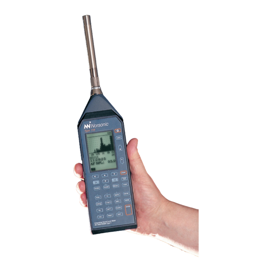
A sound level meter with built-in real
time analyser capabilities. Parallel
octave filters are standard (optional
in some markets), but the impressive
list of optional extensions include
sound
power
calculations,
octave filters and statistics in every
frequency band, multispectrum and
reverberation
time
measurements.
The instrument logs level vs. time
(optional) and when it is equipped
with multiple time constants and
the enhanced profile extension, a
multitude of functions is logged si-
multaneously. The 120 dB dynamic
range eliminates the need for range
setting. A large memory and high-
speed data transfer rates complete
our user-friendliest solution to date.
nor
118
REAL TIME ANALYSER
1.2
third
Advertisement
Table of Contents

Related Manuals for Norsonic nor118


Summary of Contents for Norsonic nor118
- Page 1 INSTRUCTION MANUAL INSTRUMENT SOFTWARE VERSION A sound level meter with built-in real time analyser capabilities. Parallel octave filters are standard (optional in some markets), but the impressive list of optional extensions include sound power calculations, third octave filters and statistics in every frequency band, multispectrum and reverberation time...
- Page 3 REAL TIME ANALYSER...
- Page 4 Norsonic AS reserves the right to amend any of the infor- mation given in this manual in order to take account of new developments.
- Page 5 e first measurement description outlines the use of the Nor118 as a simple sound level Our objective with this manual has been to address meter. e second description extends the description to your goals and needs.
-
Page 6: Table Of Contents
Contents Contents Chapter 1 Introducing the Nor118 Introducing the sound level meter Nor118 ............2 No external modules..................2 The functions available..................3 The main features – an overview..............3 Real time frequency analysis................4 Time profile measurements ................5 Multispectral measurements................7 Source coding ....................7 Excellent for noise monitoring ..............8 The principle of optional extensions..............8... - Page 7 Norsonic Nor118 User Guide Chapter 4 Simple sound measurements Simple sound measurements................ 17 Setting the duration..................17 Statistics....................... 18 Instruments with time profile installed ............19 Setting the time constant................19 Instruments with multiple time constants........... 19 Multiple time constants and statistics ............19 C or Z as spectral weighting network ............
- Page 8 viii Contents No SPL after the measurement ..............30 Displaying the result tables................30 Statistics – displaying the percentiles ............30 Storing the acquired data................34 Printing out the results ................34 Chapter 6 Basic time profile measurements Basic time profile measurements ..............35 Global vs. profile..................35 Making measurements.................38 Presenting the L(t) as a table ...............
- Page 9 Norsonic Nor118 User Guide Making multispectrum measurements............47 e result tables ...................49 Chapter 10 Reverberation time measurements What is reverberation time? ................ 52 Excitation signals..................52 How we measure the reverberation time ............. 53 Backward integration................... 53 Least square fit..................... 53 Minimum reverberation times possible ............54...
- Page 10 Contents Approximate method...................66 Using reverberation time instead ..............67 Test room qualification requirements ............67 Chapter 13 Measuring the sound power Measuring the sound power ................68 Making measurements.................68 Background noise ..................68 Measurement Surface .................. 71 Sound Power Results ................... 71 Chapter 14 Memory handling Memory handling ..................72...
- Page 11 Norsonic Nor118 User Guide Setting the storage mode ................80 Other setup aspects..................80 Chapter 17 Transfer of data to a PC Transfer of data to a ................81 Chapter 18 Technical specifications Type of instrument ..................82 Analogue inputs...................82 Microphone input socket ................83 Highpass filter .....................83...
- Page 12 Contents General I/O socket ..................89 Analogue output ..................90 Serial I/O port .....................90 Digital inputs ....................90 Digital outputs.....................90 Microphone heating ..................90 Data storage ....................90 Environmental conditions ................91 Warm-up time ..................... 91 Sensitivity for vibration................91 Sensitivity for magnetic fields..............91 Size and weight....................
- Page 13 REAL TIME ANALYSER...
-
Page 14: Introducing The Nor118
As for all our sound measuring instruments, many of digital technology everywhere. the features in the Nor118 are optional and can be added We added a new display with higher resolution and upon order or as retrofit whenever required. In this way backlight, we added a larger memory, we added high- you don’t pay for features never used. -
Page 15: The Functions Available
Frequency analysis. can be expanded to include the ability to measure with all analysis extensions the Nor118 can do real time frequency three time constants (, , ) applied simultaneously. analysis in octaves (8 Hz to 16 kHz) or third-octaves (6.3... -
Page 16: Real Time Frequency Analysis
So, why not let the Nor118 take care of this for you? Just specify the measurement surface type (hemisphere or parallelepiped), its dimensions and the location of your e optional extension 4 adds statistical... -
Page 17: Time Profile Measurements
Adding option 4 to your Frequency band statistics. you with third-octave band measurements in the range Nor118 will expand your frequency analysis to even cal- 6.3 Hz to 20 kHz. culate the statistical level distribution for each frequency The two bandwidths share the type of functions band measured! In addition statistics will be calculated measured. - Page 18 Given the large memory of the Nor118 – the memory During the measurement you have instant access to the can hold approximately 2 500 000 values – the period dura- global analysis and profile.
-
Page 19: Multispectral Measurements
No problem! e time profile extension can be expanded time. into the enhanced profile extension – our option for the Nor118. Order it when you purchase your Nor118 or later, if that suits you better. In the enhanced mode, the instrument logs the time... -
Page 20: Excellent For Noise Monitoring
But, you don’t need to attend the measurement ses- Extensions are modules – made in hardware or made sions all the time. In fact, the Nor118 is able to do a lot as software, in the instrument or e.g. as software for your on its own. -
Page 21: Check Which Extensions Are Installed
Unless you are certain about the extensions installed in e below list The options available. your Nor118, we recommend that you spend a little time was complete and exhaustive by the time looking into the matter. of printing of this User Guide. However, constant improvements will normally result in new extensions becoming available on a regular basis. -
Page 22: Taking A Closer Look
the instrument the first time you use it. Be sure to take utmost care when e Nor118 comes with four batteries (1.5 V each). mounting the microphone cartridge onto the preampli- Battery lifetime is typically 8–12 hours (depends on fier. -
Page 23: Battery Voltage Vs. Time
Norsonic is voltage and use-time information (empty graph). not liable for consequential damages of the use of If powered from internal batteries and left unattended polarisation voltage and unoperated, the Nor118 will switch itself off after ten... -
Page 24: Setting The Time And Date
Chapter 2 Taking a closer look Screw only Microphone finger tight! cartridge Observe the Navigating in the menus. following general guidelines applicable to Default cartridge is designed for every Nor menu: Microphone 200V polarisa- preamplifier tion voltage, • To navigate between editable parameter fields in but this can be the menu, use the ... - Page 25 Norsonic Nor118 User Guide The front panel keys of the Nor118 Cursor keys to navigate in the men- us and to operate the graph cursors Causes the graph cursor to jump Power on/off one screenwidth in either direction Display backlight on/off...
-
Page 26: Calibrating The Instrument
However, measuring microphones are very delicate devices designed to fulfil very rigid specifications. is Since the Nor118 has a 120 dB dynamic range (10–130dB makes them vulnerable and subject to damage unless ), the 80 dB bar graph range is a display limitation only. - Page 27 Norsonic Nor118 User Guide Press the key to gain 1 Enter calibration mode. The sound calibrator should be mounted onto the micro- access to the Calibration menu. e display will typi- phone as shown here. Do not use the...
- Page 28 EXIT the sound level meter to indicate 113.8 dB (diffuse will be interpreted as the ± sign whenever the Nor118 correction off). expects numerical inputs (indicated by the # sign If other types of calibrators or electrostatic actua- appearing in the lower line of the display).
-
Page 29: Simple Sound Measurements
Norsonic Nor118 User Guide Simple sound measurements , the Nor may still be used as a simple sound level meter. e Observe the Navigating in the menus. only thing you really need to set up is the measurement... -
Page 30: Statistics
1% percentile. Going to measure very high levels? Likewise, for the 0.1% percentile the minimum As an optional extension the Nor118 is time required will be 100 seconds. Measurements able to measure very high sound pressure levels whose duration are shorter than these minimum without changing the microphone cartridge –... -
Page 31: Instruments With Time Profile Installed
PEAK To set the time constant press the key until the 16Hz to 16kHz (in the Nor118 it extends far beyond that required time constant appears in the display. To see this, – viz. 20–20 000 Hz +0 –1 dB) and is well-defined in an be sure to operate the ... -
Page 32: Making A Measurement
Chapter 4 Simple sound measurements Making a measurement To terminate an ongoing measurement: To start a measurement: • Press the key. e in the display indicates that • Press the key. a measurement is running. To resume a terminated measurement: To temporarily halt an ongoing measurement: •... -
Page 33: Resuming An Ended Measurement
Norsonic Nor118 User Guide Resuming an ended measurement e measurement time elapsed counter will be updated Assume that you have set up the instrument to measure to reflect the back-erase. Note that the statistics buffers for minutes and that you start the measurement. After ... -
Page 34: Displaying The Result Tables
Chapter 4 Simple sound measurements Displaying the result tables Units configured for the As an alternative to the above procedures, you may display German-speaking markets all the data in a single table. Press the key to produce If also equipped with and ... -
Page 35: Statistics - Displaying The Percentiles
Norsonic Nor118 User Guide Your user-editable percentile can be set to anything Displaying the result table using the other in the range 0.1–99.9 %, both extremes included. e spectral weighting function procedure is explained overleaf. Data measured, but not yet stored may be subject to changes in the user-defined percentile. -
Page 36: Displaying The Percentiles Table
e structure of the Nor118 is very simple, the folder sufficent number of samples. Using will not has the name of today’s date and the files are numbered work here. -
Page 37: Frequency Analysis
e frequency range is fixed and cannot be changed by the user. Bearing in mind that the dynamic range of the Nor118 is no less than 120 dB and that the instrument measures a fixed set of functions (which cannot be altered by you), there is not much left to set up before the instru- ment is ready to make a frequency analysis. -
Page 38: Statistics
Chapter 5 Frequency analysis Instrument without the multispectrum extension (option Cf. Basic time profile measurements, Enhanced time profile ) are not able to capture the spectrum as a function of measurements and Multispectrum measurements for details time. However, instruments equipped with the time pro- on logging the level vs. -
Page 39: Setting C Or Z As Spectral Weighting Network
e spectral weighting circuitry is flat within at least 16 Hz to 16 kHz (in the Nor118 it extends far beyond that) and it is well-defined in an upcoming standard (... -
Page 40: Switching To Displaying The Spectrum
Chapter 5 Frequency analysis Switching to displaying the spectrum To resume a paused measurement: Having activated the frequency mode and left the menu, • Press the / key again. Upon resuming the just press the f↔t key to display the level vs. frequency instrument will go on measuring until the total measure- and press again to return to the other display. -
Page 41: Resuming An Ended Measurement
Norsonic Nor118 User Guide To move the graph cursor about the frequency bands The back-erase feature • Use the ← & → keys. Use the |← & →| keys to move When you press the / key during an ongo- to the extreme left and extreme right. -
Page 42: No Spl After The Measurement
Chapter 5 Frequency analysis However, since the frequency analysis is made in paral- To return to mode, i.e. how the instrument lel with the traditional (- and - or -weighted) sound behaved before the measurement was started press the level measurement, the broadband peak levels and the ... - Page 43 Norsonic Nor118 User Guide Instruments configured for the German- speaking markets will measure (with time constant) and (with time constant) in addition – see below. The functions are available sequentially To display a certain function, press the key repeatedly until the function appears.
- Page 44 Chapter 5 Frequency analysis Displaying the result tables f ↔ t...
- Page 45 Norsonic Nor118 User Guide Your user-editable percentile can be set to anything in Editing the user-defined percentile the range 0.1–99.9 %, both extremes included. Data measured, but not yet stored may be subject to To enable the editing, the instrument must display changes in the user-defined percentile.
-
Page 46: Storing The Acquired Data
The S indicates Stored. both use folders and files. e structure of the Nor118 is very simple, the folder has the name of today’s date and the files are numbered consecutively from 0001 and upwards. is means, of... -
Page 47: Basic Time Profile Measurements
100 ms and upwards in 25 ms steps (but in 1 second steps lel with the traditional sound level measurement described above 1 second period length). in the chapter Simple sound measurements. If your Nor118 is The time profile is no less than an electronic level recorder! Global vs. profile e traditional sound level measurement and the fre-... - Page 48 Chapter 6 Basic time profile measurements The measurement duration setup menu The time profile display The ∆ indicates Display top scale profile (global is Total (global) duration indicated by a Σ) of measurement. Selected resolution Spectral weight- Graph cursor. No. of periods with ing function selected duration and applied to the...
- Page 49 Norsonic Nor118 User Guide Displaying the result tables Σ ↔ ∆...
-
Page 50: Making Measurements
for pause to denote that they were acquired in pause mode and that they do not All you need to do to set up the Nor118 to expand the participate in the global level assessments. -
Page 51: Presenting The L(T) As A Table
Norsonic Nor118 User Guide Presenting the L(t) as a table shorter than) the global measurement duration, the instrument will log the time profile in addition to the Numerical presentation of the acquired data works even global measurement. here. Press while in ∆ (profile) mode to produce the table. -
Page 52: Enhanced Time Profile Measurements
Chapter 7 Enhanced time profile measurements Enhanced time pro- file measurements – enhanced time profile Navigate in the menu as usual and use the and lets you select the functions to be measured as a func- ... -
Page 53: Copy The Setting To Prnt/Xfer
Norsonic Nor118 User Guide Units with multiple time constants installed may e same applies to the transfer of measured function include the time constant setting in the setup – see the values to your . You may not want to have all the data Fig. - Page 54 Chapter 7 Enhanced time profile measurements If you’ve set up a profile resolution different from (i.e. No back erase in profile pause mode. shorter than) the global measurement duration, the e resumption of a paused measurement instrument will log the time profile in addition to the will cause the ten seconds acquired immediately global measurement.
-
Page 55: Measuring In Enhanced Mode
Norsonic Nor118 User Guide Measuring in enhanced mode Presenting the L(t) as a table e enhanced time profile mode is similar to the basic Numerical presentation of the acquired data works even time mode and should thus be regarded as an add-on here. -
Page 56: Adding Markers To A Measurement
Chapter 8 Adding markers to a measurement Adding markers to a measurement a measurement where you later Enter source coding. With the enhanced profile option found out that you desperately need to know what (optional extension ) you may tag or code sources as they caused the level to be what it turned out to be? happen. -
Page 57: E Keys To Use
Norsonic Nor118 User Guide The keys to use e keys used to enter the markers are (marker 1), (marker 2), (marker 3) and (marker 4) since these keys are the lower most keys of the front panel and thus easy to reach during a measurement. -
Page 58: Multispectrum Measurements
Chapter 9 Multispectrum measurements Multispectrum measurements Setting up for multispectrum takes the instrument fur- ther along the axis of sophistication by introducing Multispectrum measurements can be made based on basic- multispectrum measurements. as well as enhanced time profile extensions installed. is upgrade of time profile permits complete spectra to be measured as a function of time –... -
Page 59: Making Multispectrum Measurements
Norsonic Nor118 User Guide To set up for multispectrum measurements (enhanced If you fail to activate functions for the filter bands, there time profile): will be no multispectrum data, either. Set up the duration and resolution To gain access to the profile function activation menu, press ... - Page 60 Chapter 9 Multispectrum measurements To move the cursor along the time profile axis: To see the spectrum of another moment in time: Make sure the display shows the time profile (level vs. Make sure the instrument is in profile mode and that time).
-
Page 61: E Result Tables
Norsonic Nor118 User Guide To see the level vs. time (the profile) graph of another leaf together with the displays and tables available for the frequency band: global part of the measurement. Make sure the display shows a time profile (level vs. - Page 62 Chapter 9 Multispectrum measurements...
- Page 63 Norsonic Nor118 User Guide Both tables are accessible during measurement, you can back-erasure also works as usual. For a discussion of these features, turn to Basic time profile measurements, Enhanced even start a measurement from within any of the tables!
-
Page 64: Reverberation Time Measurements
Chapter 10 Reverberation time measurements Reverberation time measurements for the Nor permits Once the steady state condition is reached, the level measurements of the reverberation time. If your wil increase no further. If you now switch off the sound instrument is equipped with filters, the reverberation source, the sound will take some time to decay. -
Page 65: How We Measure The Reverberation Time
20 or 30 dB and then extrapolate the for which the sum of squares of the deviations between the results to 60 dB. In the Nor118 a 20 dB range is used and line and the observed points is a minimum. is method the figures are then normalised to 60 dB. -
Page 66: Minimum Reverberation Times Possible
0.09 0.09 instrument will produce a ? in the reverberation time table 0.12 0.12 to indicate this. On the other hand, the maximum reverberation time possible to measure is 8 seconds in the Nor118. -
Page 67: Making Reverberation Measurements
A sound level meter albeit as sophisticated as the Nor118, normally provides only one trigger condi- Setup of the Nor118 for reverberation time measurements tion – the trigger on pressing , often referred is really simple. ere is no range or duration setting, all to as unconditional triggering. - Page 68 Chapter 10 Reverberation time measurements You will note a horizontal line located 30 dB below the The reverberation times measured are presented tabulated displayed top scale. Remember that the displayed top scale and are all in seconds, as shown here. is purely a display feature and not related to the measure- Values missing are shown ment range setting.
-
Page 69: Saving The Measurement
Norsonic Nor118 User Guide To store the acquired data: reverberation time stated in the table a few pages back a question mark will be shown to the right of the value. • Press to save the measurement. e measure- Likewise, the question mark will appear if the back- ment will be stored in a folder bearing today’s date as... -
Page 70: About Sound Power Measurements
Chapter 11 About sound power measurements About sound power measurements from sound pres- a rectangular parallelepiped whose sides are parallel to sure levels using the Nor. e method is described those of the reference box; in this case the measurement in ... -
Page 71: Rectangular Parallelepiped
Norsonic Nor118 User Guide Rectangular parallelepiped The Fig. shows the characteristic dimension d for the For the rectangular parallelepiped reference box there different locations of the source under test. exist three possible configurations as shown in the Fig to the left. -
Page 72: Hemispherical Microphone Positions
Chapter 11 About sound power measurements following values (in metres): 1, 2, 4, 6, 8, 10, 12, 14 reflecting plane. If the source under test is in front of a or 16. Some of these radii may be too large to meet the wall, S = πr and if it is in a corner, S = 0.5πr environmental requirements given in ... - Page 73 Norsonic Nor118 User Guide Microphone Array on the Hemisphere One reflecting plane Measurement surface Reference box 0.89r Measurement surface 10 20 Two reflecting planes 14 15 NB! Dimen- sions in metres Reference box NB! Dimen- sions in metres Key microphone positions...
-
Page 74: Parallelepiped Measurement Surface
Chapter 11 About sound power measurements Parallelepiped measurement surface Microphone positions e measurement distance d is the perpendicular dis- e microphone positions lie on the measurement surface, tance between the reference box and the measurement a hypothetical surface of area S enveloping the source surface. -
Page 75: Reducing The Number Of Positions
Norsonic Nor118 User Guide If condition exists, additional microphone positions More than one reflecting plane shall be used. For the microphone array on the parallel- For a source installed adjacent to more than one reflect- epiped, the number of microphones are increased as shown... - Page 76 Chapter 11 About sound power measurements Example of a measurement surface and microphone posi- tions for a small machine… …and an example of microphone placement for a larger machine. Details on the microphone posi- tioning can be found in the ISO 3746. Microphone placement with four …and three microphones for floor- microphones for floor-standing ap-...
-
Page 77: Sound Power - Acoustic Environment Requirements
Norsonic Nor118 User Guide Sound power – acoustic environment requirements test area outdoors or an ordinary room will provide Reflecting objects other than reflective plane(s) shall a suitable environment, if the requirements given in be removed to the extent possible from the vicinity of the ... -
Page 78: Specific Requirements
Chapter 12 Sound power – acoustic environment requirements No reflecting parts that are not part of the source under The value of the Calculating the A: test shall be located within the measurement surface. mean acoustic absorption coefficient a is estimated by using the above table. -
Page 79: Using Reverberation Time Instead
measurements! V is the volume of the room T is the reverberation time of the room. If your Nor118 is equipped with the optional extension , you may use this to calculate the absorption as follows:... -
Page 80: Measuring The Sound Power
Measuring the sound power Measuring the sound power enables e Nor118 allows 1–40 microphone positions to be you to make a complete sound power measurement, measured. e initial measurement control display resulting in an ... - Page 81 The measurement surface can be either a hemisphere or a parallelepiped. In addition you may choose between different loca- tions of your test object, i.e. on the floor, up against a hard reflecting wall or in a corner… The background noise measurement display… The measurement control display…. Although the Nor118 lets Although only 8 (next) and microphone positions...
- Page 82 Chapter 13 Measuring the sound power The environmental correction factor K accounts for the influence of undesired sound reflections from room boundaries and/or reflecting objects near the source under test. The magnitude of this environmental correction factor depends principally on the ratio of the sound absorption area A of the test room to the area S of the measurement surface.
-
Page 83: Measurement Surface
• Use the key. sound power setup menu, the Nor118 will display the final W To see the sound power calculation results: •... -
Page 84: Memory Handling
for further process- Memory size ing. The size of the part of the Nor118 internal memory intended for storage of measured data is approximately 5 megabytes. is is a number which says more or less noth-... -
Page 85: Storing A Measurement Setup
Norsonic Nor118 User Guide e memory can hold more than 90 000 All settings are stored, but upon recall of a setup all set- Example 4. samples of (t) when all 28 functions are logged in profile tings affecting the hardware is not read back into the (requires enhanced profile and multiple time constants). -
Page 86: Clearing Files And Folders In The Memory
Chapter 14 Memory handling Follow the procedure explained in the side bar. Retrieving stored setups and data Folders If you retrieved a stored setup this is now available for use, Once you’ve pressed the if you retrieved a stored measurement this is now available key, the display wil show CALL a list of folders and the con-... -
Page 87: Clearing Folders Or The Entire Memory
Norsonic Nor118 User Guide The menus for clearing files, folders Keeping track of the measurement and the entire memory e differ- mode the file was stored in. ent modes are indicated in the file list as follows: All file names (i.e. file num- bers) have a letter as suffix. -
Page 88: Making Hardcopies
Making hardcopies Making hardcopies to a printer for true the day you read this. Output from the Nor118 is documentation. The instrument’s print drivers purely numerical, hence almost any numerical printer support the following printer types: should be able to produce the output text on the paper. -
Page 89: Printing Out Measured Data
Norsonic Nor118 User Guide Printing out measured data the spectrum, you must display the spectrum on the To print out measured data, be sure to visit the Prnt par screen, to print the profile you must display the profile menu first. is menu lets you decide which of the meas- and so on. -
Page 90: Noise Monitoring
– typically – seconds leave more of the job to the measuring instrument itself. per individual measurement. e Nor118 can be used with success in both types of If this lag is unacceptable for you, we recommend that systems. -
Page 91: Synchro - An Example
To unlock a locked keyboard: Going to measure very high levels? Press ←, →|, →, |← to unlock the keyboard As an optional extension the Nor118 is able to measure very high sound pressure levels Note that the instrument must show the sound level without changing the microphone cartridge –... -
Page 92: Setting The Storage Mode
e effect of using Using windscreen? e setup of Nor118 will be found in this manual, while a windshield is discussed in Windscreen all the accessories can be found in a separate leaflet or on in the chapter Technical specifications. -
Page 93: Transfer Of Data To A
Norsonic Nor118 User Guide Transfer of data to a from the Nor to a Signal Dir. Remarks you will need a Nor cable (available separately, DO-1 Digital output contact your local representative or the factory). -
Page 94: Technical Specifications
–. dB corre- sponding to mV/Pa. Number of channels: A microphone cable Nor1408 of length up to 20 m 7 pin connector for Norsonic Input connector: may be used between the microphone preamplifier and microphone systems. ( . -
Page 95: Microphone Input Socket
Norsonic Nor118 User Guide Microphone input socket Analogue to digital conversion e analogue input signal is converted to a digital signal by a multirange sigma-delta converter with an effective sampling frequency of 48 kHz. e anti-aliasing filter is a combination of an analogue and a digital filter. -
Page 96: Time Weightings And Measured Functions
Chapter 18 Technical specifications e crest factor is only limited 0.2 dB Crest factor capability: Class width: by the peak-value of the signal. 652 for levels between 10 dB above Number of classes: full scale (140 dB) and 120 dB below full scale (10 dB). e classes for the highest and lowest levels are extended Time weightings and measured functions to also include levels above and below, respectively. -
Page 97: Field Calibration
e recommended sound calibrator for verification of the e primary indicator range for compliance with sensitivity of the sound level meter is Norsonic Nor1251 type 1 is 24 dB to 117 dB. For compliance with with a nominal sound pressure 114.0 dB at 1 kHz. In order... -
Page 98: Measurement Range For C-Weighted Peak Levels
• Press > 1 (Instr.) > 6 (Correct.) to gain access e instrument has a calendar clock with a typical to the Corrections menu. Navigate in the menu as lifetime of more than 10 years. Contact your Norsonic usual and activate the correction parameter Random... -
Page 99: Windscreen
Norsonic Nor118 User Guide Activating windscreen correction • Press > 1 (Instr.) > 6 (Correct.) to gain access to the Corrections menu. Navigate in the menu as usual and activate the correction parameter Windscr by means of the and keys. Do the same to deac- tivate. -
Page 100: Preamplifier Attenuation
Chapter 18 Technical specifications Preamplifier attenuation polarisation voltage is lowered from 200 V to about 70 V. A correction network is applied automatically to e instrument has the ability to correct for the attenua- compensate for the change in frequency response of the tion in the preamplifier. -
Page 101: Self-Noise Compensation
Norsonic Nor118 User Guide Setting the amount of attenuation: allows levels close to the self-noise to be displayed with • In the Correction menu, press 1 (Corr.par) to gain reduced level linearity error. When the level is equal to access to the correction parameter setup menu. Press the self-noise level, the correction is –3 dB. -
Page 102: Analogue Output
Chapter 18 Technical specifications Serial I/O port Signal Dir. Remarks port, 9600 – 115200 baud. e port may be switched DO-1 Digital output off to reduce power consumption, which should be con- DO-2 Digital output sidered if a cable is attached to the socket. DO-3 Digital output for calibration only... -
Page 103: Environmental Conditions
Norsonic Nor118 User Guide Warm-up time Approximately 5 Mbyte is available for the data storage. is corresponds to one of the following examples: The warm-up time for the main instrument without preamplifier/microphone is very short and the instrument • More than 10 000 global measurement with all avail- obtains the final accuracy as soon as the self-test is made. -
Page 104: Information For Conformance Testing
Chapter 18 Technical specifications Information for conformance testing e instrument will automatically Battery voltage: 114.0 dB re 20 µPa. switch off if the battery or external voltage is too low for Reference Sound Pressure Level: e reference frequency is 1000 Hz. operation within the stated specifications. -
Page 105: Index
Norsonic Nor118 User Guide Index Symbols Adjusting sound power 68 the date 12 Backwards integration 53 the time of day 12 Basic time profile measurements 35 appearing in table Analogue output 90 and multiple time constants 39 reverberation time 57... -
Page 106: Appendix
Appendix 1 Index Calibration 14 files and folders in the memory 74 and diffuse correction 16 folders or the entire memory 75 how to do 14 DI-1 81 Electret microphones of free-field microphones 15 DI-2 81 and polarisation voltage setting 11 of free-field microphones at other Diconix 76 Electromagnetic Compatibility 92... - Page 107 Norsonic Nor118 User Guide Frequency analysis Front panel keys 13 frequency analysis 31 activating frequency mode 27 Functions displaying the percentiles 23 and statistics 5, 26 available in basic version 3 frequency analysis 30 and time profile 26 defining functions to print 77...
- Page 108 Appendix 1 Index returning to live display after a calculating the characteristic LEMO socket measurement 21 dimension microphone input socket selecting C- or Z-weighting 19 sound power 59 pinout 83 setting the display topscale 20 radius requirements 59 Level detector type frequency analysis 29 Highpass filter technical specifications 83...
- Page 109 Measurement range for C-weighted Multiple time constants peak levels 86 in basic time profile 39 Measurement Surface in enhanced profile 41 defining for the Nor118 Multispectrum measurements 46 Parallelepiped surface 62 sound power 71 switching between global and Pause Memory handling 72...
- Page 110 Appendix 1 Index Preferred value Retrieving characteristic distance stored setups and data 73 parallelepiped Random response correction Reverberation time sound power 62 activating 86 backwards integration 53 Prepolarised microphones RD 81 excitation source 52 and polarisation voltage 11 Ready mode how it is measured 53 Preventing access to keyboard returning to after a measurement...
- Page 111 Self-noise levels measurements 68 frequency analysis 33 of instrument 84 measurement surface fixed percentiles 5 Sensitivity defining for the Nor118 71 missing percentiles 18 of free-field microphones 15 microphone positions percentiles table sequence of microphone cartridge. hemispherical surface 60 in global mode 23...
- Page 112 Appendix 1 Index available tables with enhanced time multiple and enhanced profile 41 Total range for measurement of C- profile 43 multiple and frequency analysis 31 weighted levels 85 available tables with frequency multiple and global mode 19 Total range for measurement of Z- analysis 32 setting in enhanced mode 41 weighted levels 85...
-
Page 113: Declaration Of Conformity
1. is product has been manufactured in compliance with the provisions of the relevant internal Norsonic production standards. All our products are tested individually before they leave the factory. Calibrated equipment—traceable to national and international standards—has been used to carry out these tests. - Page 116 Completely Revised, Expanded & Up-to-Date Your approach to the Nor118 documentation depends on what you want to do and how much you already know. The User Documentation has been designed to help you get more benefits from all the analyser’s features in less time than ever before.
Need help?
Do you have a question about the nor118 and is the answer not in the manual?
Questions and answers