
Related Manuals for i-team i-drive


Summary of Contents for i-team i-drive
- Page 1 i-drive Continuously easy User manual i-team Professional b.v. Hoppenkuil 27b, 5626 DD Eindhoven, The Netherlands Telephone: +31402662400 Email: hello@i-teamglobal.com Internet: www.i-teamglobal.com...
- Page 2 Original user manual, written in the English Language Future Cleaning Technologies B.V. Hoppenkuil 27b, 5626 DD Eindhoven, The Netherlands Telephone: +31402662400 Email: hello@i-teamglobal.com Internet: www.i-teamglobal.com Model: i-drive® Date: 29/10/2020 Product code: i-drive Version: v.4.0...
-
Page 3: Preface
Purpose of the user manual The purpose of the user manual is to provide the user with information during the life of the i-drive in such a way that the i-drive is used correctly, efficiently and safely, even in the event of reasonably foreseeable misuse, as described in section 1.2 of this manual. -
Page 4: Reading Guide
Reading guide All forward, backward, front, rear, right, and left indications in this manual refer to the operator sitting in the driving position on the operator's seat. The following symbols and terms are used throughout this manual to alert the reader regarding safety issues and important information: Symbol Term... -
Page 5: Table Of Contents
2.1.1 Multifunctional display ........................ 15 2.1.2 Codes alarm display ........................16 Solution level indicator ........................17 Safety features on the i-drive® ......................17 2.3.1 The emergency stop ........................17 2.3.2 The electromagnetic brake ......................18 Different types of squeegee blades ....................18 Disc brushes and pads ........................ - Page 6 Assembly and installation ......................... 23 Unboxing ............................23 5.1.1 Contents of the delivery....................... 23 5.1.2 Detaching the i-drive from the pallet ................... 24 Assembly............................24 5.2.1 Attaching the disc brushes and brush covers ................24 5.2.2 Attaching the squeegee ....................... 24 5.2.3...
- Page 7 Damaged or worn parts ........................61 7.13 Maintenance frequency ........................61 7.13.1 Maintenance frequency table ....................61 7.13.2 Servicing the i-drive ......................... 62 7.14 Storage ............................62 Trouble shooting ............................63 Decommissioning and disposal ......................... 64 Attachments ............................. 65 10.1...
-
Page 8: Introduction
1 Introduction The i-drive® is an easy and safe machine to use. This manual helps you to get started and explains the operation and maintenance procedure. You will be pleasantly surprised by the fast and effective use of the battery operated i-drive. The battery packs contain the standard Li-ion battery used in various i-team products. -
Page 9: Non-Intended Use Of The Product
3 or above 11 in order to prevent damage to sensitive components; • do not use the i-drive on rough surfaces. The i-drive is designed for smooth, hard surfaces only. rough surfaces will not give the desired result and increase the wear on the disc brushes; •... -
Page 10: Specifications
61 cm Working width squeegee: 79 cm Typical Operational Weight (GVV) 208 kg (i-drive with 6 Li-Io batteries + i-mop lite + chemical tank): Gross Vehicle Weight (GVW) 349 kg (i-drive with 6 Li-Io batteries + i-mop lite + chemical tank full + solution tank full + operator... - Page 11 Noise levels: Operators ear when seated: 64,3 dB(A) (Sound pressure) Average around the machine: 68,5 dB(A) (Sound pressure) Sound power (sticker): 84,4 dB(A) (Sound power) Theoretical performance: Up to 2745 m per hour Practical performance: 1400 m per hour Speed: Forward: 2.5/4.0/4.5 km/h Reverse: 3 km/h Turning circle:...
-
Page 12: Warranty
The warranty period is 1 year. 1.7 Identification Each i-drive has a unique serial number that can be found on the platform for the i-mop lite, at the back side of the i-drive. Your i-team partner needs this number when you order parts. -
Page 13: Description
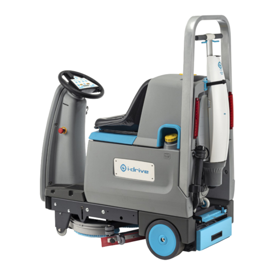
2 Description The i-drive® consists of the following parts: Figure 3 Legend Two tail lights (drive and brake). Two work lights. An i-mop lite (back view). An electromagnetic autobrake. A detergent tank. A squeegee and a vacuum hose. A steering column and steering wheel. -
Page 14: Control Panel On The Steering Wheel
30%. It does not slow down the speed of the i- drive. Reverse touch button. If reverse is activated, the i-drive produces a sound and it drives at a reduced speed. Horn touch button. -
Page 15: Multifunctional Display
1. Indicate battery level (Figure 5, pos 2). 2. Indicate operation time in hours and minutes (Figure 5, pos 1). 3. Indicate i-drive “Ready” (Figure 5, pos 3). 4. Indicate alarm codes, see also section 2.1.2. 5. Indicate "Schedule service". -
Page 16: Codes Alarm Display
2.1.2 Codes alarm display ATTENTION In case an alarm code occurs on the display, please contact service personnel or your i-team partner. Alarm summary table control panel Alarm Description Solution AL_1: Function Brushes ammeter Check brushes motor working current. Excessive and continuous working current Brushes protection. -
Page 17: Solution Level Indicator
2.3.1 The emergency stop The emergency stop button (Figure 7, pos 1) is positioned on the steering column. 1. To activate it, push it in. The i-drive shuts down completely. 2. To start the i-drive again, pull it out. Figure 7... -
Page 18: The Electromagnetic Brake
2.4 Different types of squeegee blades You can order rubber blades or polyurethane blades for the squeegee, depending on the type of surface that you are going to clean with the i-drive. For more information please visit www.i-teamglobal.com. 2.5 Disc brushes and pads You can order disc brushes or pads. -
Page 19: Safety
3 Safety Safety comes first. Therefore, please take time to read and understand these safety instructions. Improper use can cause harm or void the manufacturer’s warranty. 3.1 General safety instructions 3.1.1 Sweep before scrub Remove objects from the floor that can be propelled by the rotating disc brushes. In case of fire, use a powder extinguisher instead of water. -
Page 20: Risks During Operation
3.2 Risks during operation 3.2.1 Dress adequately Do not wear a necktie, scarf, or any loose or dangling clothing or jewelry while operating the i-drive®. These can tangle in rotating parts, causing serious injury or death. 3.2.2 Mark the job site The i-drive is designed to leave a dry floor without slippery patches, no additional drying is required. -
Page 21: Transport And Storage
4.3 Transport in a vehicle WARNING DO NOT use the i-mop bar or plastic parts of the i-drive to secure it during transport. It will damage the i-drive. You can transport your i-drive using a truck equipped with a loading ramp with a <18% slope. -
Page 22: Pushing Or Towing The I-Drive
The electromagnetic brake must be released when the i-drive cannot be used due to low battery level or because there are no batteries or other causes. See section 2.3.2. -
Page 23: Assembly And Installation
5. Load the i-mop® lite. Please refer to the i-mop lite manual for assembly instructions. 5.1 Unboxing The i-drive comes in a single delivery. The i-mop® lite is delivered separately in a box. The batteries and the charger are also delivered separately as they can also be used for other i-team products. -
Page 24: Detaching The I-Drive From The Pallet
1. Loosen the metal brackets at the front left and right side (Figure 12, pos 2). 2. Remove the two wooden planks that secure the rear wheels (Figure 12, pos 1). The i-drive is now free to be moved from the pallet. Figure 12 5.2 Assembly 5.2.1 Attaching the disc brushes and brush covers... -
Page 25: Operation
6 Operation ATTENTION Although the tanks in the i-drive® have been carefully cleaned before it is packed, small amounts of plastic debris could be found during the first hours of operation. 6.1 Before you start Check the disc brushes (see section 7.4.4) and squeegee (see section 7.3.3) for wear and tear. - Page 26 Figure 15 5. Pull out the locking pin on the left side (Figure 16, pos 2) of the battery drawer. 6. Push the battery drawer into the i-drive® by the black handle (Figure 16, pos 1) until it locks into place.
- Page 27 7. Turn the ignition key to position "l". 8. Wait a few seconds. The display should indicate 100% and all 10 bars of the battery level display should be visible (Figure 17, pos 1). Figure 17...
-
Page 28: Filling The Detergent Tank
5.5 L of cleaning agent, using a funnel. 4. Replace the filler cap and make sure it seals tight. 5. Put the detergent tank back in the i-drive®, valve first and the handle facing towards you. Figure 18... -
Page 29: Filling The Solution Tank
6.1.3 Filling the solution tank 1. Remove the yellow filler cap (Figure 19, pos 1). Figure 19 2. Place a water hose in the opening (Figure 20, pos 2). 3. While keeping an eye on the solution level indicator (Figure 20, pos 1), fill the tank with a maximum of 58 L of water. -
Page 30: Adjusting The Seat
Figure 21 6.1.5 Personal locker Behind the i-mop lite you can find a personal locker (Figure 22, pos 1) where you can store personal belongings. It can be locked with a key supplied with the i-drive. Figure 22... -
Page 31: Operation Procedure
6.2 Operation procedure 6.2.1 Driving on the jobsite 1. Take place on the seat behind the steering wheel. The i-drive® is designed to run only when an operator is sitting on the seat. 2. Place the ignition key in the key hole (Figure 23, pos 1). - Page 32 6. Choose the desired driving speed: 1 (up to 2.5 km/h), 2 to 5 (2.5 to 4.5 km /h) (Figure 23, pos 2). 7. Gently push the accelerator pedal down (Figure 23, pos 3) to move forward. 8. Lift your feet off the accelerator pedal to brake, the automatic break will stop the machine. CAUTION Take some time to get acquainted with the handling of the machine, note the smaller left turning circle compared to turning right.
-
Page 33: Using Reverse Drive
6.2.2 Using reverse drive ATTENTION When the machine drives in reverse, a reverse signal is given. 1. Make sure the i-drive® is stopped and your foot is off the accelerator pedal. 2. Press push button (Figure 24, pos 1) to select reverse drive. -
Page 34: At The Job Site
6.2.4 At the job site Figure 26 1. Choose the amount of water to use. Push the water touch buttons (Figure 26, pos 7) for more or less water. There are five different levels, see section 2.1. 2. Choose the amount of detergent to use, the level is always proportional to the amount of water. 3. -
Page 35: Working In Eco Mode
6.2.6 Checking the solution level ATTENTION It is important to check the solution level regularly as the i-drive® will shut down the squeegee and disc brushes if the solution level gets to 20%. The solution level can be checked visually on the... -
Page 36: Making An Emergency Stop
6.2.7 Making an emergency stop In case of an emergency, push the emergency stop button (Figure 29, pos 1). It shuts down the machine completely. See section 2.3.1. Figure 29... -
Page 37: Maintenance
For a proper functioning and a long lifespan of the i-drive, it is important to follow the recommended maintenance intervals mentioned in this manual. Maintenance that is not described in this manual should be performed by your i-drive partner. Please make sure to have the model, serial number and the amount of operating hours of the i-drive available when you call a partner. -
Page 38: Checking The Machine Operating Hours
(Figure 31, pos 1). 5. Check the maintenance frequency table in section 7.13 to see which actions should be taken. 6. Turn the ignition key to "0" to switch off the i-drive®. Figure 31... -
Page 39: Maintenance Tasks On The Squeegee
4. Turn the ignition key to position "0" and remove it. Keep the key with you during maintenance. Figure 32 5. Go to the right side of the i-drive®. 6. Remove the vacuum hose from the hose connector (Figure 33, pos 1). 7. Loosen the two rotary knobs (Figure 33, pos 2). -
Page 40: Placing The Squeegee Body Back On The Squeegee Lifting Plate
7.3.2 Placing the squeegee body back on the squeegee lifting plate 1. Position the squeegee body under the i- drive®, line up the rotary knobs with the cutouts in the squeegee lifting plate. 2. Lift the squeegee lifting plate. 3. Slide the rotary knob of the squeegee body, the furthest away from you (Figure 34, pos 1), into the cutout of the squeegee lifting plate (Figure 34, pos 3). -
Page 41: Cleaning, Checking And Replacing The Squeegee Blades
Daily cleaning can be done with the blades in the squeegee body. Clean the edges of the blades with a damp cloth. Only step 1 and step 15 need to be done. 1. To remove the squeegee body from the squeegee lifting plate of the i-drive®, please see section 7.3.1. Removing the back blade (no holes). - Page 42 Removing the front blade (with holes). 5. Loosen the six wing nuts of the front blade (Figure 37, pos 2). 6. Remove the clamping plate of the front blade (Figure 37, pos 3). 7. Remove the front blade (Figure 37, pos 1) from the squeegee body.
- Page 43 15. Do step 5 to 7 in reverse order, start tightening the wing nuts on one side and work to the other side. 16. To replace the squeegee body on the squeegee lifting plate of the i-drive®, please see section 7.3.2.
-
Page 44: The Disc Brushes
7.4 The disc brushes 7.4.1 Removing the disc brushes ATTENTION The supporting bolts are fixed for transportation, please check them and loosen them if they are fixed. 1. Make sure that the ignition key is in position "0" and remove it. Keep it with you during maintenance. -
Page 45: Placing Back The Disc Brushes
7.4.2 Placing back the disc brushes 1. Make sure that the springs (Figure 42, pos 1) are locked into place behind the cams (Figure 42, pos 2). 2. Push the disc brush on the hexagonal nut of the drive shaft (Figure 42, pos 3) and wiggle it until you feel it is in place. -
Page 46: Replacing The Disc Brushes
7.4.4 Replacing the disc brushes ATTENTION Each disc brush has a wear indicator. This is the red bristle group. If the disc brush is worn near to the length of the red bristle group, it needs to be replaced. 1. To remove the disc brushes, please see section 7.4.1. -
Page 47: Cleaning The Recovery Tank
50 gr. Celsius; • make sure that you follow your local regulations with regard to wastewater. 1. Position the backside of the i-drive® in a recovery water disposal area. 2. Turn the ignition key to "0" and keep the key with you during maintenance. - Page 48 5. Release the recovery tank wastewater tube (Figure 47, pos 2) from the clamp (Figure 47, pos 4). 6. Fold the tube so you create a blockage (Figure 47, pos 3). 7. Place the recovery tank wastewater tube above the recovery water disposal drain. 8.
-
Page 49: Cleaning The Separator
7.5.1 Cleaning the separator 1. Turn the yellow cup (Figure 48, pos 2) from the separator (Figure 48, pos 1) anti clockwise to remove it. Figure 48 2. Clean the yellow cup with tap water, above a sink (Figure 49, pos 1). 3. -
Page 50: Cleaning The Recovery Water Inlet
7.5.2 Cleaning the recovery water inlet CAUTION Wear protective gloves when cleaning the recovery water inlet as sharp debris may be attached to it. 1. Remove the recovery water inlet (Figure 50, pos 1). Figure 50 2. Remove the debris by hand and clean it with tap water and a brush (Figure 51, pos 2) above a sink. -
Page 51: Cleaning The Detergent Filter And Detergent Tank
7.6 Cleaning the detergent filter and detergent tank WARNING Make sure that you follow your local regulations with regard to wastewater. 1. Remove the detergent tank by the handle (Figure 52, pos 2) and put it on a level surface. 2. - Page 52 4. Turn the detergent tank upside down. 5. Unscrew the white cap (Figure 54, pos 1), it holds the detergent filter (Figure 54, pos 2) in place. Figure 54 6. Take of the cap and the filter and rinse both with tap water above a sink (Figure 55, pos 1).
- Page 53 Make sure it seals tight. 10. Place the detergent tank back on the i-drive®. 11. Press the tank downward to make sure that the valve (Figure 56, pos 2) is locked onto the detergent tank connector (Figure 56, pos 1).
-
Page 54: Charging The Batteries
7.7 Charging the batteries ATTENTION The batteries with the blue clips are all placed on the left side and the batteries with the grey clips are all placed on the right side. 1. Turn the ignition key to position "0" and keep the key with you during maintenance (Figure 57, pos 1). - Page 55 9. Turn the ignition key to position "l". 10. Wait a few seconds. The display should indicate 100% and all 10 bars of the battery level display should be visible (Figure 60, pos 1). The i-drive is ready for a new working cycle. Figure 60...
-
Page 56: Unloading, Loading And Refilling The I-Mop® Lite
7.8 Unloading, loading and refilling the i-mop® lite 7.8.1 Unloading and loading 1. Loosen the strap holding the i-mop® lite (Figure 61, pos 1). 2. Unlock the blue lock (Figure 61, pos 2). 3. Pull out the ramp and unfold it (Figure 61, pos 3). -
Page 57: Cleaning The I-Mop® Lite Plateau
9. Place the i-mop solution tank back on the i- mop lite. Please refer to the user manual of the i-mop lite. 7.9 Cleaning the i-mop® lite plateau First unload the i-mop lite, see section 7.8.1. Wipe the plateau on which the wheels of the i- mop lite rest (Figure 63, pos 1) with a damp cloth. -
Page 58: Cleaning The Suction Line
7.10 Cleaning the suction line 1. Take place on the seat behind the steering wheel. 2. Turn the ignition key to position "l". After a few seconds the text "Ready" appears on the display (Figure 64, pos 2). 3. Press the push button (Figure 64, pos 1). The squeegee moves to its lowest position. - Page 59 7. Open the lid of the recovery tank. 8. Remove the recovery water inlet (Figure 66, pos 1). 9. Place the water hose in the recovery water inlet and flush the suction line. 10. When the suction line is clean, replace the vacuum hose on the hose connector of the squeegee (Figure 65, pos 1).
-
Page 60: Cleaning The Water Filter
2. The water filter is positioned under the right front side of the i-drive® (Figure 67, pos 1). 3. Turn the cover of the water filter (Figure 67, pos 2) anti-clockwise to remove it. -
Page 61: Damaged Or Worn Parts
The schedule may vary depending on the type of cleaning work carried out. Failure to carry out maintenance as required may cause damage to the i-drive® and may cause a risk for the operator. We offer service packs. For more information please visit www.i-teamglobal.com. -
Page 62: Servicing The I-Drive
7.13.2 Servicing the i-drive WARNING Service tasks on the i-drive may only be performed by a trained expert of an authorized i-team workshop by reference to the machine-specific system maintenance. Service frequency table Every 125 hours Every 250 hours See Service Manual. -
Page 63: Trouble Shooting
8 Trouble shooting Problem Cause Solution No indicator lights up on the panel; Battery connector disconnected. Connect the connector. the motors do not work. Batteries are flat. Charge the batteries. The emergency stop button is still Release it. pressed. No batteries. Insert batteries. -
Page 64: Decommissioning And Disposal
It is the responsibility of the i-drive® owner to dispose of the product. At the end of life, the i-drive still contains valuable resources and needs to be disposed of according to your local laws and regulations regarding recycling of electrical equipment. -
Page 65: Attachments
10 Attachments 10.1 CE Certificate... - Page 66 This document is part of the technical file of the i-drive® and will be available upon request.
Need help?
Do you have a question about the i-drive and is the answer not in the manual?
Questions and answers