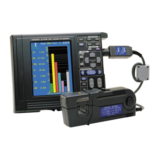
Hioki HiLogger 3145-20 Instruction Manual
Noise search tester
Hide thumbs
Also See for HiLogger 3145-20:
- Instruction manual (190 pages) ,
- Instruction manual (116 pages)

Related Manuals for Hioki HiLogger 3145-20


Summary of Contents for Hioki HiLogger 3145-20
- Page 1 MEASUREMENT GUIDE 3145-20 NOISE HiLOGGER Read first. Offers an introduction to the 3145-20 NOISE HiLOGGER's basic measuring method for first time users.
-
Page 3: Table Of Contents
Contents Contents Introduction __________________________________ 1 Verifying Package Contents _________________ 3 Preparing the Measuring Instrument ________ 4 Checking Noise on the Monitor Display _____ 8 View/Save Noise Progression ______________10 Noise Suppression __________________________18 Measurement Hints _________________________19 Sound Alarm When Exceeding Specified Value ....19 Specifying Recording Time ..........22 Attaching an Event Marker to a Waveform ......22 Index... - Page 4 Contents...
-
Page 5: Introduction
Introduction Introduction Thank you for purchasing the HIOKI "Model 3145-20 NOISE HiLOG- GER." To obtain maximum performance from the instrument, please read this manual first, and keep it handy for future reference. The following instruction manuals are included with the 3145-20 NOISE HiLOGGER. - Page 6 Introduction Notation Safety The following symbols in this manual indicate the relative importance of cautions and warnings. Symbols Indicates that incorrect operation presents an extreme hazard that could result in serious injury or death to the user. Indicates that incorrect operation presents a significant hazard that could result in serious injury or death to the user.
-
Page 7: Verifying Package Contents
Verifying Package Contents Verifying Package Contents Please check to make sure that no items are missing from your package. Model 3145-20 NOISE HiLOGGER..1 Carrying case ........1 Strap............1 CD (Software, Instruction Manuals) Accessories ..............1 Model 9418-15 AC ADAPTER....1 •... -
Page 8: Preparing The Measuring Instrument
Preparing the Measuring Instrument Preparing the Measuring Instrument Install the instrument. • Vents must not be obstructed. 10 cm or more • The instrument should be operated only with the bottom side down- wards. • Do not place on an unstable stand or on an incline. - Page 9 Preparing the Measuring Instrument Connect the 9418-15 AC ADAPTER to the instrument. Plug the AC adapter into the power outlet. Lower Panel Power Outlet AC Adapter • Turn the instrument off before connecting the AC adapter to the instrument and to AC power. •...
- Page 10 Preparing the Measuring Instrument Connect the BNC connector of the 9754 CLAMP ON NOISE SENSOR (optional) to the input terminal of the instrument being connected to. Line up Line up Turn until it clicks Pull the slider on the sensor to open the clamp. Barrier •...
- Page 11 Preparing the Measuring Instrument Clamp the conductor to be measured and close the clamp. Make sure also that the conductor is clamped in the center of the clamp opening. Press on the slider until it clicks to lock shut. Press the sensor slider until the "UN- LOCK"...
-
Page 12: Checking Noise On The Monitor Display
Checking Noise on the Monitor Display Checking Noise on the Monitor Display An example of taking measurements of a PC's commu- nications line (LAN line) is explained here. In order to investigate the cause of a malfunctioning PC, measure the noise current flowing through the LAN cable with the instrument. - Page 13 Checking Noise on the Monitor Display Press to select the range. Set to [200mA] “U.F.” indicates underflow. If “U.F.” is displayed, lower the range. “O.F.” indicates overflow. If “O.F.” is displayed, raise the range. Peak Bar: Displays the noise level’s peak value generated during the monitor display.
-
Page 14: View/Save Noise Progression
View/Save Noise Progression View/Save Noise Progression Measure the noise level's temporal change using the logging function and save it to the PC card. After measuring, check the noise generation time and noise level so that you can gain clues for noise suppression. Setting the measurement conditions Press to open the Set up screen. - Page 15 View/Save Noise Progression Press to move the blinking cursor to [Interval], and press to open the selection window. Recording interval 1s, 2s, 5s, 10s, 20s, 30s, 60s Press to select the recording interval, and to set. Set to . Data will be loaded every second. [1s] How to decide the recording interval When you set the recording time to 1 second, with using the 9726 PC...
- Page 16 View/Save Noise Progression Setting automatic save Set for saving measurement data to the PC card. Press to move the blinking cursor to [AutoSave], and press open the selection window. Selectable Explanations items Does not save data. Auto saves in binary format readable by the instrument and the "DATA VIEWER for 3145 Form...
- Page 17 Important Use only PC Cards sold by Hioki. Compatibility and performance are not guaranteed for PC cards made by other manufacturers. You may be unable to read from or save data to such cards.
- Page 18 View/Save Noise Progression Press to open the initialize screen. Press to move the blinking cursor to [Method], and press to open the contents. Selectable Explanations items The PC Card is not tested for Quick bad sectors. The PC Card is tested for bad sectors, which are removed from use if possible.
- Page 19 View/Save Noise Progression Starting and stopping measurements Start measurements. Measurement data is saved automatically to the PC card. Press and display the Logging screen. Press and start measurements. Press and set the temporal axis. Set to . On the horizontal axis 1 square will become 10 seconds. [10s/DIV]...
- Page 20 View/Save Noise Progression Press the when you wish to view the latest value on the Logging screen. On the updated value display, the updated recorded data for each band's noise level is displayed on the left side of the screen. Press the when you wish to view the maximum value.
- Page 21 View/Save Noise Progression Analyzing data after measurements During logging measurements or after logging ends, check the past logging data by scroll- ing the waveform. You can also check the value for the time the noise occurred. When you wish to view the past waveform, press and set the switching SCRL].
-
Page 22: Noise Suppression
Noise Suppression Noise Suppression Select noise suppression parts based on the noise current data obtained by the measure- ments and perform noise suppression. Noise suppression parts example After performing noise suppression, recheck the LAN cable's noise current level on the instrument's monitor display. -
Page 23: Measurement Hints
Measurement Hints Measurement Hints Sound Alarm When Exceeding Specified Value Set the alarm function and alarm to ON on the Set up screen. Press to open the Set up screen. Press to move the blinking cursor to [Alarm], and press to open the selection window. - Page 24 Measurement Hints Press to move the blinking cursor to [Beep], and press to open the selection window. Selectable Explanations items When the measurement value exceeds the alarm judgment value, the alarm sound sounds. The alarm sound does not sound. Press to select [ON], and press to set.
- Page 25 Measurement Hints Press to move the blinking cursor to [Ref. Level] and press open the selection window. Input type Setting range Current 28.0 A to 2.00 mA μ Voltage 1.40 V to 100 Press to select the reference value, and to set.
-
Page 26: Specifying Recording Time
Measurement Hints Specifying Recording Time When you wish to specify the recording time, set the recording time to on the Set up [Time] screen, and set an optional time. Selectable Explanations items The recording time can be set to Time any value. - Page 27 HIOKI 3145-20 NOISE HiLOGGER Measurement Guide Publication date: July 2007 Edition 1 Edited and published by HIOKI E.E. CORPORATION Technical Support Section All inquiries to International Sales and Marketing Department 81 Koizumi, Ueda, Nagano, 386-1192, Japan TEL: +81-268-28-0562 / FAX: +81-268-28-0568 E-mail: os-com@hioki.co.jp...
- Page 28 HEAD OFFICE 81 Koizumi, Ueda, Nagano 386-1192, Japan TEL +81-268-28-0562 / FAX +81-268-28-0568 E-mail: os-com@hioki.co.jp / URL http://www.hioki.com/ HIOKI USA CORPORATION 6 Corporate Drive, Cranbury, NJ 08512, USA TEL +1-609-409-9109 / FAX +1-609-409-9108 3145A983-00 07-07H Printed on recycled paper...
Need help?
Do you have a question about the HiLogger 3145-20 and is the answer not in the manual?
Questions and answers