
Related Manuals for Hioki 3158


Summary of Contents for Hioki 3158
- Page 1 3158 Instruction Manual AC WITHSTANDING VOLTAGE HiTESTER Mar. 2019 Revised edition 12 3158A981-12 19-03H...
-
Page 3: Table Of Contents
2.8 Installation of the Unit 2.9 Connection to the Measured Equipment 2.10 Startup Inspection Chapter 3 Testing Method 3.1 State of the 3158 and Preset Parameters 3.2 Making Testing Arrangements (in READY State) 3.2.1 Selecting an Output-Voltage Range 3.2.2 Key-lock Function 3.2.3 Initial Settings for Optional Functions... - Page 4 3.5.3 "FAIL" State 3.5.4 Screening in "FAIL" State Chapter 4 Optional Functions 4.1 PASS Hold Function 4.2 FAIL Hold Function 4.3 Hold Function 4.4 Momentary Out 4.5 Double Action 4.6 FAIL Mode 4.7 RS Command [START] 4.8 Inter-lock Function 4.9 Voltage Comparator Position 4.10 Example of Optional Function Settings 4.11 Example of Optional Functions Use Chapter 5 Saving/Loading Preset Values...
- Page 5 Chapter 8 Maintenance and Inspection 8.1 Maintenance 8.2 Fuse Replacement 8.3 Troubleshooting 8.4 Displaying Errors 8.5 Resetting the System 8.6 External Dimensions Chapter 9 Specifications 9.1 Basic Specifications 9.2 General Specifications Appendix APPENDIX1 9613 REMOTE CONTROL BOX (SINGLE) APPENDIX1 9614 REMOTE CONTROL BOX (DUAL) APPENDIX2 9615 H.V.
- Page 7 HIOKI cannot be responsible for losses caused either directly or indirectly by the use of the 3158 with other equipment, or if ownership is transferred to a third party. Before using the product, make sure that the insulation on the test leads is NOTE undamaged and that no bare conductors are improperly exposed.
-
Page 8: Safety Notes
──────────────────────────────────────────────────── Safety Notes Thisproduct is designed to comply with IEC 61010 Safety Standards, and DANGER has been thoroughly tested for safety prior to shipment. However, mishandling during use could result in injury or death, as well as damage to the product. However, using the product in a way not described in this manual may negate the provided safety features. - Page 9 ──────────────────────────────────────────────────── The following symbols in this manual indicate the relative importance of cautions and warnings. Indicates that incorrect operation presents an extreme hazard that DANGER could result in serious injury or death to the user. Indicates that incorrect operation presents a significant hazard WARNING that could result in serious injury or death to the user.
-
Page 10: Notes On Use
・ Replace the fuse only with one of the specified characteristics and voltage and current ratings. Using a non-specified fuse or shorting the fuse holder may cause a life-threatening hazard. Fuse type: 250VT8AL(3158-01) 250VT4AL(3158-03 to 3158-05) ──────────────────────────────────────────────────── Introduction... - Page 11 ・ In the event that the equipment malfunctions in any manner during use, turn off the power immediately, and contact your dealer or HIOKI representative. ・ To avoid electric shock, do not exceed the lower of the ratings shown on the instrument and test leads.
-
Page 12: Contents And Indications Of This Manual
──────────────────────────────────────────────────── Contents and Indications of This Manual Chapter 1: Overview Describes an overview, features, and the names and functions of the parts of the unit. Chapter 2: Testing Arrangements Describes particulars of testing arrangements. Chapter 3: Testing Method Describes procedures for setting, testing, and test results judgment. Chapter 4: Optional Functions Describes procedures for setting optional functions. -
Page 13: Chapter 1 Overview
──────────────────────────────────────────────────── Chapter 1 Overview ────────────────────────────────────────────────────... -
Page 14: Product Introduction
BOX (DUAL) can be connected to the external switch terminal to perform 3158 start/stop control. (7) External I/O The external I/O terminal generates signals according to the state of the 3158. It can be used to feed signals for the start and stop key. (8) RS-232C interface as a standard feature Automatic testing and saving of the test results are possible with the use of a computer. -
Page 15: Names And Functions Of Parts
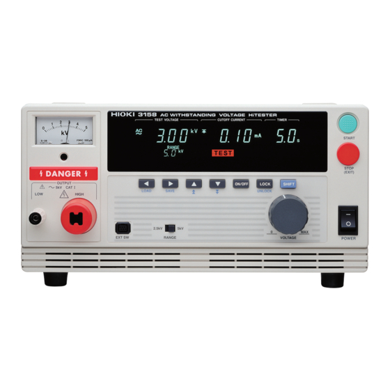
──────────────────────────────────────────────────── 1.2 Names and Functions of Parts Front panel 1 Analog voltmeter Indicates output voltage. 2 Danger Lamp This lamp lights to warn that voltage is present between the terminals during testing. When the DANGER lamp is lit, never touch the HIGH terminal, probe, or tested object. - Page 16 SHIFT key. 11 Output Voltage Knob Sets the output voltage. 12 Main power switch Powers the 3158 on or off. Rubber keys 1 Left/Right cursor key Moves the flashing cursor. The switching range is preset before shipment: Preset Comparative voltage value Upper limit Value Test time.
- Page 17 Used for buzzer sound adjustment. Two knobs are provided: one for PASS screening and one for FAIL screening. 6 External I/O terminal For output of 3158 state and input of start and stop signals. ──────────────────────────────────────────────────── 1.2 Names and Functions of Parts...
- Page 18 ──────────────────────────────────────────────────── 9615 H.V. TEST LEAD High-voltage side (red) Low-voltage side (black) 1 Alligator clip Connect to a test point on the tested object. Vinyl shield on 9615 H.V. TEST LEAD alligator clip is not high voltage insulated. DO NOT touch when high voltage is applied. 2 High-voltage output plug Connect to the HIGH terminal on the unit.
-
Page 19: Chapter 2 Testing Arrangements
──────────────────────────────────────────────────── Chapter 2 Testing Arrangements 2.1 Connecting the Protective Ground Terminal ・ To avoid electric shock, be sure to connect the protective ground WARNING terminal to a grounded conductor. ・ To avoid electric shock, connect the protective ground terminal to a grounded conductor before making any other connections. -
Page 20: Wearing Rubber Gloves
H.V. Test Lead, etc. 1. To avoid electrocution, always wear high-voltage protective rubber gloves when using this product. 2. Contact your dealer or Hioki representative to help you look for high-voltage protective rubber gloves. ──────────────────────────────────────────────────── 2.2 Wearing rubber gloves... -
Page 21: Connecting The External I/O Connector
──────────────────────────────────────────────────── 2.3 Connecting the External I/O Connector ・ Always turn both devices OFF when connecting and disconnecting an WARNING interface connector. Otherwise, an electric shock accident may occur. ・ To avoid electric shock or damage to the equipment, always observe the following precautions when connecting to external I/O. -
Page 22: Power Cord Connection
──────────────────────────────────────────────────── 2.4 Power Cord Connection ・ The rated power voltage for the 3158 varies depending on the WARNING settings of the unit. Before turning on the power, make sure that the voltage of the power supply being used matches the supply voltage indicated on the rear panel of the unit. -
Page 23: Powering On And Off The Unit
──────────────────────────────────────────────────── 2.5 Powering On and Off the Unit Before turning the product on, make sure the source voltage matches WARNING that indicated on the product's power connector. Connection to an improper supply voltage may damage the product and present an electrical hazard. -
Page 24: Connecting The 9615 H.v. Test Lead
Hioki representative for repair. ・ To avoid electric shock, make sure the 9615 H.V. TEST LEAD is securely connected before starting a test, as a loose test lead can cause a hazard when a voltage is output. - Page 25 ──────────────────────────────────────────────────── (1) Remove the LOW terminal by turning it counterclockwise. Low terminal (2) As shown in the figure, insert the plug on the low-voltage test lead. (3) Secure the LOW terminal by turning it clockwise. (4) Connect the plug on the high-voltage test lead to the HIGH terminal. Plug on the low-voltage test lead Plug on the high-voltage test lead ────────────────────────────────────────────────────...
-
Page 26: Connecting The Remote Control Box
──────────────────────────────────────────────────── 2.7 Connecting the REMOTE CONTROL BOX ・ To prevent electrical shock, turn off the power unit and tested object, WARNING make sure that there is no high voltage being applied to the output, confirm the following 3 items, and connect the remote-control box. (1) The analog voltmeter reads 0 kV. -
Page 27: Installation Of The Unit
──────────────────────────────────────────────────── 2.8 Installation of the Unit Install the unit on a stable surface using the four rubber feet on the bottom of the unit. Install on a stable surface using the four stands on the bottom of the unit. (1) Temperature 0 to 40℃, 23±5℃ recommended for high-precision measurements. -
Page 28: Connection To The Measured Equipment
──────────────────────────────────────────────────── 2.9 Connection to the Measured Equipment To avoid any life-threatening electric shock accidents, ensure that the DANGER following rules are observed. ・ The AC Withstanding Voltage HiTester is a dangerous product which discharges high voltages. To prevent getting electrocuted, always wear high-voltage protective rubber gloves when carrying out any operation. -
Page 29: Startup Inspection
──────────────────────────────────────────────────── 2.10 Startup Inspection To ensure safe testing, check the following before starting operation: Breaking current (1) Calculate the resistance based on the output voltage to be set and the upper level value, and then provide a resistor suitable for the resistance. (Output voltage ÷... - Page 30 ──────────────────────────────────────────────────── ──────────────────────────────────────────────────── 2.10 Startup Inspection...
-
Page 31: Chapter 3 Testing Method
──────────────────────────────────────────────────── Chapter 3 Testing Method This chapter describes the procedural flow for testing, making settings, and proper testing procedure. Read Chapter 2, "Testing Arrangements" and make the necessary arrangements for testing. Press keys to display the Optional function setting screen. SHIFT STOP Setting the optional functions allows testing under various conditions. -
Page 32: State Of The 3158 And Preset Parameters
──────────────────────────────────────────────────── 3.1 State of the 3158 and Preset Parameters The 3158 is in one of the following five states: READY state READY 「READY 状態」 The unit is ready for starting a test. The lamp is turned on. To enter TEST state, press the key while in READY state. - Page 33 READY state. The FAIL state can be maintained if the FAIL Hold function is disabled in the optional settings. To return to the READY state, press the STOP key, which will cancel the FAIL Hold function. ──────────────────────────────────────────────────── 3.1 State of the 3158 and Preset Parameters...
-
Page 34: Making Testing Arrangements (In Ready State)
──────────────────────────────────────────────────── 3.2 Making Testing Arrangements (in READY State) In the READY state, the unit is always ready to start a test. The unit can be shifted to the SETTING state only when it is in the READY state. READY lamp remains lit to indicate READY state. Saving and loading for setting data and the setting of optional functions are made following the READY state. -
Page 35: Selecting An Output-Voltage Range
──────────────────────────────────────────────────── 3.2.1 Selecting an Output-Voltage Range The output voltage set using the output-voltage knob nearly doubles WARNING when the output-voltage range is changed from 2.5 kV to 5.0 kV. Conversely, if the range is changed from 5.0 kV to 2.5 kV, the output voltage is reduced by approximately half. -
Page 36: Initial Settings For Optional Functions
Settings are made by changing the number by using the keys. For more information on the settings, see Chapter 4, "Optional Functions." The optional functions of the 3158 are factory-preset to the following settings: Setting item Initial setting... -
Page 37: Setting The "Setting" State
──────────────────────────────────────────────────── 3.3 Setting the "SETTING" State To change settings, switch to the SETTING state. In the READY state, press the keys. The flashing cursor will then appear at the position where the comparative voltage is indicated to show that the unit is in the SETTING state. The READY light will go out. -
Page 38: Setting The Comparative Voltage Value
──────────────────────────────────────────────────── 3.3.1 Setting the Comparative Voltage Value If a comparative-voltage value is to be set, value settings must be made. Once a comparative-voltage value is set, a test will not start until the output voltage reaches the comparative-voltage range, which is ±5% of the comparative-voltage value TEST (output voltage: ≦1 kV :±50 V). -
Page 39: Setting The Upper (Lower) Level Value
──────────────────────────────────────────────────── 3.3.2 Setting the Upper (Lower) Level Value Upper (Lower) level value: 20 mA (1) If the flashing cursor does not appear in the READY state, display the cursor at the position where the Upper-Level Value (Lower-Level Value) is indicated by pressing the keys. -
Page 40: Setting The Test Time
──────────────────────────────────────────────────── 3.3.3 Setting the Test Time Test Time: 60.0s Test Time: OFF (1) If the flashing cursor does not appear in the READY state, display the cursor at the position where the Test Time is indicated by pressing the keys. (2) Set the test time using the keys. -
Page 41: Examples Of Settings
The following shows an example of a test at a comparative-voltage value of 2.00 kV and an upper-level value of 20 mA, with the lower-level value set to OFF, at a test time of 60.0 s. The 3158 is in the READY state. Values currently set... - Page 42 ──────────────────────────────────────────────────── (2) Setting the comparative-voltage value The comparative-voltage value is initially set to OFF. It must be changed to ON before the value is changed. To do so, press the key. ON/OFF The comparative-voltage value in the OFF state is displayed. In this example, the value is 1.50 kV.
- Page 43 ──────────────────────────────────────────────────── The lower-level value is set at 40 mA. Turn it OFF, as it is not needed. To change to OFF, press the key. ON/OFF (5) Setting the test time Using the key, move the flashing cursor to the test time. In this example, change the test time from 120 s to 60.0 s.
-
Page 44: Starting A Test
──────────────────────────────────────────────────── 3.4 Starting a Test The flowchart below explains how a test is carried out. Setting the "READY" state 「READY 状態」での設定 Output Voltage Range Refer to 3.2.1 Refer to 3.2.2 Key-lock Function Refer to Chapter 4 Optional Function Setting the "SETTING" state Comparative Voltage Value Refer to 3.3.1 Refer to 3.3.2... -
Page 45: Setting The Output Voltage
──────────────────────────────────────────────────── 3.4.1 Setting the Output Voltage To avoid any life-threatening electric shock accidents, ensure that the DANGER following rules are observed. ・ The AC Withstanding HiTester is a dangerous product which discharges high voltages. To prevent getting electrocuted, always wear high-voltage protective rubber gloves when carrying out any operation. - Page 46 ──────────────────────────────────────────────────── Set an output voltage using the output-voltage knob. Range Selection Switch Output voltage knob NOTE If you turn the output-voltage knob fully clockwise, the voltage may exceed the set output-voltage range. ■Rated time for output voltages (at an ambient temperature of 40℃) The transformer capacity of the unit is approximately half the rated output.
-
Page 47: Executing A Test
──────────────────────────────────────────────────── 3.4.2 Executing a Test To avoid any life-threatening electric shock accidents, ensure that the DANGER following rules are observed. ・ The AC Withstanding HiTester is a dangerous product which discharges high voltages. To prevent getting electrocuted, always wear high-voltage protective rubber gloves when carrying out any operation. - Page 48 ──────────────────────────────────────────────────── (3) In a test with a comparative-voltage value set, the test is forcibly terminated when the output voltage deviates by ±5% from the comparative-voltage value (output voltage: ≦ 1 kV: ±50 V). In such a case, UPPER, LOWER, and FAIL will light up.
-
Page 49: Screening In "Test State
──────────────────────────────────────────────────── 3.4.3 Screening in "TEST State" (2) (3) (1) Measured voltage value Indicates the voltage value being output. (2) Upper level value icon and Lower level value icon The symbol appears when the upper level value is set, and the symbol appears when the lower level value is set. -
Page 50: Pass Or Fail Determination
──────────────────────────────────────────────────── 3.5 PASS or FAIL Determination 3.5.1 "PASS" State Even when a test has been terminated, there may still be voltage in WARNING the output-voltage terminal when the DANGER lamp is lit. Before touching the output-voltage terminal, test lead, or tested object, make sure the analog voltmeter is at 0 kV, the DANGER lamp is OFF, and TEST lamp is OFF. -
Page 51: Screening In "Pass" State
──────────────────────────────────────────────────── 3.5.2 Screening in "PASS" State (2) (3) (1) Measured voltage value Indicates the voltage in the PASS state. (2) Upper level value icon and Lower level value icon The symbol appears when the upper level value is set, and the symbol appears when the lower level value is set. -
Page 52: Fail" State
──────────────────────────────────────────────────── 3.5.3 "FAIL" State Even when a test has been terminated, there may still be voltage in WARNING the output-voltage terminal when the DANGER lamp is lit. Before touching the output-voltage terminal, test lead, or tested object, make sure the analog voltmeter is at 0 kV, the DANGER lamp is OFF, and TEST lamp is OFF. - Page 53 ──────────────────────────────────────────────────── Flow of FAIL determination Output voltage Comparative voltage value Testing time when it set up Time Flashing UPPER LOWER ( ) (1) Press the START key to start a test. TEST (2) When a comparative-voltage value has been set, flickers until the output voltage switches to the comparative-voltage range.
- Page 54 ──────────────────────────────────────────────────── FAIL Screening Using the Comparative-Voltage Value Output voltage Comparative voltage value Approximately 5 seconds Time Flashing (1) Press the START key to start a test. TEST will flicker until the output voltage switches to the comparative-voltage range. (3) If the output voltage fails to switch to this range in 5 seconds, the unit switches to the FAIL state and stops outputting a voltage.
-
Page 55: Screening In "Fail" State
──────────────────────────────────────────────────── 3.5.4 Screening in "FAIL" State (2) (3) (1) Measured voltage value Indicates the voltage in the FAIL state (2) Upper level value icon and Lower level value icon The symbol appears when the upper level value is set, and the symbol appears when the lower level value is set. - Page 56 ──────────────────────────────────────────────────── ──────────────────────────────────────────────────── 3.5 PASS or FAIL Determination...
-
Page 57: Chapter 4 Optional Functions
──────────────────────────────────────────────────── Chapter 4 Optional Functions ────────────────────────────────────────────────────... - Page 58 ──────────────────────────────────────────────────── Setting the optional functions allows testing under various conditions. Settings can be made for the following eight optional functions. One number is assigned to each function. Settings are made by changing the number by moving the cursor key. Since improper settings can produce inaccurate results, this chapter explains the correct way to make settings.
- Page 59 ──────────────────────────────────────────────────── (5) Double Action Enable this function to allow testing to start only when the START key is pressed within about 0.5 seconds after the key. STOP 0: Not set (initial setting) 1: Set Selection (6) FAIL Mode Enable this function to restrict hold release to the key on the main unit.
-
Page 60: Pass Hold Function
──────────────────────────────────────────────────── 4.1 PASS Hold Function This function retains the value for the PASS state on test completion. To inactivate the hold function, press the key. The unit reverts to the STOP READY state. If the PASS hold function is not selected, the test result is displayed for about 0.5 second before the unit reverts to the READY state. -
Page 61: Fail Hold Function
──────────────────────────────────────────────────── 4.2 FAIL Hold Function This function retains the value for the FAIL state on test completion. To inactivate the hold function, press the key. The unit reverts to the STOP READY state. If the FAIL hold function is not selected, the test result is displayed for about 0.5 second before the unit reverts to the READY state. -
Page 62: Hold Function
──────────────────────────────────────────────────── 4.3 Hold Function Enable this function to hold the current state when testing is interrupted by the key. STOP To inactivate the hold function, press the key. The unit reverts to the STOP READY state. If the Hold function is not selected, the unit switches to the READY state upon forced termination of the test. - Page 63 ──────────────────────────────────────────────────── Distinction between the PASS Hold Function, FAIL Hold Function, and ■ Hold Function ・ With a comparative-voltage value set, if the output voltage deviates from the comparative-voltage range, the unit switches to the FAIL state. ・ If the test time is set to OFF, PASS screening is not performed. In such a case, FAIL screening is performed or the test is terminated using the key.
-
Page 64: Momentary Out
──────────────────────────────────────────────────── 4.4 Momentary Out The momentary out function allows current output only while the START key is held down. Releasing the key is equivalent to pressing the START STOP and ends the test. To perform PASS/FAIL screening, hold down the key until the preset test START time elapses. -
Page 65: Double Action
──────────────────────────────────────────────────── 4.5 Double Action READY If the Double Action function is set, will not light up in the READY state. READY only lights up for approximately 0.5 seconds after the key is STOP READY pressed. While is lit, press the key to start a test. -
Page 66: Fail Mode
──────────────────────────────────────────────────── 4.6 FAIL Mode Enable this function to restrict hold release to the STOP key on the main unit. Setting procedure (1) Press SHIFT STOP keys while in READY state to display the Optional function setting screen. (2) Use the keys to move the flashing cursor to the position shown in the figure. -
Page 67: Rs Command [Start]
──────────────────────────────────────────────────── 4.7 RS Command [START] When RS-232C is used for control, settings can be made to specify whether to accept the test start command ":STAR." If "1: Set" is selected, a test is started when the ":STAR" command is received. If "0: Not set"... -
Page 68: Inter-Lock Function
──────────────────────────────────────────────────── 4.8 Inter-lock Function Settings can be made to specify whether to use the Inter-lock function with the external I/O terminal. If "0: Not set" is selected, the Inter-lock function is cancelled regardless of the state of Pin 10 on the external I/O terminal. If "1: Set"... -
Page 69: Voltage Comparator Position
──────────────────────────────────────────────────── 4.9 Voltage Comparator Position When performing a voltage test, you can select whether you want to view the output-voltage when the test starts, or when the test ends. If "0: Start test" is selected, the Voltage Comparator function is active immediately before and during the withstand voltage test. -
Page 70: Example Of Optional Function Settings
──────────────────────────────────────────────────── 4.10 Example of Optional Function Settings Assume that the 3158 is in the READY state, with the PASS Hold function and FAIL Hold function disabled. The following example shows how to activate the two functions: (1) While holding down the... -
Page 71: Example Of Optional Functions Use
──────────────────────────────────────────────────── 4.11 Example of Optional Functions Use The following describes how 3158 optional functions are used in testing. Varying combinations of optional functions are available for testing. (1) Testing to check test results, using the 3158 Optional function settings Optional function... - Page 72 ──────────────────────────────────────────────────── ──────────────────────────────────────────────────── 4.11 Example of Optional Functions Use...
-
Page 73: Chapter 5 Saving/Loading Preset Values
──────────────────────────────────────────────────── Chapter 5 Saving/Loading Preset Values ────────────────────────────────────────────────────... -
Page 74: Saving Preset Values
──────────────────────────────────────────────────── 5.1 Saving Preset Values The following describes a function used to save values set in the READY state. Up to twenty parameters may be saved. To retrieve saved data, follow the procedures described in Section 5.2, "Loading Preset Values." (1) Comparative voltage value Shows the preset comparative voltage value for the set data being displayed. -
Page 75: Procedure For Saving Data
──────────────────────────────────────────────────── 5.1.1 Procedure for Saving Data To select a preset value to be saved, the unit must be in the READY state. Preset values cannot be changed in the save screen. The following four parameters may be saved: (1) Comparative voltage value (2) Upper level value (3) Lower level value (4) Test time... -
Page 76: Example Of Saving
──────────────────────────────────────────────────── 5.1.2 Example of Saving The following example shows how to save in File No.3. We assume that the 3158 is in the READY state. (1) In the READY state, set the preset value to save. For more information on making these settings, see Chapter 3, "Testing Method."... - Page 77 ──────────────────────────────────────────────────── (3) Use the keys to select File No.3. This example shows File No. 1. Press the key twice to display File No.3. (4) Use the keys to check upper and lower level values. In this example, File No. 3 contains the following settings. Comparative voltage value Upper level value 100 mA...
-
Page 78: Loading Preset Values
──────────────────────────────────────────────────── 5.2 Loading Preset Values The following describes how to load saved data. Twenty preset values may be saved. Use this function to instantly change a preset value. (1) Comparative voltage value Shows the preset comparative voltage value for the set data being displayed. (2) Upper level value icon and Lower level value icon The symbol appears when the upper level value is displayed, and the symbol... -
Page 79: Procedure For Loading Data
──────────────────────────────────────────────────── 5.2.1 Procedure for Loading Data Before loading, carefully read Section 5.1, "Saving Preset Values" and prepare the data to be saved. The following are factory-set data. Comparative voltage value OFF(0.00 kV) Upper level value 0.2 mA Lower level value OFF(0.1 mA)... -
Page 80: Example Of Loading
──────────────────────────────────────────────────── 5.2.2 Example of Loading The following example shows how to load File No.3. We assume that the 3158 is in the READY state. (1) Press keys to bring up the load screen. SHIFT In the load screen, the value set in the READY state is replaced by the saved data being displayed. - Page 81 ──────────────────────────────────────────────────── (3) Use the keys to check upper and lower level values. In this example, File No. 3 contains the following settings. Comparative voltage value Upper level value 20 mA Lower level value 1.0 mA Test time 4.0 s (4) To load the data, press SHIFT + keys.
- Page 82 ──────────────────────────────────────────────────── ──────────────────────────────────────────────────── 5.2 Loading Preset Values...
-
Page 83: Chapter 6 External Interface
──────────────────────────────────────────────────── Chapter 6 External Interface 6.1 External I/O Terminal Both output signals regarding the status of the 3158 (e.g., READY state) and input signals to the key and the key are controlled through the external START STOP I/O terminal, located at the back of the unit. -
Page 84: Signal Line
──────────────────────────────────────────────────── 6.1.1 Signal Line Use the following external I/O connectors or their equivalents: Connector of the 3158 main unit: 57GE-40360-751-FA(DDK Ltd.) Compatible connector : 57-30360 (DDK Ltd.) 57E-30360 (DDK Ltd.) 57F-30360 (DDK Ltd.) 57FE-30360 (DDK Ltd.) External I/O connector pin numbering 18・・・... - Page 85 ──────────────────────────────────────────────────── Function of the signal line Signal line Function name _____ ----------------------- READY LO in the READY state _____ --------------------- L-FAIL LO in the FAIL state at LOWER (minimum value) _____ --------------------- U-FAIL LO in the FAIL state at UPPER (maximum value) _____ --------------------- PASS...
-
Page 86: Example Of Input Signal Connection
──────────────────────────────────────────────────── 6.1.2 Example of Input Signal Connection The unit can be controlled externally using the external I/O input signal. Provide a connector that conforms to the External I/O Specifications. To enable the external I/O signal, set the EXT-E signal (Pin 7) to Lo. Connect the EXT-E signal to ISO.COM for the GND signal (Pins 15 to 18), which is insulated from the unit's internal power supply. - Page 87 ──────────────────────────────────────────────────── (2) Control using the transistor (example) For control using a transistor or FET, make connections as shown below. Design the signals so that 6 mA is absorbed into each of the signals. (Connect the EXT-E signal (Pin 7) and ISO.COM (Pins 15 to 18) to enable external I/O signals.) ISO.DCV Photocoupler...
-
Page 88: Example Of Output Signal Connection
──────────────────────────────────────────────────── 6.1.3 Example of Output Signal Connection The output signal becomes Lo depending on the condition of the unit. Prepare a connector that conforms to the External I/O Specifications. To enable the external I/O signal function, set the EXT-E signal (Pin 7) to Lo. Connect the EXT-E signal to ISO.COM for the GND signal (Pins 15 to 18). - Page 89 ──────────────────────────────────────────────────── (2) Obtaining a signal level (example) To obtain a signal level, make connections as shown below. In addition, check the output current. ISO.DCV Photocoupler ISO.DCV External I/O Terminal ISO.COM The output signal status upon power-on may be undetermined. Care should be taken NOTE in the operation of equipment connected to the external I/O.
-
Page 90: Inter-Lock Function
──────────────────────────────────────────────────── 6.1.4 Inter-lock Function The inter-lock function is used to cut off output from the 3158 in combination with other devices, including external equipment. This function cuts off output from the 3158, and disables all key operations. Setting the inter-lock function ____________ (1) Connect Pin 10 INT.LOCK... - Page 91 ──────────────────────────────────────────────────── Connections for the inter-lock function (example) For example, to ensure the safety of workers, the unit and the tested object are placed in a box so that they are not in contact with each other. The door of the box cover is also equipped with a switch that works in combination with the inter-lock function.
-
Page 92: Timing Chart Of External I/O Terminal
──────────────────────────────────────────────────── 6.1.5 Timing Chart of External I/O Terminal (1) Timing chart at time of start of testing __________ ______ When a test begins, the READY signal becomes HI, and the TEST signal _________ and H.V.ON signal become LO. _______ TEST The TEST signal changes at the same time on the fluorescent indicator... - Page 93 ──────────────────────────────────────────────────── (2) Timing chart during a test decision The figure shows the timing chart of the unit in PASS state after a test. In PASS _______ state, the TEST signal indicates HI. _________ The H.V.ON signal remains at LO provided that the voltage between the output terminals remains unchanged, as the signal is synchronized with the DANGER lamp.
- Page 94 ──────────────────────────────────────────────────── (3) Timing chart at forced termination When the key is pressed to forcibly terminate testing, the unit does not STOP change to either PASS or FAIL status, as test screening is not performed. In this case, the signal becomes HI. In the absence of status indicators (READY/TEST/FAIL/PASS) -- in the SETTING state, when set values are being saved or loaded, or when settings are being made for the optional functions -- all signals become HI.
-
Page 95: Buzzer
──────────────────────────────────────────────────── 6.2 Buzzer A buzzer sounds during PASS or FAIL screening and in the event of an error due to improper key operations. Two buzzer volume adjustment knobs are provided on the rear panel: one for PASS screening and one for FAIL screening. Volume adjustments can be made using the knobs. - Page 96 ──────────────────────────────────────────────────── ──────────────────────────────────────────────────── 6.2 Buzzer...
-
Page 97: Chapter 7 Rs-232C Interface
──────────────────────────────────────────────────── Chapter 7 RS-232C Interface 7.1 Specifications The RS-232C settings of 3158 are as follows. Since the 3158 settings are fixed and cannot be changed, these settings must be matched on the computer side. RS-232C Settings Transmission mode Start-stop synchronization, full duplex... -
Page 98: Connection Method
7.2 Connection Method Use a cross cable for connection to the PC. If the hardware flow control signal (RTS and CTS) is not used, the 3158 will not perform hardware flow control. RTS is connected with CTS in the 3158. -
Page 99: Command Transfer Methods
The command format consists of the command ":STOP" immediately followed by the delimiter. NOTE The meaning of the delimiter is to separate commands and data. When the 3158 receives the delimiter, it starts analysis of the command. ──────────────────────────────────────────────────── 7.3 Command Transfer Methods... - Page 100 NR1, NR2, and NR3. Each has two values: one with a code and one without it. A value without a code is regarded as a positive number. If a number exceeds the accuracy resolution of the 3158, the value is rounded up or down.
-
Page 101: Command
Explains the actions specified by the command. Error Describes errors that may occur when the command is executed. Example > denotes command from the computer. 3158 > denotes command from 3158. NOTE The optional functions cannot be set using an RS command. ──────────────────────────────────────────────────── 7.4 Command... - Page 102 Response OK Resetting completion Function Resets the 3158. The items which are reset are listed below. Comparative voltage value setting: OFF Test time setting: ON, Lower level value setting: OFF Output voltage value: 0.00 kV, Upper level value: 0.2 mA Lower level value: 0.1 mA, Test time: 0.5 s...
- Page 103 Response <data> data 0: OFF 1: ON Function Queries the Comparative voltage value enablement. Example > :VOLT? 3158 > The Comparative voltage value enablement is on. :LOW Enables and disables the lower level value. Syntax :LOW <data> Response Setting completion...
- Page 104 Makes ON/OFF settings for the test time, in the READY or SETTING state. Example Sets the test time to on. > :TIM 1 3158 > Setting completion. Error The execution of this command in a state other than the READY and SETTING state causes an execution error.
- Page 105 In the READY or SETTING state, set the comparative-voltage value. Example Sets the comparative voltage value to 1.50 kV. > :CONF:VOLT 1.50 3158 > Setting completion. Error The execution of this command in a state other than the READY and SETTING state causes an execution error.
- Page 106 In the READY or SETTING state, set the upper level value. Example Sets the upper level value to 5.0 mA. > :CONF:CUPP 5.0 3158 > Setting completion. Error In states other than the READY and SETTING states, or when a value below the comparative-voltage value is set, an execution error occurs.
- Page 107 In the READY or SETTING state, set the lower level value. Example Sets the lower level value to 0.1 mA. > :CONF:CLOW 0.1 3158 > Setting completion. Error In states other than the READY and SETTING states, or when a value below the comparative-voltage value is set, an execution error occurs.
- Page 108 In the READY or SETTING state, set the test time. Example Sets the test time to 1.0 s. Example > :CONF:TIM 1.0 3158 > Setting completion. Error The execution of this command in a state other than the READY and SETTING state causes an execution error.
- Page 109 In the optional functions, if "START" for the RS command is set to "0: Not set," this command will not start testing. Example > :STAR 3158 > Completed. Error The execution of this command in a state other than the READY state causes an execution error.
- Page 110 2: LOWER FAIL 3: READY 4: TEST 5: VOLTAGE SETTING FAIL 6: ELSE Function Queries the state. Example > :STAT? 3158 > State is READY state. :MEAS? Queries the measured value. Syntax :MEAS? Response <data> data Measured voltage value, measured current value, test time elapsed, determination...
- Page 111 :MEAS:VOLT? Response <data> data Measured voltage value( Refer to section 7.5. ) Function Queries the measured voltage value. > Example :MEAS:VOLT? 3158 > Measured voltage value is 1.50 kV. 1.50 :MEAS:CURR? Queries the measured current value. Syntax :MEAS:CURR? Response <data>...
-
Page 112: Transmission And Response Formats
──────────────────────────────────────────────────── 7.5 Transmission and Response Formats The transmission format is identical to the VFD display format, except that the former lacks spaces (" "). The response format is identical to the VFD display format, except that the former lacks spaces (" "). Comparative voltage value, Measured voltage value Transmission and response formats are as follows. -
Page 113: Command Summary
──────────────────────────────────────────────────── 7.6 Command Summary Command Data Explanation Page Queries manufacturer's name, *IDN? model name, and software version. Performs device initial setting. *RST 0: OFF Enables and disables the :VOLT <data> 1: ON Comparative voltage value. Queries the Comparative voltage :VOLT? value enablement. - Page 114 ──────────────────────────────────────────────────── Command Data Explanation Page Queries the lower level value :CONF:CLOW? enablement. 0.5 - 99.9 Sets the test time. :CONF:TIM <data> ( Numerical data in NR2 format, two or three digits ) 100 - 999 ( Numerical data in NR1 format, three digits ) Test time ( Refer to section 7.5.
- Page 115 ──────────────────────────────────────────────────── Chapter 8 Maintenance and Inspection ────────────────────────────────────────────────────...
- Page 116 Hioki representative. ・ Pack the product carefully so that it will not be damaged during shipment, and include a detailed written description of the problem. Hioki cannot be responsible for damage that occurs during shipment. Please refer to "8.3 Troubleshooting" for points to note during transportation.
- Page 117 Replace the fuse only with one of the specified characteristics and voltage and current ratings. Using a non-specified fuse or shorting the fuse holder may cause a life-threatening hazard. Fuse type: 250VT8AL(3158-01) 250VT4AL(3158-03 to 3158-05) (1) Turn the power OFF, and disconnect the power cord.
- Page 118 If any of the following should occur, stop using the unit, disconnect the power cord and probe, and contact your dealer or HIOKI representative. ・ If you are certain that the unit is damaged. ・ If the measurement you wish to perform is inoperative.
- Page 119 ・ When transporting, protect it from strong impact such as dropping it. 8.4 Displaying Errors If an error occurs, the 3158 displays the following on the screen. Err0 Interlock state. (See Section 6.1.4 ) Err1 There is a problem with the external switch.
- Page 120 ──────────────────────────────────────────────────── 8.6 External Dimensions 3 2 0 ±2 ──────────────────────────────────────────────────── 8.6 External Dimensions...
- Page 121 ──────────────────────────────────────────────────── Chapter 9 Specifications 9.1 Basic Specifications Test Voltage Voltage 0 - 2.5 kVAC / 0 - 5.0 kVAC. dual-range configuration Voltage testing method Zero-toggle switch Transformer capacity 500 VA ( maximum 30 min )* Voltage adjustment Manually adjusted with output voltage knob method Voltage measurement Average value rectified effective value display...
- Page 122 ──────────────────────────────────────────────────── Current Detection Section Current measurement 0.01 mA to 120 mA range Designated value Average value rectified effective value display ( digital ) Resolution 0.01 mA (2 mA / 8 mA ranges ) 0.1 mA (32 mA range) 1 mA (120 mA range) ±3 %f.s.
- Page 123 ──────────────────────────────────────────────────── EXT I/O (Rear panel ) : Input/Output signal lines are insulated internally with a photocoupler. Output signal Open collector output Max. load 30 VDC Max. output current 100 mADC per signal Output saturation voltage 1.5 VDC or less Signal names HV-ON : Generating voltage for output TEST : TEST in progress...
- Page 124 ──────────────────────────────────────────────────── Other Functions Memory function The Comparative Voltage Value, urrent determination for upper- and lower-level values, and test time. Storage of up to 20 test conditions allows quick switching between test conditions for different standards. Voltage comparator Testing begins only when voltage is within 5% of the preset value.
- Page 125 Approx. 320W x 155H x 263D mm (12.60"W x 6.10"H x 10.73"D) (excluding projections) Mass Approx. 16 kg (564.4 oz.) (3158-01) Approx. 18 kg (634.9 oz.) (3158-03, -04, -05) Fuse 250VT8AL (3158-01), 250VT4AL (3158-03, -04, -05) Accessories 9615 H.V. TEST LEAD (high voltage side and return, 1 each)
- Page 126 ──────────────────────────────────────────────────── ──────────────────────────────────────────────────── 9.2 General Specifications...
- Page 127 APPENDIX1 ──────────────────────────────────────────────────── Appendix Appendix 1 9613 REMOTE CONTROL BOX (SINGLE) Two types of remote-control boxes are available: the 9613 for use with a single hand and the 9614 for use with both hands. The 9613 REMOTE CONTROL BOX (SINGLE) is equipped with a START key, a STOP key, and an OPERATE switch, which turns ON/OFF the remote-control box.
- Page 128 APPENDIX2 ──────────────────────────────────────────────────── Appendix 2 9614 REMOTE CONTROL BOX (DUAL) Unlike the 9613, the 9614 REMOTE CONTROL BOX (DUAL) has two START keys. Pressing both keys is equivalent to pressing the key on the unit. START By using the Momentary-OUT function in Optional Functions, the 9614 allows the control box to be used with both hands, thus ensuring safer testing.
- Page 129 APPENDIX3 ──────────────────────────────────────────────────── Appendix 3 9615 H.V. TEST LEAD (Standard Accessory) Testing of the grounded lead should be avoided, unless absolutely necessary. If a part such as the lead must be tested, be sure to connect the low-side crocodile clip (black) to the grounded end of the lead. Connecting the high-side crocodile clip (red) to the grounded end of the lead may result in electric shock or damage to the equipment.
- Page 130 APPENDIX4 ──────────────────────────────────────────────────── Appendix 4 Table of Optional Functions The following shows the optional functions. For more information on settings, see Chapter 4, "Optional Functions." Optional function Selection (1) PASS hold function 0: Not held 1: Held (2) FAIL hold function 0: Not held 1: Held (3) Hold function...
- Page 131 INDEX 1 _____________________________________________________________________________________________ Index - A - - F - Alligator clip FAIL hold function 49,51 Analog voltmeter FAIL mode 17,22,37,39,43 54,97 FAIL state File number 62,66 - B - Flashing cursor 4,25,46 Forcible ending Buzzer Fuse 105,109 Buzzer adjustment knob Fuse holder - C - - H -...
- Page 132 INDEX 2 _____________________________________________________________________________________________ - M - - T - Main power switch 4,11 TEST state 35,37,73 Measured current value 37,39,43,99 Test time 28,38,41,42,92,96,107,109 Measured voltage value Test time elepsed 22,37,39,43,99 37,99 Momentary out Timing chart - O - - U - OPERATE switch Upper level value 6,14...
Need help?
Do you have a question about the 3158 and is the answer not in the manual?
Questions and answers