
Subscribe to Our Youtube Channel
Related Manuals for Hioki 3145-20


Summary of Contents for Hioki 3145-20
- Page 1 Instruction Manual 3145-20 NOISE HiLOGGER Contains explanation and instructions regarding the 3145-20 NOISE HiLOGGER’s operating method and functions. April 2013 Revised edition 5 3145A981-05 13-04H...
-
Page 3: Table Of Contents
Contents Contents Introduction.................1 Verifying Package Contents ............2 Safety Information ..............3 Operating Precautions..............5 Chapter 1 Overview __________________________ 7 1.1 Product Overview ............7 1.2 Features ...............8 1.3 Measuring Principle ............9 1.3.1 Monitor Measuring and Logging Measuring ...10 1.3.2 Merits of the Measurement Method of this Instrument ...............11 1.4 Names and Functions of Parts ........12 1.5 Display Screen ............16... - Page 4 Contents Chapter 3 Measurement____________________ 41 3.1 The Measurement Process ........42 3.2 Check the Current Input (Monitor Measurement) ..43 3.3 Record Changes Over Time (Logging Measurement) 45 3.4 "O.F." Display and "U.F." Display ......50 Chapter 4 Useful Functions ________________ 51 4.1 View the Latest Logging Measurement Value or ...
- Page 5 Contents Chapter 6 Saving and Reading Data________81 6.1 Saving Data during Measurement ......82 6.1.1 Select "3145 Form" ..........82 6.1.2 Filenames ...............83 6.1.3 Save Mode ..............84 6.1.4 Specify the File Save Target ........89 6.2 Planning to Save Text after Measurement ....90 6.3 Saving Data after Measurement ........91 6.4 Saving Settings Data ..........94 6.5 Reading Measurement and Settings Data ....97...
- Page 6 Contents 7.2.5 Auto Setup ............126 7.3 Init (Initialization) Screen ......... 127 7.3.1 Setting the Clock ..........127 7.3.2 Erasing Logging Measurement Data ....128 7.3.3 System Reset ............129 7.3.4 Self-check ............. 130 Chapter 8 Using the CD ___________________ 131 8.1 CD Contents ............
-
Page 7: Introduction
Introduction Introduction Thank you for purchasing the HIOKI "Model 3145-20 NOISE HiLOG- GER." To obtain maximum performance from the instrument, please read this manual first, and keep it handy for future reference. The following instruction manuals are included with the 3145-20 NOISE HiLOGGER. -
Page 8: Verifying Package Contents
Hioki representative. • Use the original packing materials when transporting the instrument, if possible. Please check to make sure that no items are missing from your package. Model 3145-20 NOISE HiLOGGER ..1 Carrying case ........1 Strap............1 ... -
Page 9: Safety Information
Safety Information Safety Information This instrument is designed to comply with IEC 61010 Safety Stan- dards, and has been thoroughly tested for safety prior to ship- ment. However, mishandling during use could result in injury or death, as well as damage to the instrument. Using the instrument in a way not described in this manual may negate the provided safety features. - Page 10 Safety Information Others Indicates a prohibited action. Indicates the location of reference information. Indicates quick references for operation and remedies for troubleshooting. Indicates that descriptive information is provided below. Accuracy We define measurement tolerances in terms of rdg. (reading) value, with the following meanings: rdg.
-
Page 11: Operating Precautions
Before using the instrument, make sure that the insulation on the test leads is undamaged and that no bare conductors are improp- erly exposed. Using the instrument in such conditions could cause an electric shock, so contact your dealer or Hioki represen- tative for repair. Installing the instrument °... - Page 12 Never use abra- sives or solvent cleaners. • Hioki shall not be held liable for any problems with a computer system that arises from the use of this CD, or for any problem related to the...
-
Page 13: Chapter 1 Overview
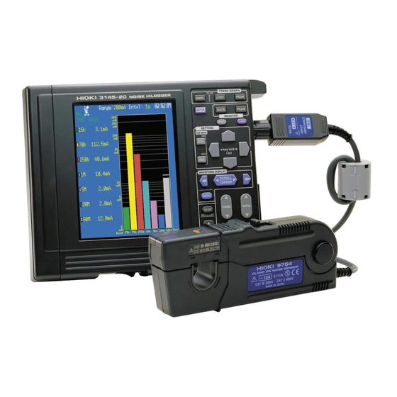
By clamping with the 9754 CLAMP ON NOISE SENSOR the 3145-20 detects noise without touching the sample. Therefore it can perform measurements on instruments in their normal operational state, without worry of communication malfunction due to probe contact, or electrical shock or electrical short circuit accidents from electrical lines. -
Page 14: Features
1.2 Features 1.2 Features Simple and safe measurements With the use of the optional Clamp on Noise Sensor, noise can be measured on power cords, various communications lines, and ground lines without making con- tact or grounding. Wide frequency range (5 kHz - 100 MHz) The instrument is effective for detecting switching regulator noise, inverter noise, electrostatic discharge noise, and FM broadcast wave noise. -
Page 15: Measuring Principle
1.3 Measuring Principle 1.3 Measuring Principle The instrument separates input noise waves into frequency bandwidths using a seven band-pass filter (7 frequency waves) and detects and displays peak values (Peak to Peak values) for each respective frequency range. Center frequency f 15kHz 70kHz 250kHz 1MHz 5MHz 20MHz 60MHz -3dB Attenuation property... -
Page 16: Monitor Measuring And Logging Measuring
1.3 Measuring Principle 1.3.1 Monitor Measuring and Logging Measuring This instrument has two measuring modes, monitor and logging. Monitor measurement The current input levels of each frequency are displayed as a bar graph and numbers. Noise measurement can be made easily in the tester in- terval. -
Page 17: Merits Of The Measurement Method Of This
Banned CB wireless radio Cellular phone 100M 100k Frequency (Hz) The 3145-20 possible measurement range Peak-detection function for capturing surge events Surge incidents of noise such as lightning surges and electrostatic dis- charge noise sometimes occur. Using the instrument's peak function,... -
Page 18: Names And Functions Of Parts
1.4 Names and Functions of Parts 1.4 Names and Functions of Parts Front Panel Display ( p. 16) Key operations Key operations Logging (time series graph) Displays the waveforms on the full screen. Displays the latest value on the left side, and the waveforms on the right side of the screen. - Page 19 1.4 Names and Functions of Parts Key operations (continued) Displays the Set up screen (the screen for setting the measurement condi- tions). Saves an image of the display screen to a PC card. Takes the alarm reference value from the measurement value. Displays the PC card screen.
- Page 20 1.4 Names and Functions of Parts Upper Panel è„ ñþ Eject button PC card slot Ejects the PC card. 10BASE-T Ethernet connection port RS-232C port Connects with a 9642 LAN CABLE. Connects with the 9612 RS-232C CABLE (cross cable for PC use) or the 9721 RS-232C CABLE (straight cable for modem use).
- Page 21 1.4 Names and Functions of Parts Right Panel Input terminal Ventilation holes Connects with the Clamp on Noise Sensor. Bottom Panel Battery box For installing the 9447 BATTERY PACK...
-
Page 22: Display Screen
1.5 Display Screen 1.5 Display Screen 1.5.1 Screen Layout Broadly classified, the instrument has the following 6 different display screen layouts. Logging Monitor Screen Screen • Full • Instanta- • Latest values neous values • Peak values • Peak values (Full screen (Instantaneous shown right) -
Page 23: Logging Screen
1.5 Display Screen 1.5.2 Logging Screen The logging screen has three display types: full screen display, latest value display, and peak value display. Displays the waveforms on the full screen. Displays the peak value on the left Displays the latest value on the left side, and the waveforms on side, and the waveforms and date the right side of the screen. - Page 24 1.5 Display Screen Logging screen Toggle Range Recording interval Time Icon Time axis Event mark Gauge A/B cursor values Band marker Band waveform Time display Icon View Icon Displays various aspects of the instrument's current state. ( p. 22) Gauge The vertical axis of the graph (logarithmic display).
- Page 25 1.5 Display Screen Time Displays the current time. Set using the System Init screen. Time axis The period of time for 1 mass in the time access direction. Use to set. Event mark A mark can be added by pressing during logging measurement.
-
Page 26: Monitor Screen
1.5 Display Screen 1.5.3 Monitor Screen The monitor screen has two display types: instantaneous value display and peak value dis- play. Displays the instantaneous values on the left side, and a bar graph on the right side of the screen. Displays the peak value with its date and time on the left side, and a bar graph on the right side of the screen. - Page 27 1.5 Display Screen Monitor screen Time Icon Range Peak Alarm judgment value Level bar Band display Icon Displays various aspects of the instrument's current state. ( p. 22) Range The measurement range. Use to set. Time Displays the current time. Set using the System Init screen. Alarm judg- The value at which an alarm is triggered at each band when using the ment value...
-
Page 28: Icon Summary
1.5 Display Screen 1.5.4 Icon Summary The following icons are displayed in the upper left of the logging and monitor screens. Icon (Logging screen shown above) Icons Explanations Indicates that the instrument cannot receive commands from the front panel keys (Key lock). Simultaneously pressing for 3 seconds or more will switch between Lock and Unlock. - Page 29 1.5 Display Screen The following icons are displayed in the lower left of the display screen. They indicate the save condition of the measurement data. Icon (Logging screen shown above) Icons Explanations Performing auto save (erase save). Performing auto save (file full). Performing auto save (endless).
-
Page 30: Submenus
1.5 Display Screen 1.5.5 Submenus From the logging display or the monitor display, press to display the submenu. Measurement conditions can be set right on the screen. Press close the submenu. (Logging screen shown here) Submenu Recording time Alarm function Waveform color Event mark ... -
Page 31: Chapter 2 Measurement Preparations
p. 26) Install ferrite cores onto the AC adapter, Clamp on Noise Sensor, and LAN cables. p. 27) Connect the AC adapter to the 3145-20. p. 28) Install the battery pack. p. 29) Charge the battery pack. -
Page 32: Attaching The Strap
2.1 Attaching the Strap 2.1 Attaching the Strap Attach the Strap at attachment point of the instrument. Attach both ends of the Strap securely to the instrument. If insecurely attached, the instrument may fall and be damaged when carrying. Insert each end of the Strap through an attachment point on the instrument. Thread the end of the Strap through the buckle. -
Page 33: Install The Ferrite Cores
• In the case of the Clamp on Noise Sensor, install the ferrite core as close as possible to the termination box. Termination box • In the case of the LAN cable, install the ferrite core as close as possi- ble to the connector which connects to the 3145-20. -
Page 34: Connecting The Ac Adapter
2.3 Connecting the AC Adapter 2.3 Connecting the AC Adapter Connect the AC adapter to the 3145-20 and supply power to the instrument. The 3145-20 can receive power from two types of power sources: either AC adapter or battery pack. -
Page 35: Supplying Power With The Battery Pack
2.4 Supplying Power with the Battery Pack 2.4 Supplying Power with the Battery Pack By using battery power to run the 3145-20 NOISE HiLOGGER, it can be used even in places with no commercial power outlets. The 9447 BATTERY PACK is rated for approximately 1 hour of continuous use (backlight: bright;... -
Page 36: Charging The Battery Pack
2.4 Supplying Power with the Battery Pack 2.4.2 Charging the Battery Pack The battery pack may be charged in the 3145-20 itself, or in the optional 9643 CHARGE STAND. Charging with the 3145-20 NOISE HiLOGGER The 9447 BATTERY PACK can be charged whether the 3145-20's power switch is turned ON or OFF (both during and after measurement). - Page 37 2.4 Supplying Power with the Battery Pack Charging with the optional 9643 CHARGE STAND Place the battery pack in the Charge stand Battery Pack charge stand. Connect the AC adapter to the charge stand. The LED will blink red, and then continu- ally remain lit as rapid charge com- AC Adapter mences.
-
Page 38: Battery Pack Life
2.4 Supplying Power with the Battery Pack 2.4.3 Battery Pack Life If the battery life is considerably short even with correct charging, replace the battery pack with a new one. As the battery pack charge is depleted, the low battery mark will be displayed in the upper left of the logging screen or monitor screen. -
Page 39: Connect The Clamp On Noise Sensor
2.5 Connect the CLAMP ON NOISE SENSOR 2.5 Connect the CLAMP ON NOISE SENSOR Connect the Clamp on Noise Sensor to the terminals of the 3145-20, and clamp the line to be measured. Before using, read the instruction manual included with the Clamp on Noise Sensor and fol- low all safety precautions. - Page 40 2.5 Connect the CLAMP ON NOISE SENSOR To avoid damaging the instrument, do not apply current that exceeds the maximum continuous input range. * Maximum continuous input range: This range is based on heat that is internally generated during sine wave input at a prescribed frequency at room temperature.
- Page 41 2.5 Connect the CLAMP ON NOISE SENSOR Pull the slider on the sensor to open the clamp. Clamp the conductor to be measured and close the clamp. Current direction Make sure that the current direction indi- indicator Current cator arrow matches the direction of cur- rent flow on the conductor being measured.
-
Page 42: Turning The Power On And Off
2.6 Turning the Power On and Off 2.6 Turning the Power On and Off Power On Turns on ( ) the POWER switch. Depending on the type and condition of the power supplied to the instrument, one of the following messages appears on the display. Marks Explanations Operating with the AC adapter. -
Page 43: Using The Pc Card
Card or cause malfunction of the instrument. 2.7.1 Inserting the PC card When saving logging measurement data or setting conditions to a PC card, insert the PC card into the slot at the top of the 3145-20. Important Use only PC Cards sold by Hioki. -
Page 44: Pc Card Initialization
2.7 Using the PC Card 2.7.2 PC Card Initialization Initialize the PC card. All files on the PC card will be erased, and a system file resistant to power outage will be created. When using a PC card with the instrument, be sure to format the card before its initial use using the instrument. - Page 45 2.7 Using the PC Card Press to move the flashing cursor to [Method], and press to open the contents. Selectable Explanations items The PC Card is not tested for Quick bad sectors. The PC Card is tested for bad sectors, which are removed from use if possible.
-
Page 46: Pre-Operation Inspection
2.8 Pre-Operation Inspection 2.8 Pre-Operation Inspection Before beginning measuring, check the following points. Model 3145-20 NOISE HiLOGGER Is the 3145-20 chassis completely free of damage? Are the cables free of any torn insulation or exposed metal? Does the "HIOKI" logo appear on the screen... -
Page 47: Chapter 3 Measurement
Chapter 3 Measurement • The maximum input voltage is 5 V peak. Attempting to measure voltage in excess of the maximum input could destroy the instru- ment and result in personal injury or death. • The maximum rated voltage between input terminals and ground is 5 V. -
Page 48: The Measurement Process
3.1 The Measurement Process 3.1 The Measurement Process Check the current input Record changes over time Monitor measurement ( p. 43) Logging Measurement ( p. 45) Pre-measurement preparations Pre-measurement preparations ( p. 25) ( p. 25) Set the input type. ( p. 74) Set the input type. -
Page 49: Check The Current Input (Monitor Measurement)
3.2 Check the Current Input (Monitor Measurement) 3.2 Check the Current Input (Monitor Measurement) The measurement values for each individual band (15kHz, 70kHz, 250kHz, 1MHz, 5MHz, 20MHz, 60MHz) can be checked on the screen. The data cannot be saved. Make preparations for measurement referring to "Chapter 2 Measurement Preparations"... - Page 50 3.2 Check the Current Input (Monitor Measurement) Press to select the range. Selectable ranges: 200mA, 2A, 20A As a general reference, select 200mA for communications, 2A for power supply and 20A for lightning surge. When checking using voltage levels, set the input type to "Voltage"...
-
Page 51: Record Changes Over Time (Logging Measurement)
3.3 Record Changes Over Time (Logging Measurement) 3.3 Record Changes Over Time (Logging Measurement) With logging measurement, the change over time of the measurement values at each band (15kHz, 70kHz, 250kHz, 1MHz, 5MHz, 20MHz and 60MHz) can be viewed. Make preparations for measurement referring to "Chapter 2 Measurement Preparations"... - Page 52 3.3 Record Changes Over Time (Logging Measurement) Press to select the recording interval. Selectable ranges: 1s, 2s, 5s, 10s, 20s, 30s, 60s Press to change the time axis. Selectable ranges: 2s, 5s, 10s, 20s, 30s, 1min, 2min, 5min, 10min, 20min, 30min, 1h, 2h, 5h, 10h, 12h, 1d The selectable range of the time axis differs depending on the recording interval setting.
- Page 53 • By setting auto save to "Text", after completion of measurement the data which remains in internal memory is auto-saved. ( p. 90) • By setting auto save to OFF, data is saved in the 3145-20 internal memory (32MB). Please note that when the internal memory becomes full, old data is erased.
- Page 54 3.3 Record Changes Over Time (Logging Measurement) Press to commence logging measurement. If auto save mode is set to [Ref. Time], when starting measurement the "Sync fixed time“ message is displayed until the recording interval synchronizes to reference time. Press to view the latest value.
- Page 55 3.3 Record Changes Over Time (Logging Measurement) • If the auto save setting is OFF in the Set up screen, when commenc- ing a new measurement after a prior measurement the recorded data in the internal memory is erased. To retain the data, use the PC card screen to save it to PC card.
-
Page 56: O.f." Display And "U.f." Display
3.4 "O.F." Display and "U.F." Display 3.4 "O.F." Display and "U.F." Display If the measurement value for each frequency wave range is lower than the selected measurement range, "U.F." (Underflow) will be displayed. Alternatively, if the measurement value for each frequency wave range is higher than the selected measurement range, "O.F."... -
Page 57: Chapter 4 Useful Functions
Chapter 4 Useful Functions The 3145-20 NOISE HiLOGGER has the following useful functions. Please make use of them as necessary. Functions Logging Monitor "4.1 View the Latest Logging Measurement Available Value or Peak Value" ( p. 52) "4.2 Check Using a Bar Graph (Monitor Mea- Available surement)"... -
Page 58: View The Latest Logging Measurement Value Or Peak Value
4.1 View the Latest Logging Measurement Value or Peak Value 4.1 View the Latest Logging Measurement Value or Peak Value Displays the latest value on the left Displays the peak value on the left side, and the waveforms on the right side, and the waveforms on the right side of the screen. -
Page 59: View Past Waveforms (Scroll Function)
4.3 View Past Waveforms (Scroll Function) 4.3 View Past Waveforms (Scroll Function) Waveforms on the Logging screen can be scrolled horizontally. Display <Example> Display Scroll Left 4.3.1 Scrolling the Waveform Press and switch the position to [SCRL]. Press to scroll the waveform. Scroll the waveform fast. -
Page 60: Auto Scrolling
4.3 View Past Waveforms (Scroll Function) 4.3.2 Auto Scrolling Holding the for five seconds activates automatic waveform scrolling ("Auto Scroll" is displayed). Press any key to cancel auto scrolling. • During measurement auto scroll cannot be performed. • The amount of time which can be saved (maximum recording time) in the instrument's internal memory differs depending on the recording interval setting, so please refer to "The relationship between recording interval and maximum recording time"(... -
Page 61: A/B Cursor Measurement
4.4 A/B Cursor Measurement 4.4 A/B Cursor Measurement Measurement data at a particular position on a waveform can be read using the A-B cur- sors. The A-B cursor operations are available while measuring. For the values read by the A and B cursors, values outside the measurement range are dis- played as "O.F."... -
Page 62: Using The Alarm Function
4.5 Using the Alarm Function 4.5 Using the Alarm Function If the measurement values at each individual band exceed the alarm judgment values, the following actions are taken as notification. • The alarm state notification icon is displayed on the screen. •... - Page 63 4.5 Using the Alarm Function Press to move the blinking cursor to the reference value position, and press to set it to ON. Press to move the blinking cursor to the value position, and press open the selection window. The band for setting the alarm Press to select the reference value, and to set.
- Page 64 4.5 Using the Alarm Function Set the compensation value Press to move the blinking cursor to [Adj.], and press to open the selection window. Selectable Explanations items Judgment Value = Reference Value x Gain + Offset The reference value is the judg- ment value.
-
Page 65: Setting On The Set Up Screen
4.5 Using the Alarm Function 4.5.2 Setting on the Set Up Screen Press to open the Set up screen. Press to move the blinking cursor to [Alarm], and press to open the selection window. Selectable Explanations items Turns the alarm function ON. Turns the alarm function OFF. - Page 66 4.5 Using the Alarm Function Set the time to continue the alarm When alarm continue is set to ON, the alarm output continues even after one instance of exceeding the alarm judgment value. Alarm output is stopped by stopping measurement. Press on the Set up screen to move the blinking cursor to [Hold], and press...
- Page 67 4.5 Using the Alarm Function Set the alarm sound If the alarm sound is set to ON, when the alarm judgment value is exceeded the alarm sound will be output from the instrument's internal speakers. Press on the Set up screen to move the blinking cursor to [Beep], and press to open the selection window.
- Page 68 4.5 Using the Alarm Function Set the alarm reference value This reference value is used as the alarm function judgment value. It will be used as is for the alarm judgment value if the compensation function is OFF. If the compensation function is ON, the compensated reference value will be the judgment value.
- Page 69 4.5 Using the Alarm Function Set the compensation value To use the alarm reference value as the judgment value, set compensation to OFF. Alter- natively, to calculate the judgment value by compensensating the reference value, turn compensation ON and set the gain and offset. Press on the Set up screen to move the blinking cursor to [Adj.], and press...
- Page 70 4.5 Using the Alarm Function Press to move the blinking cursor to offset value, and press open the selection window. Setting range 0.00 A to 28.0 A Press to select the offset value, and to set. To cancel, press...
-
Page 71: Take The Alarm Reference Value (Monitor Screen)
4.5 Using the Alarm Function 4.5.3 Take the Alarm Reference Value (Monitor Screen) The monitor screen measurement value can be set to the alarm reference value. If the input value exceeds the alarm judgment value, the instrument enters alarm state. Check that the copy key function on the System Env screen is set to "Alarm capture". -
Page 72: Adding Event Marks To Waveforms
Adding an event mark via external signal input Event marks can be added by inputting an external signal into the EXT TRIG input on the lower face of the 3145-20. To do this, set the external trigger input on the System Env screen to "Event". -
Page 73: Searching Event Marks
4.6 Adding Event Marks to Waveforms 4.6.2 Searching Event Marks Each event mark can be searched. Press to display the submenu. Press to move the blinking cursor to the event number, and press to open the selection window. Press to select the event number, and to set. -
Page 74: Highlighting A Specific Band
4.7 Highlighting a Specific Band 4.7 Highlighting a Specific Band In order to more easily view a specific band, all bands other than the selected one are dis- played as gray. Press to enter highlighting display. Press to select the band to be highlight. The highlight band The color of all bands other than the selected band becomes gray. -
Page 75: Preventing Malfunctions (Key Lock)
4.8 Preventing Malfunctions (Key Lock) 4.8 Preventing Malfunctions (Key Lock) This feature disables input from all of the 3145-20's front panel keys. It prevents malfunc- tions during measurement. Press simultaneously for approximately 3 or more seconds to place the instrument in key lock mode. -
Page 76: Saving The Display Screen To Pc Card (Screen Capture)
(Screen Capture) The display screen can be saved to PC card. Check that a PC card is inserted into the 3145-20. Display the screen to be saved. To save the monitor screen, set the copy key in the System Env screen to [Screen capture]. -
Page 77: Setting The Measurement Conditions
Setting the Measurement Chapter 5 Conditions The following measurement conditions can be set with the Set up screen. Press this key to open the Set up screen. Clock (setting can be changed with the System Init screen) Comment ... -
Page 78: Inputting Comments
5.1 Inputting Comments 5.1 Inputting Comments By inputting comments, they will be saved along with the logging measurement data onto the PC card. It can be useful to enter information such as the measurement location. Set the comments only as deemed necessary. Measurement will not be effected even if no comments are entered. -
Page 79: Comment Input Method Details
5.1 Inputting Comments 5.1.1 Comment Input Method Details Comment input window Comment input area Move the cursor to the beginning: Move the cursor to the end: Move the cursor one space to the left or right: Character selection area Move the cursor: Character input: (2) (3) When the cursor is moved to (1) - (7) in the comment input window and... -
Page 80: Setting The Input Type
5.2 Setting the Input Type 5.2 Setting the Input Type Depending on the type of object being measured, you can choose between [Current] (general purpose) input. Select for using general purpose input, such as [Voltage] [Voltage] measuring radiant noise from antennae or measuring noise with a magnetic field probe. Press to open the Set up screen. -
Page 81: Setting The Range
5.3 Setting the Range 5.3 Setting the Range Set the current (or voltage) range. The possible measurement range differs depending on the selected range. Refer to "9.2 Input Area Specifications" ( p. 140) regarding the instrument's range config- uration and measurement range. If the input value exceeds the measurement value, "O.F." (Overflow) will be displayed. -
Page 82: Setting The Recording Interval
5.4 Setting the Recording Interval 5.4 Setting the Recording Interval Sets the interval between each time data is taken. Please select a recording interval which suits the object being measured. Increasing the recording interval causes the maximum recording time to be increased. Regarding the maximum recording time, refer to "The rela- tionship between recording interval and maximum recording time"(... -
Page 83: Setting The Recording Time
5.5 Setting the Recording Time 5.5 Setting the Recording Time Sets the amount of time to record a single logging measurement. The recording time is lim- ited based on the recording interval. Press to open the Set up screen. Press to move the blinking cursor to [Rec. - Page 84 5.5 Setting the Recording Time If set to [Time], continue on to set the recording time. Press to move the blinking cursor to the time to be set, and press open the selection window. Selectable Explanations items 0 to 970 Hour 0 to 23 Minute...
-
Page 85: Setting The Waveform Color
5.6 Setting the Waveform Color 5.6 Setting the Waveform Color Sets the waveform color for each band. Press to open the Set up screen. Press to move the blinking cursor to waveform, and press to open the selection window. Selectable colors Green, yellow, red, light blue, purple, blue and white (For color display) Press... - Page 86 5.6 Setting the Waveform Color...
-
Page 87: Chapter 6 Saving And Reading Data
Setting data Data such as the range, recording time, and time axis data can be saved. As needed, the data can be loaded by the 3145-20 and measure- ment can repeatedly be performed under the same conditions. (File extension: HNS) -
Page 88: Saving Data During Measurement
To cancel, press • The data save interval is one minute. • Data saved in the “3145 Form” is readable by the 3145-20 and the "DATA VIEWER for 3145" software on the included CD. • When using text format, save after measurement completion. -
Page 89: Filenames
6.1 Saving Data during Measurement 6.1.2 Filenames By inputting a filename, auto save files will be saved with that name. Press on the Set up screen to move the blinking cursor to the filename location. Press to open the filename input window. Press to move the cursor to the character to be input, and press select. -
Page 90: Save Mode
6.1 Saving Data during Measurement 6.1.3 Save Mode Normally, the save mode is set to "Normal", "Full". Press on the Set up screen to move the blinking cursor to [File], and press to open the selection window. Selectable Explanations items Carrying out one measurement Normal creates one file. - Page 91 6.1 Saving Data during Measurement <Example> Wave file When selecting "Interval" and the partition length is 1 hour Partition length 7:30 8:30 9:30 10:30 11:30 12:30 13:30 14:30 15:30 (Starting measurement) When selecting "Ref. Time", reference time 8:00 and the partition length is 1 hour Segmental time 12:00 14:00...
- Page 92 6.1 Saving Data during Measurement <Example> Behavior when the PC card reaches full capacity. When [Endless] is selected File being saved The oldest data is overwritten with the new data, and measure- Folder ment continues. When [Delete] is selected File being saved The oldest file in the folder is erased.
- Page 93 6.1 Saving Data during Measurement When selecting “Interval” When selecting , the length of data to partition can be set. [Interval] Press to move the blinking cursor to [Length], and press to open the selection window. Selectable Explanations items 0 to 30 Hour 0 to 23 Minute...
- Page 94 6.1 Saving Data during Measurement When selecting “Ref. time” When selecting , set the length of the data partition and the reference time. [Ref. Time] Press to move the blinking cursor to [Time], and press to open the selection window. Selectable items 1 min, 2 min, 5 min, 10 min, 15 min, ...
-
Page 95: Specify The File Save Target
6.1 Saving Data during Measurement 6.1.4 Specify the File Save Target The folder in which files are saved during auto save is set in the following manner. Press to open the PC card screen. Press to select the folder to move to. To move one folder up, select the ". -
Page 96: Planning To Save Text After Measurement
(32 MB) will be automatically saved to the PC card. Data saved in the text format can be read by software such as personal computer spreadsheet programs. (It cannot be read by the 3145-20.) Press to open the Set up screen. -
Page 97: Saving Data After Measurement
(If measurement data is displayed on the log- ging screen, then the data exists in the internal memory.) • Up to four settings data items can be stored in the 3145-20's internal memory. Refer to "7.2 Setting Screen" ( p. 122). - Page 98 The settings are saved. Auto saves in text format read- Text (for able by personal computer Spread- spreadsheet programs. (Can- sheet) not be read by the 3145-20.) Press to select either [3145 Form] [Text] (for spreadsheet), and press to set.
- Page 99 6.3 Saving Data after Measurement Press to move the blinking cursor to [Same Name], and press open the selection window. Selectable Explanations items This mode saves files with the same name by automatically appending a number after the file name. If the last file was Auto saved with...
-
Page 100: Saving Settings Data
6.4 Saving Settings Data Data such as the range, recording time, and time axis data can be saved. As needed, the data can be loaded by the 3145-20 and measurement can repeatedly be performed under the same conditions. (File extension: HNS) Up to four settings data items can also be saved in the instrument's internal memory. - Page 101 Auto saves in text format read- Text (for able by personal computer Spread- spreadsheet programs. (Can- sheet) not be read by the 3145-20.) Press to select [Set], and press to set. Set the file name. ( p. 83) Press to move the blinking cursor to...
- Page 102 6.4 Saving Settings Data Press to select [Auto] or [Overwrite], and press to set. Press to move the blinking cursor to [Execute] , and press to exe- cute. To cancel, move the blinking cursor to [Back] and press...
-
Page 103: Reading Measurement And Settings Data
The instrument's settings state (HNS file extension) and measurement data (HNW file extension) can be transferred from PC card to the main instrument's internal memory. Data saved in the text format (for spreadsheets) cannot be read by the 3145-20. Press to open the PC card screen. - Page 104 6.5 Reading Measurement and Settings Data Press to open the file read screen. Press again to read the file. If there is too much data to all be read at once, set the amount of data to read and the posi- tion to begin reading.
-
Page 105: File Operation
Reference Command Explanations page Transfers setting conditions and measurement data from p. 97) Load PC card to the 3145-20 main instrument's memory. Saves measurement data and settings data to the PC p. 91) Save card. Delete Deletes files or folders. -
Page 106: Moving Between Folders
6.6 File Operation 6.6.1 Moving between Folders Moving from the current folder to another folder. Press to open the PC card screen. Press to select the folder to move to. To move one folder up, select the ". ." folder. Press to move to the folder. -
Page 107: Deleting Files And Folders
6.6 File Operation 6.6.2 Deleting Files and Folders Delete unnecessary files or folders on the PC card. Press to open the PC card screen. Press to select the measurement data or setting condition, or the folder to be deleted. Press to select the [Delete] command. -
Page 108: Creating Folders
6.6 File Operation 6.6.3 Creating Folders Create folders to be used for saving files. Press to open the PC card screen. Press to select the [Make Fold] command. Press to open the folder creation screen. - Page 109 6.6 File Operation Press to open the input window. Input the folder name, and press to confirm. Refer to "5.1 Inputting Comments" ( p. 72) regarding the input method. Press to move the blinking cursor to [Execute] , and press to exe- cute.
-
Page 110: Changing File Names And Folder Names
6.6 File Operation 6.6.4 Changing File Names and Folder Names Change saved file or folder names. Press to open the PC card screen. Press to select the [Rename] command. Press to select the measurement data or setting data file name which is to be changed. -
Page 111: Changing The File Order
6.6 File Operation 6.6.5 Changing the File Order Change the order in which files on the PC card are displayed. Press to open the PC card screen. Press to select the [Sort] command. Press to open the order change screen, and to open the selection window. -
Page 112: Calculation Method For "3145 Form" Files
6.7 Calculation Method for “3145 Form” Files Press to select sort type, and press to set. Press to move the blinking cursor to [Sort Direction], and press open the selection window. Press to select [Up] or [Down], and press to set. Press to move the blinking cursor to [Execute]... -
Page 113: Content Format For Text Format Files
6.8 Content Format for Text Format Files 6.8 Content Format for Text Format Files Text format files are comprised of a header section and a data section. The header section contains the following information about the measurement data. (Text files are compatible with most spreadsheet software.) (1) Equipment name (2) Comment... - Page 114 6.8 Content Format for Text Format Files Power fault protection while recording to a PC card System files are automatically created for the power fault protection function during initialization (formatting). These files are not displayed in the File selection window, but the symbol is displayed at the bottom of the PC card screen.
-
Page 115: Chapter 7 System Screen
Chapter 7 System Screen The system screen contains 3 screens: environment, setting conditions, and initialize. Press to open the Set up screen, and to move the blinking cursor to [System]. to open the System screen. Press to toggle between the System Env screen, the System Setting screen, and the System Init screen. -
Page 116: Env (Environment) Screen
7.1 Env (Environment) Screen 7.1 Env (Environment) Screen 7.1.1 Start Key Receive Condition (Malfunction Prevention) Normally, pressing once will start measurement, but in order to prevent starting mea- surements accidentally the start key receive condition can be changed to "Two Pushes" or "2s Push". -
Page 117: Start Backup After Power Loss
7.1 Env (Environment) Screen 7.1.2 Start Backup After Power Loss By setting Start backup to ON, if the instrument suddenly loses power, such as by power outage, during logging measurement, recording will restart when the power is turned on again. (The data before the power cut off will be lost.) If Start backup is set to OFF, when the power is cut off the measurement will be canceled and the data recorded up until then will be saved in internal memory. -
Page 118: Grid Type
7.1 Env (Environment) Screen 7.1.3 Grid Type The grid on the display screen can be changed. The three options are: OFF, standard, and Fine. Open the System Env screen. to open the Set up screen Press Press (Press to move to [System] open the System screen ... -
Page 119: Time Format When Saving Text
7.1 Env (Environment) Screen 7.1.4 Time Format when Saving Text Time, date or data number can be selected as the time format of the data when saving in text format. Open the System Env screen. to open the Set up screen Press ... -
Page 120: External Trigger Input (Event Marker)
7.1 Env (Environment) Screen 7.1.5 External Trigger Input (Event Marker) This sets the action to take when the signal input to the external trigger terminal changes from the HIGH level (2.5-5.0 V) to the LOW level (0-1.0 V). The external trigger terminal can be set as an external trigger input signal or as an event marking signal. -
Page 121: External Trigger Filter
7.1 Env (Environment) Screen 7.1.6 External Trigger Filter When the external trigger input is set to "Event", an external trigger filter can be used to pre- vent chattering of the external trigger input. Refer to "Appendix 2 Trigger Terminals" ( p. A2). -
Page 122: Copy Key Function (Monitor)
7.1 Env (Environment) Screen 7.1.7 Copy Key Function (Monitor) This function applies to the copy key being pressed on the monitor display. "Alarm capture" or "Screen capture" can be chosen. On all screens other than the monitor screen, pushing key will effect BMP save. Open the System Env screen. -
Page 123: Save Color
7.1 Env (Environment) Screen 7.1.8 Save Color When saving a BMP image using the key, the display screen can be saved either in grayscale or in color. Open the System Env screen. to open the Set up screen Press ... -
Page 124: Backlight Saver
7.1 Env (Environment) Screen 7.1.9 Backlight Saver When the backlight saver is enabled, the display backlight turns off automatically when no key is pressed for a specific time. The backlight turns on again when any key is pressed. Allowing the backlight to turn off when not needed increases the life of the backlight and operating time per battery charge. -
Page 125: 10Backlight Brightness
7.1 Env (Environment) Screen 7.1.10 Backlight Brightness The brightness of the backlight can be adjusted. Using the instrument with the backlight set to "Dark" lengthens the operation time with the battery pack. Open the System Env screen. to open the Set up screen Press ... -
Page 126: 11Screen Color Scheme
7.1 Env (Environment) Screen 7.1.11 Screen Color Scheme The color scheme of the display screen can be selected. Open the System Env screen. to open the Set up screen Press Press (Press to move to [System] open the System screen Press to open the Env screen) Press to move the blinking cursor to... -
Page 127: 12Display Language
7.1 Env (Environment) Screen 7.1.12 Display Language The display language can be set to either English or Japanese. Open the System Env screen. to open the Set up screen Press Press (Press to move to [System] open the System screen Press to open the Env screen) Press to move the blinking cursor to [Language], and press... -
Page 128: Setting Screen
7.2 Setting Screen 7.2 Setting Screen 7.2.1 Saving Settings All current settings can be saved to internal memory. Up to four setting conditions can be saved. Open the System Setting screen. to open the Set up screen Press Press (Press to move to [System]... - Page 129 7.2 Setting Screen Press to open the comment input window. Press to move the cursor to the character to be input, and press select. Refer to "5.1 Inputting Comments" ( p. 72) for a detailed description of the input method. Once the comment is completely entered, use to move the blinking cursor to [OK].
-
Page 130: Loading Setting Conditions
7.2 Setting Screen 7.2.2 Loading Setting Conditions Previously saved settings conditions can be loaded. Open the system System Setting screen. to open the Set up screen Press Press (Press to move to [System] open the System screen Press to open the Setting screen) Press to move the blinking cursor to... -
Page 131: Deleting Setting Conditions
7.2 Setting Screen 7.2.3 Deleting Setting Conditions Saved setting conditions can be deleted. Open the system System Setting screen. to open the Set up screen Press Press (Press to move to [System] open the System screen Press to open the Setting screen) Press to move the blinking cursor to... -
Page 132: Automatically Loading
7.2 Setting Screen 7.2.4 Automatically Loading Turning power on automatically loads the specified (No.) setting conditions. Open the system System Setting screen. to open the Set up screen Press Press (Press to move to [System] open the System screen Press to open the Setting screen) Press to move the blinking cursor to [Auto], and press... -
Page 133: Init (Initialization) Screen
7.3.1 Setting the Clock The date and time displayed at the upper right of the screen can be changed by taking the following steps. The 3145-20 NOISE HiLOGGER's clock is a 24-hour clock and auto-calen- dar which compensates for leap year. -
Page 134: Erasing Logging Measurement Data
7.3 Init (Initialization) Screen 7.3.2 Erasing Logging Measurement Data Erase the logging measurement data saved in the 3145-20's internal memory. The wave- form displayed on the logging screen will be cleared. Open the System Init screen. to open the Set up screen Press ... -
Page 135: System Reset
7.3 Init (Initialization) Screen 7.3.3 System Reset Returns all settings other than communications-related settings (RS-232C, 10BASE-T LAN, PPP) to the initialized state. Open the System Init screen. to open the Set up screen Press Press (Press to move to [System] open the System screen ... -
Page 136: Self-Check
7.3 Init (Initialization) Screen 7.3.4 Self-check If self-check is performed and the result is a "NG" message or any abnormality is found, then repair is necessary. Open the System Init screen. to open the Set up screen Press Press (Press to move to [System]... -
Page 137: Chapter 8 Using The Cd
8.1 CD Contents Chapter 8 Using the CD 8.1 CD Contents A CD containing the following applications and instruction manuals is included with the 3145-20 NOISE HiLOGGER. Contents Explanations Software and instruction manual for analyz- "DATA VIEWER for 3145" ing measurement data recorded by the Instruction Manual 3145-20 with a personal computer. -
Page 138: Installing The Software
: Use when utilizing the printing function. Compact Flash reader: Needed for a personal computer to read data saved to compact flash card by the 3145-20 main instrument. Measurement data can also be trans- ferred to personal computer via LAN. Important If using any virus protection software, be sure to exit that software before beginning the installation. -
Page 139: Running The Software
8.3 Running the Software 8.3 Running the Software How to open From the Windows Start Menu, click on [All Programs] - [HIOKI] - [DATA VIEWER for 3145] - [DATA VIEWER for 3145]. How to exit From the "DATA VIEWER for 3145" menu bar, click on [File]-[Exit]. -
Page 140: Deleting The Application (Uninstall)
8.4 Deleting the Application (Uninstall) 8.4 Deleting the Application (Uninstall) Complete the following steps to delete the software. From the Windows Start Menu, click on [Control Panel], then double-click on [Add/Remove Programs]. (2) Click (3) Click Double click [Add orRemove Programs]. -
Page 141: Opening The Instruction Manual (Pdf Format)
8.5 Opening the Instruction Manual (PDF Format) 8.5 Opening the Instruction Manual (PDF Format) Start up Windows. Insert the included CD into the CD-ROM drive. Click on the instruction manual to be opened. Click... - Page 142 8.5 Opening the Instruction Manual (PDF Format)
-
Page 143: Chapter 9 Specifications
9.1 General Specifications Chapter 9 Specifications 9.1 General Specifications General Specifications Internal memory 32 MB capacity Auto calendar with automatic leap year, 24-hour clock : Power ON ± 0.2 s/ day, Clock Accuracy Clock Power OFF ± 3 s/ day Time Axis Accuracy : During measurement ±... - Page 144 External Memory (PC Card) One 68-pin PC Card standard compliant slot PC card slot (Type I and II cards supported) Card type Flash ATA Card (HIOKI's) File system MS-DOS Settings, measurement data (binary or text), screen data (BMP) Memory contents Partial measurement data can be selected between A-B cursors for saving.
- Page 145 9.1 General Specifications Environmental and Safety Specifications At 3 V/m (Used with the 9754; Model 9754's cable, AC adapter, LAN cable, Effect of conducted and RS-232C equipped with the included ferrite cores (2 turns)) radio-frequency 15 kHz, 70 kHz, 250 kHz range : 2 mA electromagnetic field 1 MHz range...
-
Page 146: Input Area Specifications
9.2 Input Area Specifications 9.2 Input Area Specifications Input terminal BNC terminal Maximum input voltage 5 V peak (between terminals) Maximum rated voltage to earth anticipated transient overvoltage 330 V Frequency band 5 kHz to 100 MHz (-3 dB bandwidth) Measurement Measurement object Measurable noise range... - Page 147 9.2 Input Area Specifications Peak detection Peak value detection (frequency range: f =15 kHz, 70 kHz, 250 kHz, 1 MHz) Detection with Level Comparator method (frequency range: f =5 MHz, 20 MHz, 60 MHz) Threshold (frequency range: f =5 MHz, 20 Measurement Range...
-
Page 148: Accuracy
9.3 Accuracy 9.3 Accuracy ° Operating temperature and humidity for guaranteed accuracy: temperature 0 to 40 C (32 to ° F), humidity 80%RH or less Period of guaranteed accuracy: for one year (For the center frequency f of each frequency range) Frequency Ranges (15 kHz, 70 kHz, 250 kHz, 1 MHz) Center frequency f of range... -
Page 149: Function Specifications
9.4 Function Specifications 9.4 Function Specifications Monitor measurement Function Displays Peak to Peak values for each frequency range with a real- description time level meter. Measurement Peak to Peak value value Select either Display method [Level meter + instantaneous value] or [Level meter + peak value] Sampling time 100 ms Data renewal ... - Page 150 9.4 Function Specifications Alarm function Function During logging measurement or monitor display, performs a specified description action when a particular condition is met. Condition Level setting possible at each band (OR condition) Beep sound outputOutputs until key is pressed. Display screen Blinking screen;...
- Page 151 9.4 Function Specifications File function Media PC card • Binary (exclusive format for reading into the 3145-20's internal memory) • Text Saving formats (CSV format, cannot be read into the main instrument's internal memory) • Settings file • Screen data BMP save (display screen 256 color BMP save) Communication functions Compatible with IEEE802.3 Ethernet 10BASE-T DHCP, DNS...
-
Page 152: Application Software Specifications
9.5 Application Software Specifications 9.5 Application Software Specifications Compatible operating Windows 2000, XP, Vista, 7, 8 systems (Japanese or English; 64-bit support limited to Windows 7 or 8) Computer PC-AT compatible machines Hard disk 10MB or more (space for installation) Disk location CD-ROM drive (use at time of installation) Data reading... -
Page 153: Chapter 10 Maintenance And Service
Hioki representative. • The instrument contains a built-in backup lithium battery. If the date and time deviate substantially when the instrument is switched on, it is the time to replace that battery. Contact your dealer or Hioki represen- tative. -
Page 154: Troubleshooting
If the power will not turn on, the fuse may be burned out. Since replacement or repair cannot be performed by the customer, contact your dealer or Hioki representative. The normal screen • Has the battery pack's charge expired?... -
Page 155: 2System Reset
10.1 Troubleshooting 10.1.2 System Reset When system reset is performed, the 3145-20 returns to its initialized state. Initialize all settings (All reset) Turn on the power while simultaneously pressing Release the keys once "All reset" appears on the screen. All instrument settings will return to the initialized state. -
Page 156: Warning Messages
10.2 Warning Messages 10.2 Warning Messages Warning messages can be cleared by pressing any key. Warning No. and messages Check Items The power fault protection system files are damage. Per- System files are damaged. form a complete format. ( p. - Page 157 10.2 Warning Messages Warning No. and messages Check Items Measurement cannot be started from a screen displayed 300 Cannot START. by pressing the 364 Saving was interrupted. Operation was forcibly interrupted while saving text. Cannot change while measur- Press the twice to stop measurement, then change ing.
-
Page 158: Cleaning
10.3 Cleaning Warning No. and messages Check Items 538 PPP: Connection failed. Check the telephone number, AT command, etc. 539 PPP: Bad Telephone number. Set the correct telephone number. 540 PPP: Connection was aborted. PPP settings were modified or the was pressed. -
Page 159: Replacing The Backup Battery
The life of the battery pack is approximately 500 charges or 1 year. • For battery operation, use only the HIOKI Model 9447 BAT- TERY PACK. We cannot accept responsibility for accidents or damage related to the use of any other batteries. -
Page 160: Removing The Battery Before Discarding The Instrument
Å@ 10.5 Removing the Battery Before Discarding the Instrument The 3145-20 uses a lithium battery for internal memory backup. When disposing of this instrument, remove the lithium battery and dis- pose of battery and instrument in accordance with local regulations. -
Page 161: Appendix
The carrying case is included with the main instrument. Use it for storing accessories and optional equipment as well. Consult the diagram below regarding positioning of the items. Storage pocket Model 3145-20 NOISE HiLOGGER Model 9643 CHARGE Model 9754 CLAMP ON... -
Page 162: Appendix 2 Trigger Terminals
• The trigger terminal is not insulated from the main instrument. Do not input voltage which differs from the instrument's GND potential into the GND terminal. This may cause damage to the 3145-20 and con- nected equipment. • When using the AC adapter, the instrument's GND potential is a direct path to ground potential. - Page 163 Appendix 2 Trigger Terminals Trigger signal inputs Push the tab with a flat-blade screwdriver or sim- EXT TRIG Terminal ilar implement. While keeping the tab depressed, insert a stripped wire into the connector opening. Release the tab to lock the wire. HIGH level : 2.5 to 5.0 V Voltage Range...
- Page 164 Appendix 2 Trigger Terminals External trigger input circuit diagram External Trigger OFF External Trigger ON 10 k 10 k EXT TRIG EXT TRIG 2200 pF • When using the external trigger, please set external trigger input to ON in the System Env screen....
-
Page 165: Appendix 2.2Trig Out Terminal
• The trigger terminal is not insulated from the main instrument. Do not input voltage which differs from the instrument's GND potential into the GND terminal. This may cause damage to the 3145-20 and con- nected equipment. • When using the AC adapter, the instrument's GND potential is a direct path to ground potential. - Page 166 Appendix 2 Trigger Terminals Open-collector signal (with voltage output), active Output Signal Output Voltage HIGH level: 4.0 to 5.0 V Range LOW level: 0 to 0.5 V Pulse Width LOW level: 100 ms or more Maximum Input -20 V to +30 V, 500 mA max., 200 mW max. Voltage : 1.0 mm (AWG18) Single-strand...
-
Page 167: Appendix 3 Glossary Of Terms
Appendix 3 Glossary of Terms Appendix 3 Glossary of Terms Noise Electrical disturbance in electrical circuits or devices is called "noise". Relative to the necessary signal depicted in diagram 1, diagram 2 shows an instance of switching noise, and diagram 3 shows a superimposed signal. - Page 168 Appendix 3 Glossary of Terms The cause of the noise There are many existing causes for noise. • Power transmission lines and electric train noise • Noise from uninterruptible power supply equipment such as air condi- tioning and lighting equipment •...
- Page 169 Appendix 3 Glossary of Terms Paths of noise penetration There are 2 types of paths by which noise penetrates electronic equip- ment. • Radiant noise Penetrates inside equipment directly in the form of radio waves. • Conduction noise There is noise which penetrates directly through communications lines, power lines and ground lines, and noise which penetrates via induction (electrostatic induction or electromagnetic induction).
- Page 170 Appendix 3 Glossary of Terms Normal mode noise and common mode noise There are two types of noise which penetrate electronic equipment and can cause damage: normal mode and common mode noise. • Normal mode noise Transmitted via potential difference between communications lines or power supply lines....
- Page 171 Appendix 3 Glossary of Terms Noise penetration due to electromagnetic induction Magnetic field Power line Common mode noise Communication Normal mode noise line Electronic Common mode noise equipment Stray capacitance Stray capacitance A magnetic field is generated when electric current travels through a power line.
- Page 172 Appendix 3 Glossary of Terms Noise penetration due to electrostatic induction Noise source Z Signal Electronic source equipment Separate signal lines, especially those running between electroconduc- tive materials such as surrounding metals, can be connected through stray capacitance. The result of this connection is noise due to electro- static induction.
- Page 173 Appendix 3 Glossary of Terms Noise due to grounding Because earth is a steady potential, grounding is used to stabilize the potential of electronic equipment. However, depending on the grounding method this can be counterproductive with respect to limiting noise. Ground wire impedance When current flows to the ground line, voltage is generated at the ground terminal due to the ground resistance and ground line imped-...
- Page 174 Appendix 3 Glossary of Terms Common impedance influence When using a single ground line to ground multiple electronic devices, the grounding resistance and ground line impedance will be a common impedance for all devices. (See the diagram below) Electronic Electronic Electronic device A device B...
- Page 175 Appendix 3 Glossary of Terms Common grounding A relatively high amount of current flows through the ground lines of power equipment such as elevator and air conditioner motors. Electronic devices such as communications equipment should be grounded sepa- rately from power equipment so as not to be influenced by voltage fluctu- ations which arise from power equipment grounding.
- Page 176 Appendix 3 Glossary of Terms Ground line induction noise If the ground line forms a GND loop or is run long and around in circles, it will pick up induction noise. Current Magnetic field Electronic Electronic device A device B Ground ...
- Page 177 Appendix 3 Glossary of Terms Ground construction standards Construction standards for grounding are regulated for the purpose of preserving safety and preventing electric shock accidents. Ground construction standards Grounding Ground resistance construction type Type A grounding construction Number of Ohms equal to the amperage value minus 150 (amperage-150) of the 1 line grounding current of Type B grounding ...
- Page 178 Appendix 3 Glossary of Terms Noise from power supply lines Many types of equipment are connected to AC power lines to supply power, and noise from many types of equipment penetrates the lines. Noise from switching power supply and inverters used in each piece of electronic equipment, noise that occurs when relays or motors are turned ON/OFF, and lightning surges are representative examples.
- Page 179 Appendix 3 Glossary of Terms Noise from communication lines Countered with Other communication line Countered with twist pair wire or shielding Magnetic field shielding Communication line Electronic Electronic device A device B Cut the ground line of one of the electron- ic devices and interrupt the GND loop.
- Page 180 Appendix 3 Glossary of Terms Shielding Material which blocks noise penetration due to electrostatic induction is called electrostatic shielding, and material which blocks noise penetra- tion due to electromagnetic induction is called magnetic shielding. Elec- trostatic shielding outlets noise to the GND by dropping the shielding to the GND.
- Page 181 Appendix 3 Glossary of Terms Twisted pair wire Twisted pair wire exists as a means of countering electromagnetic induc- tion noise. The signal line of the noise-receiving side is made of two lines, the send and return lines. When the electromagnetism generated on the noise-producing side passes this loop, electromagnetic induction noise is generated.
- Page 182 Appendix 3 Glossary of Terms Noise-preventing products Items to be used with power supply lines • AC power line filter Obstructs the penetration and outflow of noise. Generally these must be grounded as they divert common mode noise to ground. However, there are also AC power line filters for which grounding is not needed.
- Page 183 Appendix 3 Glossary of Terms For use with communication lines • Communication line filter Compatible with all communication lines (Analog/ADSL, ISDN, LAN lines, bus wiring) Because the frequency band of noise which can be attenuated by each filter is limited, it is necessary to choose the appro- priate noise filter to suit the particular noise problem.
- Page 184 The 3145-20 NOISE HiLOGGER is suitable for such testing when noise interference occurs. EMC evaluation...
- Page 185 Index Index Index Numerics 10BASE-T Ethernet connection port DATA VIEWER for 3145 .....14 ......131 3145 Form Delete ..........47, 81, 82 ..............85 9643 CHARGE STAND Deleting files and folders ........30 ......101 Deleting setting conditions ......125 Display language ...........
- Page 186 Index Index Root directory ........... 39 RS-232C port ........... 14 Key lock ............69 KEY/LED check ..........130 Same name ............95 Save color ............117 Latest value ............52 Save mode ............84 LCD check ............130 Saving ............... 82 ..............
Need help?
Do you have a question about the 3145-20 and is the answer not in the manual?
Questions and answers