
Related Manuals for Hioki 3194


Summary of Contents for Hioki 3194
- Page 1 Instruction Manual 3194 MOTOR/HARMONIC HiTESTER June 2011 Revised edition 6 3194A981-06 11-06H...
-
Page 3: Table Of Contents
Contents Introduction Inspection Safety Notes Notes on Use Chapter 1 Overview 1.1 Product Overview 1.2 Features Chapter 2 Names and Functions of Parts 2.1 Panels and Key Operation 2.2 Names and Configuration of Screen 2.2.1 Screen Configuration 2.2.2 MEAS Screen (Measurement Screen) 2.2.3 STATUS Screen (Setting Screen) 2.2.4 FDD Screen 2.3 Indicators... - Page 4 4.2 Setting the Coupling Mode (DC/AC+DC/AC) 4.3 Switching the Voltage Range and Current Range 4.4 Effective Value (RMS) or Mean Rectified Value (MEAN) Selection 4.5 Setting the Scaling (PT/CT/SC Ratios) 4.6 Setting the Low-pass Filter (LPF) 4.7 Setting the Phase Polarity Discrimination Filter 4.8 Switching the Waveform Peak Value 4.9 Setting the Response (FAST/MID/SLOW) 4.10 Setting the Averaging...
- Page 5 7.3 Integration Screen 7.4 Starting, Stopping, and Resetting the Integration 7.5 Manual Integration (Controlled by Panel Keys) 7.6 Integration Using Time Settings (Controlled by Panel Keys) 7.6.1 Timer Integration 7.6.2 Real-Time Control Integration 7.6.3 Interval Integration 7.7 Measuring the Load Factor 7.8 Zero suppress function Chapter 8 Efficiency Measurement 8.1 Overview...
- Page 6 11.2 Operation Procedure 11.3 Using the Floppy Disk 11.4 Formatting a Floppy Disk 11.5 Switching the FDD/Printer 11.6 Setting File Names for Saved Measurement Data 11.7 Setting the Measurement Items for Saving 11.8 Saving the Data on FDD 11.8.1 Automatic Saving Using Time Settings 11.8.2 Manual Saving 11.8.3 Screen Hard Copy 11.8.4 Saving the Settings...
- Page 7 12.5 Command Summary 12.5.1 Standard Commands 12.5.2 Commands Specific to the 3194 12.5.3 Valid Command According to Condition (Standard Command) 12.5.4 Valid Command According to Condition (Specific Command) 12.5.5 Execution Time of GP-IB Interface Command 12.5.6 Initialization 12.5.7 Specific Command Tree 12.6 Sample Programs...
- Page 8 17.2 Disposing of the Unit Chapter 18 Rack Mounting 18.1 Rack Mounting Fittings 18.2 Installation Procedures Chapter 19 Specifications (unit only) 19.1 General Specifications 19.2 Function Specifications 19.3 Calculations 19.4 Internal Block Diagram of the 3194 Appendix APPENDIX 1 Index INDEX 1...
-
Page 9: Introduction
──────────────────────────────────────────────────── Introduction Thank you for purchasing this HIOKI "3194 MOTOR/HARMONIC HiTESTER." To get the maximum performance from the unit, please read this manual first, and keep this at hand. ──────────────────────────────────────────────────── Introduction... -
Page 10: Inspection
In particular, check the accessories, panel switches, and connectors. If the unit is damaged, or fails to operate according to the specifications, contact your dealer or HIOKI representative. ■ Standard accessories Instruction Manual (For the 3194 main unit) (For the 9605-01) Power cord Connector ■... - Page 11 ──────────────────────────────────────────────────── ■ Shipment If reshipping the unit, preferably use the original packing. Before shipping the unit, always remove the floppy disk. ACDC UNIT 9600 is installed. AC UNIT 9601 is installed. CLAMP UNIT ACDC 20 A 9602 is installed and 9277 is inserted. 9602 is installed and 9278 or CT6863 is inserted.
-
Page 12: Safety Notes
──────────────────────────────────────────────────── Safety Notes This Instruction Manual provides information and warnings essential for operating this equipment in a safe manner and for maintaining it in safe operating condition. Before using this equipment, be sure to carefully read the following safety notes. This instrument is designed to comply with IEC 61010 Safety DANGER Standards, and has been thoroughly tested for safety prior to... - Page 13 ──────────────────────────────────────────────────── Accuracy The specifications in this manual include figures for "measurement accuracy" when referring to digital measuring instruments, and for "measurement tolerance" when referring to analog instruments. ・f.s. (maximum display or scale value, or length of scale) Signifies the maximum display (scale) value or the length of the scale (in cases where the scale consists of unequal increments or where the maximum value cannot be defined).
- Page 14 ──────────────────────────────────────────────────── Measurement categories (Overvoltage categories) 9600, 9601 and 9602 instrument comply with CAT III (600 V or less)/ CAT II (600 to 1000 V) safety requirements. 9603-01 instrument complies with CAT I safety requirements. To ensure safe operation of measurement instruments, IEC 61010 establishes safety standards for various electrical environments, categorized as CAT I to CAT IV, and called measurement categories.
-
Page 15: Notes On Use
──────────────────────────────────────────────────── Notes on Use In order to ensure safe operation and to obtain maximum performance from the unit, observe the cautions listed below. Always connect the powermeter input (including clamp) to the DANGER secondary side of the breaker. On the secondary side of a breaker, even if the lines are shorted the breaker can trip and prevent an accident. - Page 16 HIOKI representative. Continued use of the unit could lead to fire or electric shock accidents.
- Page 17 NOTE options at a later date after purchase. In this case, however, it is necessary for the unit to be returned to HIOKI headquarters. ・ With the appropriate combination of direct connection input units, this unit can function as either an AC power meter or dual AC/DC power meter.
- Page 18 ・ This unit has no external fuse. Thus if the unit does not operate when the power switch is turned on and power is supplied, there is a fault. Disconnect the power cord and measurement lines, and contact your dealer or HIOKI representative.
-
Page 19: Chapter 1 Overview
──────────────────────────────────────────────────── Chapter 1 Overview 1.1 Product Overview This instrument is a power meter suitable for comprehensive device assessment of motors and inverters. The power meter accommodates up to six input units and it supports from single-phase to 3-phase inverter and motor systems. -
Page 20: Features
──────────────────────────────────────────────────── 1.2 Features (1) Simultaneous measurement of multiple systems Up to six input units can be installed on the meter and you can measure the input and output of a 3-phase inverter with only one meter. (2) Harmonic analysis up to 3000th harmonic The power meter is capable of conducting an analysis including carrier frequencies, not only the fundamental frequencies like those on the secondary side of an inverter. - Page 21 ──────────────────────────────────────────────────── (9) Peak measurement function It is possible to measure peak values of a voltage or current waveform. Also, using the peak hold function, motor surge current peak values, and the peak values of effective values can be measured. (10) Separate integration values for each polarity For current and active power, positive, negative, and total integrated values are provided.
- Page 22 ──────────────────────────────────────────────────── (16) FDD fitted as standard The built-in floppy disk drive facilitates data saving when required, and automatic saving at preset times. It is also possible to save the unit settings and reload them to restore the previous state. Upgrades of the unit are also supported. (17) Eight-channel D/A output fitted as standard These output specified items, with an output of ±5 V corresponding to the full scale range.
-
Page 23: Chapter 2 Names And Functions Of Parts
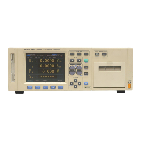
──────────────────────────────────────────────────── Chapter 2 Names and Functions of Parts 2.1 Panels and Key Operation START/STOP key OUTPUT keys PAGE keys FUNCTION keys HOLD key FUNCTION keys CURSOR keys LOCAL key Power switch RANGE keys Backlight off LED SHIFT key Front Panel ────────────────────────────────────────────────────... - Page 24 ──────────────────────────────────────────────────── FUNCTION MEAS Changes to the measurement value display screen STATUS Changes to the settings display screen Used for setting the file name of the floppy disk, and saving and recalling unit settings. PAGE In the MEAS and STATUS screens, used to switch display for the item in the second row from the top.
- Page 25 ──────────────────────────────────────────────────── Output connector (analog output, monitor output, D/A output, AC power inlet external control terminal) GP-IB connector 9603-01 Input terminal Voltage input terminal Serial number Clamp input terminal Current input terminal RS-232C connector Grounding terminal Rear Panel ──────────────────────────────────────────────────── 2.1 Panels and Key Operation...
-
Page 26: Names And Configuration Of Screen
──────────────────────────────────────────────────── 2.2 Names and Configuration of Screen 2.2.1 Screen Configuration The three basic screens are the MEAS (measurement) screen, the STATUS MEAS STATUS screen, and the FDD (floppy disk drive) screen. Pressing the key on the panel switches to the corresponding screen. This configuration is when all options are installed. -
Page 27: Meas Screen (Measurement Screen)
──────────────────────────────────────────────────── 2.2.2 MEAS Screen (Measurement Screen) This screen displays measurement results. The displays available depend on the options installed. Switch from one display to another using the PAGE key on the front panel. In this case the second row of cursor positions from the top of the screen shows the currently displayed page. - Page 28 ──────────────────────────────────────────────────── 3V3A/3P4W mode #204.tif ・ The subscript numbers on symbols indicate channels. For example, "U " NOTE indicates that the voltage measured on input unit channel 1 is displayed. The indication "U " indicates that the SUM value of the voltages measured on input unit channels 1, 2 and 3 is displayed.
- Page 29 ──────────────────────────────────────────────────── ② Selection screen [ SELECT ・Required items (except harmonics, flicker, and integration values) can be selected from all of the measurements being made and displayed. ・The screen format can be selected to show 4, 8, or 16 items. 4 items display screen 8 items display screen #207.tif #208.tif...
- Page 30 ──────────────────────────────────────────────────── ③ Efficiency screen [ EFFI By combining measurement values (active power, motor power), this calculates and displays the efficiency. #232-10.tif ④ External input screen [ EXT IN This is displayed when the optional 9603-01 EXTERNAL SIGNAL INPUT UNIT is installed. The motor power (Pm) is displayed only when the unit settings for channel A is torque, for channel B is number of rotating (rpm).
-
Page 31: Status Screen (Setting Screen)
──────────────────────────────────────────────────── 2.2.3 STATUS Screen (Setting Screen) This screen provides various settings. The screens correspond to the installed options. Switch from one display to another using the PAGE key on the front panel. In this case the second row of cursor positions from the top of the screen shows the currently displayed page. - Page 32 ──────────────────────────────────────────────────── ② Time control screen [ TIME This shows the settings for the response, averaging function, the interval time, timer time, and real-time control time. #CHANGE 233-4.tif ③ Frequency screen [ FREQ/OUTPUT This shows the settings for the output to FDD/printer, printing direction, saving screen color on FD, D/A output, frequency measurement function source, and frequency range of the unit.
- Page 33 ──────────────────────────────────────────────────── ⑤ Efficiency screen [ EFFI This sets the items to be substituted in the efficiency calculation expression. #233-7.tif (6) External input screen [ EXT UNIT This is displayed when the optional 9603-01 EXTERNAL SIGNAL INPUT UNIT is installed, and some settings are made for the 9603-01. #233-8.tif (7) Harmonic waveform screen This is displayed when the optional 9605-01 HARMONIC MEASURMENTS...
-
Page 34: Fdd Screen
──────────────────────────────────────────────────── 2.2.4 FDD Screen This supports file name setting of a floppy disk, and saving and loading of the unit settings. #234.tif ──────────────────────────────────────────────────── 2.2 Names and Configuration of Screen... -
Page 35: Indicators
──────────────────────────────────────────────────── 2.3 Indicators The following indicators are shown by panel key operation. #235.tif SHIFT Indicates when the SHIFT key is pressed. Pressing again goes off. Indicates key lock state (red), and remote state by GP-IB/RS- 232C (yellow). HOLD Indicates the displays are held. PEAK Indicates the peak hold function is active. -
Page 36: Peak Over Indication
──────────────────────────────────────────────────── 2.4 Peak Over Indication If the input voltage or current waveform peak exceeds six times the range value, a "PEAK" indication appears. These indications appear on the screen below the channel number, the voltage indication on the left and the current indication on the right, so that even a "PEAK"... -
Page 37: Chapter 3 Preparation For Measurement
──────────────────────────────────────────────────── Chapter 3 Preparation for Measurement 3.1 Notes on Use DANGER Always connect the powermeter input (including current sensor) to the secondary side of the breaker. On the secondary side of a breaker, even if the lines are shorted the breaker can trip and prevent an accident. - Page 38 ──────────────────────────────────────────────────── WARNING In order to prevent accidental electric shock and short circuits, shut off the power on the line to be measured before connecting DC voltage or current leads to the terminals. Be sure to connect the voltage input terminals, current input terminals correctly.
- Page 39 Before using the instrument the first time, verify that it operates normally to ensure that the no damage occurred during storage or shipping. If you find any damage, contact your dealer or Hioki representative. Peripheral Device Inspection Inspect the voltage measurement cables or connection cables.
-
Page 40: Basic Operating Procedure
──────────────────────────────────────────────────── 3.2 Basic Operating Procedure Check that the line to be measured is shut off, and 測定対象のラインが遮断されていることを確認、 check that this unit is powered off and the power および本器の電源が OFF され電源コードを抜いて cord disconnected from the outlet. あることを確認する Connect the power cord to the 3P-outlet. Turn the power on. -
Page 41: Powering On
HIOKI representative. Continued use of the unit could lead to fire or electric shock accidents. -
Page 42: Connecting The Direct Input Unit
──────────────────────────────────────────────────── 3.4 Connecting the Direct Input Unit The following diagrams show the connections in various modes when using the 9600 and 9601 AC/DC DIRECT INPUT UNIT AC DIRECT INPUT UNIT ■ Single-phase two wires (1P2W) i: 1 to 6 Source Source Load Load... - Page 43 ──────────────────────────────────────────────────── ■ Three-phase three wires (3P3W) i: 1, 3, 4, 5 Source Load Load Source Source Load ± ± ± ± ± ± ± ± ± ± ± ± Channel (i+1) Channel (i) Channel (i) Channel (i+1) Channel (i+1) Channel (i) Connecting the measured Using the current Using the voltage and current...
-
Page 44: Connecting The Clamp Input Unit
──────────────────────────────────────────────────── 3.5 Connecting the Clamp Input Unit The following diagrams show the connections in various modes when using the 9602 AC/DC CLAMP INPUT UNIT Single-phase two wires (1P2W) Single-phase three wires (1P3W) Source Load Source Load ± ± ± SENSOR SENSOR SENSOR Channel (i) -
Page 45: Measurement Losses
──────────────────────────────────────────────────── 3.6 Measurement Losses This unit is designed to have low measurement losses, and an extremely small effect on the power measurement values, but the following variant connection methods may be used to further reduce the effect of measurement losses. (1) When the voltage input is connected to the power supply side, the measurement includes losses from the input resistance of the current input terminals, but this yields the minimum measurement losses when the... -
Page 46: Error Messages
──────────────────────────────────────────────────── 3.7 Error Messages "Integration in progress (press START/STOP key to stop)." "Integration on standby (press SHIFT + START keys to reset)." "Reset not possible while integration in progress." "Time averaging is on." Operation "Stop time has passed, so real-time control is turned off." "Output in progress."... -
Page 47: System Reset
──────────────────────────────────────────────────── 3.8 System Reset To reset settings to the initial factory settings, there are following two methods. ・ When powering off SHIFT Turn the power on pressing the key until beep sounds. ・ On the STATUS screen 1. Press the STATUS key to display the SYSTEM... -
Page 48: Operations During Power Failure
──────────────────────────────────────────────────── 3.9 Operations During Power Failure ・ In the DC and AC+DC modes, after the power is restored, an offset CAUTION due to the circuit design may be output. In some cases the data may be invalid. ・ When the unit is powered off as a result of a power failure, continuing to input voltage and current may damage the unit. - Page 49 ──────────────────────────────────────────────────── Floppy disk drive ・ When automatic output is selected After the power is restored, a character string indicating that there was a power failure is output. (time of power failure and restoring) ・ Power failure during saving The data being saved is invalid. In the worst case there is a possibility of the file itself being corrupted.
- Page 50 ──────────────────────────────────────────────────── ──────────────────────────────────────────────────── 3.9 Operations During Power Failure...
-
Page 51: Chapter 4 Setting And Using The Basic Functions
──────────────────────────────────────────────────── Chapter 4 Setting and Using the Basic Functions 4.1 Setting the Wiring Mode (1P2W to 3P4W) This unit can have up to six input unit channels, allowing a single unit to measure anything from six 1P2W lines to two 3P4W systems. The connection mode of each channel also appears on the screen as shown below. - Page 52 ──────────────────────────────────────────────────── STATUS PAGE 1. Press the key, then use the UNIT UNIT keys to display the " " page. WIRING 2. Using the CURSOR keys, move the cursor to the WIRING " " item. 3. Press SELECT ) to switch to the connection setting screen.
- Page 53 ──────────────────────────────────────────────────── ・ It is only possible to select from the combinations shown in the connection NOTE setting screen. For combinations 1P3W and above, adjacent units must be of the same type. Channels ① 1P2W 1P2W 1P2W 1P2W 1P2W 1P2W ② 1P3W / 3P3W 1P2W 1P2W...
-
Page 54: Setting The Coupling Mode (Dc/Ac+Dc/Ac)
──────────────────────────────────────────────────── 4.2 Setting the Coupling Mode (DC/AC+DC/AC) 42-1.tif Coupling mode AC+DC ##42-2.tif -3 The coupling mode can be selected according to the measurement being performed. Switching using the panel keys CURSOR 1. Switch to display the channel for which you wish to change the setting. -
Page 55: Switching The Voltage Range And Current Range
──────────────────────────────────────────────────── 4.3 Switching the Voltage Range and Current Range When the voltage range and current range is displayed on the screen for each channel, it is also possible to change the ranges directly with the panel keys. This is also possible from the STATUS screen in the " UNIT "... - Page 56 ──────────────────────────────────────────────────── Switching the range on each channel screen. RANGE 1. Switch to display the channel for which you wish to change the setting. RANGE 2. Hold down the panel (+,-) key until the desired setting range is displayed. RANGE 3. To set auto ranging, hold down the panel 6 V ⇔...
-
Page 57: Effective Value (Rms) Or Mean Rectified Value (Mean) Selection
──────────────────────────────────────────────────── 4.4 Effective Value (RMS) or Mean Rectified Value (MEAN) Selection For voltage and current measurement, this unit has two different rectification circuits, which can be selected according to the signal being measured. 44-1.tif Switching for each channels on MEAS screen ・To switch the voltage, press the SHIFT key, and... -
Page 58: Setting The Scaling (Pt/Ct/Sc Ratios)
──────────────────────────────────────────────────── 4.5 Setting the Scaling (PT/CT/SC Ratios) This is used for setting the ratio (PT ratio or CT ratio) when using an external voltage transformer (PT) or current transformer (CT), and the scaling factor (SC ratio) for conversion of the active power to other physical units. - Page 59 ──────────────────────────────────────────────────── ・ For channel combinations of 1P3W and above, the PT ratio, CT ratio, or SC NOTE ratio must be the same for all channels in the combination. ・ When the channel identifies a CT6862, CT ratio of the channel is set to 2.5, as default.
-
Page 60: Setting The Low-Pass Filter (Lpf)
──────────────────────────────────────────────────── 4.6 Setting the Low-pass Filter (LPF) The input units of the 3194 are provided with a low-pass filter function for restricting the frequency characteristics. By using an appropriate filter selection it is possible to eliminate harmonics. Low-pass filter operation 47-1.tif... -
Page 61: Setting The Phase Polarity Discrimination Filter
──────────────────────────────────────────────────── 4.7 Setting the Phase Polarity Discrimination Filter For distorted waveforms such as inverter waveforms, the reactive power (Q), power factor ( λ ), and phase angle ( φ ) phase angle polarity may not be stable. In this case, by setting the phase polarity discrimination filter to "ON"... -
Page 62: Switching The Waveform Peak Value
──────────────────────────────────────────────────── 4.8 Switching the Waveform Peak Value The waveform peak value measurement can be set to voltage waveform (|Up(i)|) or current waveform (|Ip(i)|) UNIT STATUS PAGE 1. Press the key, then use the UNIT keys to display the " " page. CURSOR Peak 2. -
Page 63: Setting The Response (Fast/Mid/Slow)
──────────────────────────────────────────────────── 4.9 Setting the Response (FAST/MID/SLOW) There are three settings for the response time of analog outputs from this unit: FAST, MID, and SLOW. For measurement of a normal commercial power supply, the FAST setting is adequate, but is the frequency is low or there are sudden fluctuations, setting the response to MID or SLOW makes the display more stable. -
Page 64: Setting The Averaging
──────────────────────────────────────────────────── 4.10 Setting the Averaging (Time averaging/Moving averaging/Exponential averaging) This unit provides three averaging functions. The time average outputs the average over a fixed time interval, and the moving average and exponential average provide values which reflect the previous values. Averaging display AV-T Time averaging... - Page 65 ──────────────────────────────────────────────────── 1. Press the STATUS key, then use the PAGE TIME TIME keys to display the " " (time control) page. CURSOR 2. Using the keys, move the cursor to the " AVERAGING " item. ave time 3. Press AVE TIME 4.
- Page 66 ──────────────────────────────────────────────────── (2) Setting the Moving Average (AV-M) The moving average function displays a simple average calculated by summing the measurement values from the beginning of averaging, and dividing by the number of samples, until the specified number of samples. From that point on it discards the oldest data value as each new value is added, thus yielding a simple average over the most recent specified number of samples.
- Page 67 ──────────────────────────────────────────────────── (3) Setting the Exponential Average (AV-E) The exponential average provides a average of the previous values, but weighted toward the latest value. The effect of previous values thus diminishes exponentially. Zn: nth measured data + Zn (N-1) A : n-1 th display value Display value = ―――――――...
-
Page 68: Setting On The Meas Screen
──────────────────────────────────────────────────── 4.11 Setting on the MEAS Screen 4.11.1 Setting the Display Items (for 1 to 6 channels) For items on " DETAILS " for each channel screens, it is possible to select which measurement items to display. It is also possible to select whether to display the power factor ( λ ) or phase angle ( φ... -
Page 69: Setting The Select Screen
──────────────────────────────────────────────────── Setting items on "MAGNIFY" display 1. Select the magnification display to be set on channel screen, and press F5 (SELECT). The item list which can be selected is displayed. 2. Using the CURSOR keys, move the cursor to the desired display and select item from (↑) or (↓) to decide setting. -
Page 70: Setting On The System Screen
──────────────────────────────────────────────────── 4.12 Setting on the SYSTEM screen 4.12.1 Switching the Interface (GP-IB/RS-232C) This unit has GP-IB and RS-232C interfaces fitted as standard, and either one can be used as required. SYSTEM 1. Press the STATUS key, then use the PAGE SYSTEM keys to display the "... -
Page 71: Setting The Display Color
──────────────────────────────────────────────────── 4.12.2 Setting the Display Color You can select from four patterns for the screen display colors. STATUS PAGE 1. Press the key, then use the SYSTEM keys to display the " SYSTEM " page. CURSOR DISP COLOR 2. Using the keys, move the "... -
Page 72: Setting The Equation For Reactive Power (Q) And Apparent Power (S)
──────────────────────────────────────────────────── 4.12.4 Setting the Equation for Reactive Power (Q) and Apparent Power (S) This unit provides three different internal ways of computing the reactive power and apparent power. Select whichever is appropriate. See Section 19.3, "Calculations." SYSTEM STATUS PAGE 1. Press the key, then use the keys to display the "... -
Page 73: Setting The Beep Sound
──────────────────────────────────────────────────── 4.12.5 Setting the Beep Sound This unit sounds a "beep" each time a key is pressed. SYSTEM 1. Press the STATUS key, then use the PAGE SYSTEM keys to display the " " page. 2. Using the CURSOR keys, move the cursor to the "... -
Page 74: Setting The Display Language (English/Japanese)
──────────────────────────────────────────────────── 4.12.7 Setting the Display Language (English/Japanese) Display messages can be selected to appear in either Japanese or English. SYSTEM 1. Press the STATUS key, then use the PAGE SYSTEM keys to display the " " page. 2. Using the CURSOR keys, move the cursor to the "... -
Page 75: Degaussing
──────────────────────────────────────────────────── 4.13 Degaussing When a large DC current or large transient current is measured with the 9600 or an AC/DC type of current sensor for AC/DC DIRECT INPUT UNIT the 9602 , the internal DC-CT may become AC/DC CLAMP INPUT UNIT magnetized, thus outputting an offset even for a zero input. - Page 76 ──────────────────────────────────────────────────── ──────────────────────────────────────────────────── 4.13 Degaussing...
-
Page 77: Chapter 5 Frequency Measurement
──────────────────────────────────────────────────── Chapter 5 Frequency Measurement This unit has internal circuits for three frequency measurement channels (fa, fb, fc), and can thus measure a number of systems simultaneously. The frequency ranges can be combined with high-pass filters (HPF) and low- pass filters (LPF) ・... -
Page 78: Setting The Frequency Measurement Source (Fa)
──────────────────────────────────────────────────── 5.1 Setting the Frequency Measurement Source (fa) STATUS PAGE 1. Press the key, then use the key to FREQ/OUTPUT FREQ/OUTPUT display the " " page. CURSOR 2. Using the keys, move the cursor to the source item of "fa", and the window of settable source opens. -
Page 79: Setting The Frequency Range(Fa)
──────────────────────────────────────────────────── 5.2 Setting the Frequency Range(fa) CURSOR 1. Using the keys, move the cursor to the FREQ/OUTPUT frequency range item of "fa", and the window of frequency range opens. 2. Press (↑) and (↓) to display the desired range. 0.5 Hz to 50 Hz ⇔ 20 Hz to 500 Hz ⇔ 200 H to 5 kHz ⇔ FREQ RANGE 2 kHz to 50 kHz ⇔... - Page 80 ──────────────────────────────────────────────────── ──────────────────────────────────────────────────── 5.2 Setting the Frequency Range(fa)
-
Page 81: Chapter 6 Hold/Peak Hold Function
──────────────────────────────────────────────────── Chapter 6 Hold/Peak Hold Function 6.1 Hold Function HOLD Pressing the panel key freezes the display values of all items. By switching from one screen to another it is possible to compare different simultaneously captured values. HOLD Since internally the measurement continues, each time you press the key the values at that time are displayed. - Page 82 ──────────────────────────────────────────────────── ・ In the hold state, it is not possible to change settings. NOTE ・ In the auto-ranging, the range when the HOLD key is pressed is fixed. ・ In the hold state, external output values (for floppy disk or printer, through the GP-IB or RS-232C interface, or D/A output) are the values displayed on the screen.
-
Page 83: Peak Hold Function
──────────────────────────────────────────────────── 6.2 Peak Hold Function When the peak hold function is activated, only items exceeding the previous maximum value are updated continuously. For example, this can be used for measuring transient currents in an electric motor. 62.tif Peak hold state Display value Release peak holding Start peak holding... -
Page 84: Combination With Control Times
──────────────────────────────────────────────────── ・ If the display value is out of range, the indication "o.r." appears. In this case, NOTE first stop the peak hold function, then change the range. ・ The maximum value refers to the maximum absolute value. For example, after an input of "+50 W", an input of "-60 W"... -
Page 85: Chapter 7 Integration Function
──────────────────────────────────────────────────── Chapter 7 Integration Function 7.1 Overview For a 1P2W system in DC mode, the integration function in this unit can simultaneously integrate positive, negative, and total values for current (I) and active power (P) for all channels. There are six ways of controlling integration by the various time settings, as listed below. - Page 86 ──────────────────────────────────────────────────── ・ Data for each interval of the interval time setting is displayed on the screen NOTE in hold state. When the value is not held, it must be combined with the floppy disk drive or printer function to display. ・...
-
Page 87: Setting The Control Time
──────────────────────────────────────────────────── 7.2 Setting the Control Time Using the three time control functions provided by this unit, it is possible to control time averaging, the floppy disk drive, printer, and integration functions. ・ It is not possible to make separate settings for time averaging, floppy disk NOTE drive, printer, and integration functions. -
Page 88: Setting The Timer
──────────────────────────────────────────────────── ・ The interval setting is in steps of 10 seconds, to a maximum of 100 hours 00 NOTE minutes 00 seconds. ・ Even when operated without the timer or real-time control time set, the timer operates at 10,000 hours. For this reason, once 10,000 hours have elapsed, START/STOP pressing the key does not operate the unit. -
Page 89: Setting The Real Time Control
──────────────────────────────────────────────────── 7.2.3 Setting the Real Time Control Using the real-time control function, the internal real-time clock in the unit can be used to start and stop operation at specified times. This can also be used in combination with the interval time, to subdivide the time specified by real-time control. -
Page 90: Integration Screen
──────────────────────────────────────────────────── 7.3 Integration Screen On each channel screen, pressing the INTEGRATED ) function key moves to integration screen. Real-time control Integration operation indication indication STIME INTEG 73.tif Start time Stop time Integration elapsed time Integration item Load factor INTEG During integration, this display is shown in yellow. When integration end or during waiting integration, it is shown in blue. -
Page 91: Starting, Stopping, And Resetting The Integration
──────────────────────────────────────────────────── 7.4 Starting, Stopping, and Resetting the Integration There are three ways of starting, stopping, resetting integration, as shown below. These controls operate whether or not the integration screen is displayed. Panel key control Start START/STOP Starts integration by pressing the key. -
Page 92: Manual Integration (Controlled By Panel Keys)
──────────────────────────────────────────────────── 7.5 Manual Integration (Controlled by Panel Keys) Manual integration continues from the time that integration is started until any later point when it is stopped. 1. Select the channel and item to be Integration value integrated. Reset Stop Start 2. -
Page 93: Integration Using Time Settings (Controlled By Panel Keys)
──────────────────────────────────────────────────── 7.6 Integration Using Time Settings (Controlled by Panel Keys) By first setting the interval, timer, or real-time control time, and then pressing the START/STOP key, integration can be carried out for the specified time. ・ When the interval time is set, data for each interval of the interval time NOTE setting is not displayed on the screen. -
Page 94: Real-Time Control Integration
──────────────────────────────────────────────────── 7.6.2 Real-Time Control Integration Integration starts automatically at the start time of the real-time control time, and stops at the stop time. When the interval time is set, for each interval specified the total integration value at that point is written to the floppy disk or printer. Integration value Start time Reset... -
Page 95: Measuring The Load Factor
──────────────────────────────────────────────────── 7.7 Measuring the Load Factor When the timer or real-time control time setting is combined with the interval time, the load factor (LF) can be measured. The load factor result appears in the integration display. 1. Set the interval time, and timer time or Active power real time control time. -
Page 96: Zero Suppress Function
・ If the setting is 0.0% or 0.1%, figures not displayed as instantaneous values are also integrated. Note that, even when no inputs are being made, integration values may be displayed due to the offset status of the 3194 or for other reasons. -
Page 97: Chapter 8 Efficiency Measurement
──────────────────────────────────────────────────── Chapter 8 Efficiency Measurement 8.1 Overview This unit can calculate the efficiency from the measured values (active power, motor power). For example, the input/output efficiency of an inverter, input/output efficiency of a motor, and overall efficiency can be calculated simultaneously with a single unit. -
Page 98: Efficiency Screen
──────────────────────────────────────────────────── 8.2 Efficiency Screen In the MEAS screen, use the PAGE key to move the cursor to "EFFI" (efficiency) to display the efficiency screen. The calculation formula can be set in the "EFFI" display of the STATUS screen. 82-1.tif ──────────────────────────────────────────────────── 8.2 Efficiency Screen... -
Page 99: Setting The Calculation Formula
──────────────────────────────────────────────────── 8.3 Setting the Calculation Formula A maximum of three formulas can be set. 1. Press the STATUS key, then use the PAGE key to display the "EFFI" page. CURSOR 2. Next, use the keys to move the cursor to the denominator or numerator. -
Page 100: Example Measurement
8.4 Example Measurement The following is an example of measuring the efficiency. In either the 3P3W or 3V3A connection mode of the 3194, the active power NOTE (P) of a 3φ3W system is found by the two-power calculation method, and the efficiency calculation result is also the same. -
Page 101: Efficiency Measurement Of A Light Fitting (Two-Lamp)
──────────────────────────────────────────────────── 8.4.3 Efficiency Measurement of a Light Fitting (Two-Lamp) Input side (1φ2W) Output side (1φ2W) 50/60 Hz 50-150 kHz Inverter Lamp When channel 1 is the input and channel 2, 3 the output Input: 1P2W, AC mode / output: 1P2W, AC or AC+DC mode P 2+ P 3 η... -
Page 102: Efficiency Measurement Of An Inverter (3Φ3W) And Motor
──────────────────────────────────────────────────── 8.4.5 Efficiency Measurement of an Inverter (3φ3W) and Motor Output side (3φ3W) Basic wave: 0.5-100 Hz Input side (3φ3W) Carrier: 2-20 kHz 50/60 Hz Torque P 123 Inverter Motor meter P 456 Torque value Number (chA) of rotating (chB) When channel 1, 2, 3 are the input and channel 4, 5, 6 the output: Channel 1, 2, 3: input side, channel 4, 5, 6: output side Input: 3V3A, AC mode / output: 3V3A, AC or AC+DC mode... -
Page 103: Chapter 9 External Output/ External Control Terminals
──────────────────────────────────────────────────── Chapter 9 External Output/ External Control Terminals This unit is provided with analog, monitor, and D/A outputs as standard equipment, so that it can be used together with a recorder. Various controls are also possible, with terminals including external control of integration, external control of the screen hold function, floppy disk drive and printer control, control terminals for the 9605-01. -
Page 104: Connector Pin Arrangement
──────────────────────────────────────────────────── 9.1 Connector Pin Arrangement The pin arrangement of the terminals (ANALOG OUT D/A OUT, EXT.CONT) on the rear panel is shown below. U 1 analog output U 4 analog output I 1 analog output I 4 analog output P 1 analog output P 4 analog output U 1 monitor output U 4 monitor output... -
Page 105: Internal Circuit For Analog, Monitor, D/A Outputs
──────────────────────────────────────────────────── 9.2 Internal Circuit for Analog, Monitor, D/A Outputs The output rates are shown below. For the details, please see the specifications of the output unit. Output type Output rate Analog Output 5 Vf.s. (1 kV range: 3.333 Vf.s.) Monitor Output 1 Vf.s. -
Page 106: Internal Circuit For The External Control And Timing
──────────────────────────────────────────────────── 9.3 Internal Circuit for the External Control and Timing The external control signals can be 0/5 V logic signals or relay contact open/closed circuit signals. ・ To avoid damage to the unit, do not input voltage exceeding 5.5 V. CAUTION ・... -
Page 107: Fdd/Printer.start Terminal
──────────────────────────────────────────────────── 9.3.2 FDD/PRINTER.START Terminal This terminal controls starting of floppy disk and printer output. Using the printer: repeat 10 seconds or more Using the FDD: repeat 1 minute or more at least 300 ms (open-circuit) (short-circuit) ・ This signal is ignored when automatic output is activated. NOTE ・... - Page 108 ──────────────────────────────────────────────────── ──────────────────────────────────────────────────── 9.3 Internal Circuit for the External Control and Timing...
-
Page 109: Chapter 10 D/A Output
──────────────────────────────────────────────────── Chapter 10 D/A Output 10.1 Overview This unit is provided with eight channels of D/A output as standard equipment. The items displayed on the screen are output as DC voltages. In order to avoid electric shock or a short circuit, turn off the power WARNING meter and the power flowing through the line being measured before connecting or disconnecting a connector and an output connector. -
Page 110: Selecting Output Item
──────────────────────────────────────────────────── 10.2 Selecting Output Item 1. Press the STATUS key, then use the PAGE key to FREQ/OUTPUT display the " " page. D/A OUTPUT 2. Using the CURSOR keys, move the cursor to the " D/A OUTPUT " item. 3. Select desired item from the window by pressing ↑... -
Page 111: Output Rate
──────────────────────────────────────────────────── 10.3 Output Rate The D/A outputs are ±5 V DC corresponding to full scale, where the full scale values are as shown in the following table. Selecting items for output Full scale Voltage value, current value for each channel, Measurement range SUM value of voltage and current, 9603-01 EXTERNAL SIGNAL INPUT UNIT... - Page 112 ──────────────────────────────────────────────────── ──────────────────────────────────────────────────── 10.3 Output Rate...
-
Page 113: Chapter 11 Using The Floppy Disk Drive
3.5-inch (2HD) MS-DOS format 1.2 MB (NEC PC-9801) / 1.44 MB (IBM-PC/AT) Function ・ Saving measurement values ・ Saving the 3194 settings ・ Loading/resetting 3194 settings ・ Formatting a floppy disk (1.2 MB/1.44 MB) ・ Automatic saving using time settings ・... -
Page 114: Operation Procedure
See Section 11.8.5 See Section 11.8.1 See Section 11.8.2 The only file saved to floppy disk by the 3194 that can be reloaded is that NOTE created with [Save Device Settings]. With other measurement data and setting data files, it is only possible to check file names or delete files. See "11.11 Floppy Disk Data Output Format."... -
Page 115: Using The Floppy Disk
──────────────────────────────────────────────────── 11.3 Using the Floppy Disk Inserting a Floppy Disk Insert the floppy disk (with the printed label facing right) all of the way into the drive. If the floppy disk is inserted correctly, the Eject button will pop out. Ejecting a Floppy Disk Pressing the Eject button causes the floppy disk to pop out. -
Page 116: Formatting A Floppy Disk
──────────────────────────────────────────────────── 11.4 Formatting a Floppy Disk This function is used in order to format floppy disks. It is not necessary for the formatted floppy disk. The formatting process erases all data previously saved to that floppy CAUTION disk. Make sure that the floppy disk does not contain any essential data before formatting it. -
Page 117: Switching The Fdd/Printer
──────────────────────────────────────────────────── 11.5 Switching the FDD/Printer This unit has a built-in floppy disk drive (FDD) as standard equipment. A printer option is also available. Both of these can be used for data output as required. Output can also be controlled by the various time functions. FD indication Printer indication 412-1.tif... -
Page 118: Setting File Names For Saved Measurement Data
──────────────────────────────────────────────────── 11.6 Setting File Names for Saved Measurement Data The file name consists of up to eight characters. Use the following example as a guide to setting the file name. 116-1.tif CHANGE 1. Press the key to display the FDD screen. Meas. -
Page 119: Setting The Measurement Items For Saving
──────────────────────────────────────────────────── 11.7 Setting the Measurement Items for Saving 114-1.tif CHANGE, 114-2.tif FREQ/OUTPUT STATUS PAGE 1. Press the key and then use the key to FREQ/OUTPUT display the " " page. 2. Using the CURSOR keys, move the cursor to the OUTPUT ITEM OUTPUT ITEM "... -
Page 120: Saving The Data On Fdd
──────────────────────────────────────────────────── 11.8 Saving the Data on FDD 11.8.1 Automatic Saving Using Time Settings Automatic saving is achieved by combination with the interval, timer, or real-time control time settings. :Save Timer Timer Interval START Auto stop /STOP Auto stop START /STOP Interval Real time control START... -
Page 121: Manual Saving
──────────────────────────────────────────────────── 11.8.2 Manual Saving Pressing the SAVE/PRINT key can save the measurement data which is selected in Section 11.7. SAVE/PRINT During automatic output, the key is invalid. NOTE 11.8.3 Screen Hard Copy The screen display can be saved in bmp file. For settings of file name, see Section 11.6, "Setting File Names for Saved Measurement Data". -
Page 122: Saving And Loading Settings
──────────────────────────────────────────────────── 11.8.5 Saving and Loading Settings By saving the current settings of the unit and reloading them later, the current state can be restored. Saving the Settings 1. Insert the floppy disk into the unit. 2. Press the key to display the FDD screen. Configuration File CURSOR 3. -
Page 123: Information Which Can Be Saved
──────────────────────────────────────────────────── 11.9 Information Which Can Be Saved From the number of items being saved and the remaining capacity of a floppy disk, you can find out how many more save operations are possible. 1. Insert the floppy disk to be saved to the floppy drive. -
Page 124: Deleting And Confirming Files
──────────────────────────────────────────────────── 11.10 Deleting and Confirming Files This function is used to delete unnecessary files from a floppy disk. Confirmation of measurement data file name 1. Insert the floppy disk into the floppy disk drive. 2. Press the key to display the FDD screen. Files Files CURSOR... -
Page 125: Format For Data Output To Floppy Disk
──────────────────────────────────────────────────── 11.11 Format for Data Output to Floppy Disk Measurement data is saved in text format, and the data format is shown below. Files begin with a header section (all data that has been saved), followed by measurement value sections listed for each time period. A line feed is executed for the header section and for each measured value at each time. -
Page 126: Message And Error Displays
To clear the message, press any panel key. "Loading settings file" Appears when the main unit settings are loaded from a floppy disk. The 3194 is reset with the information from the settings file. "Formatting floppy disk" Appears when the process of formatting a floppy disk starts. -
Page 127: Chapter 12 Gp-Ib And Rs-232C Interface
・ It is not possible to use simultaneously both GP-IB and RS-232C interfaces. ・ The 3194 cannot communicate with a PC when the STATUS screen or the FDD screen is shown on the display of the 3194. Make sure that the MEAS screen is on. ────────────────────────────────────────────────────... -
Page 128: Specifications
12.2.1 GP-IB Interface Compliance standard: IEEE-488.1 1987 Reference standard: IEEE-488.2 1987 On the 3194, if the output queue becomes full, it is cleared and a query error NOTE is generated. This does not correspond to the clearing of the output queue and the outputting of a query error in the deadlock state as stipulated in IEEE 488.2. -
Page 129: Rs-232C Interface
(ASCII) is returned. (RS-232C: Set with the ANSWer command) Transmitted data from the 3194 000: no error nnn: error detected in item nnn of the received program code In the case of a query command, the transmission is appended after the response message. - Page 130 ──────────────────────────────────────────────────── To power meter RS-232C Cable To PC DOS/V PC Flow control: None, XON/XOFF Frame D-sub 9-pin Frame Female D-sub 25-pin Male Connection To PC To power meter DOS/V, PC-9801 PC Flow control: RTS/CTS, both Frame Frame Frame Frame D-sub 9-pin D-sub 25-pin D-sub 25-pin D-sub 25-pin...
- Page 131 ──────────────────────────────────────────────────── DOS/V PC To power meter To PC Flow control: None, XON/XOFF Frame Frame D-sub 9-pin D-sub 9-pin Female Female To power meter To PC DOS/V, PC-9801 PC Flow control: RTS/CTS, both Frame Frame D-sub 9-pin D-sub 9-pin Female Female Connecting example of Sanwa Supply's RS-232C Cables (reverse) Flow control None, XON/XOFF...
-
Page 132: Interface Outline
──────────────────────────────────────────────────── 12.3 Interface Outline 12.3.1 Messages Data received or sent by the interface is called a message. The following are the message types: Command messages Program messages Query messages Messages Response messages Execution confirmation messages (RS-232C only) Of these, program messages are those received by the unit from the controller, while response messages are those sent from the unit to the controller. -
Page 133: Command Syntax
──────────────────────────────────────────────────── 12.3.2 Command Syntax The names of commands for the 3194 are as far as possible mnemonic. Furthermore, all commands have a long form, and an abbreviated short form. In command references in this manual, the short form is written in upper case letters, and then this is continued in lower case letters so as to constitute the long form. -
Page 134: Message Terminators
(3) LF with EOI (GP-IB only), as message terminators. To terminate a response message, the 3194 always provides the appropriate EOI signal, and also sends a terminating character sequence. By the use of the "TRANsmit:TERMinator" command either of the following can be... -
Page 135: Data Formats
Further, if the accuracy of a numerical value exceeds the range with which the 3194 can deal, it is rounded off. (5 and above is rounded up; 4 and below is rounded down). ① NR1 format: integer data (+12, -23, 34) ②... -
Page 136: Abbreviation Of Compound Commands
──────────────────────────────────────────────────── For the integer values as a parameter of the following commands, the decimal fractions are rounded, but for the ":CURRent [channel]:RANGe" command for current range setting in range 0.2A and 0.5 A, the second decimal place is rounded. The real numbers as a parameter of the following commands are rounded to the fifth decimal place. -
Page 137: Output Queue
・When the unit is reset by a key press. ・When a query error is generated. The 3194 has an output queue of 2000 bytes capacity. If the response messages overflow this limit of 2000 bytes, a query error is generated, and the output queue is cleared. -
Page 138: Status Model
──────────────────────────────────────────────────── 12.3.11 Status Model In its implementation of the serial polling function using service requests, the 3194 employs the status model specified by IEEE 488.2. The term "event" refers to any phenomenon which generates a service request. Generation of service requests... -
Page 139: Status Byte Register
The status byte register is an 8-bit register whose contents are output from the 3194 to the controller, when serial polling is being performed. If even only one bit in the status byte register has changed from 0 to 1 (provided that it is a bit which has been set in the service request enable register as a bit which can be used), then the MSS bit is set to 1. ... -
Page 140: Event Registers
──────────────────────────────────────────────────── 12.3.13 Event Registers (1) Standard event status register (SESR) The standard event status register is an 8-bit register. If any bit in the standard event status register is set to 1 (after masking by the standard event status enable register), bit 5 (ESB) of the status byte register is set to 1. Status byte register (STB) bit 5 Standard event status register (SESR) - Page 141 1. ・Execution is impossible due to an abnormality inside the 3194. Query error. This bit is set to 1 when a query error is detected by the output queue control.
- Page 142 The event status registers are numbered 0 to 2, and are each 8-bit registers; they correspond to bits ESB0 to ESB3 of the status byte. Each bit has a particular 3194 event allocated to it. The constituent bits are masked by the corresponding event status enable register, then the summary (logical OR) is copied to one of bits 0 to 2 (ESB0- ESB2) of the status byte (STB).
- Page 143 ──────────────────────────────────────────────────── (4) Event status registers 0 (ESR0) This register is used principally to monitor start and stop processing events. The following commands are used for reading the event status register 0, and for setting the event status enable register 0 and for reading it. Reading event status register 0 *ESR0? Setting event status enable register 0...
- Page 144 ──────────────────────────────────────────────────── (5) Event status registers 1 (ESR1) This register is used to monitor the input units for out of range values. Bits 1 to 6 correspond to channels 1 to 6. The bits are summaries of the event status registers 11 to 16 (ESR11 to ESR16), which show the out-of-range information for each input unit.
- Page 145 ──────────────────────────────────────────────────── (6) Event status registers 2 (ESR2) This register monitors for out-of-range inputs to the 9605-01 HARMONIC MEASURMENTS UNIT. Its value is therefore all zeros unless the optional 9605-01 is installed. Bits 1 to 6 correspond to the harmonic analysis boards for channels 1 to 6. However, since a maximum of three harmonic analysis boards can be selected simultaneously, no more than three bits can ever be set.
- Page 146 ──────────────────────────────────────────────────── (7) Event status registers 11 to 26 (ESR11 to 26) These registers are event status registers indicating out-of-range inputs for input unit channels 1 to 6 and harmonic analysis board input channels 1 to 6. A summary of these registers is reflected in ESR1 and ESR2. The following commands are used for reading the event status register, and for setting the event status enable register and for reading it.
-
Page 147: Gp-Ib Commands
──────────────────────────────────────────────────── (8) Event status register F (ESRF) This register is an event status register indicating out-of-range inputs for frequency inputs. A summary of this register is reflected in bit OF of ESR1. The following commands are used for reading the event status register, and for setting the event status enable register and for reading it. -
Page 148: Command Reference
──────────────────────────────────────────────────── 12.4 Command Reference Common command: see Section 12.4.1 / Specific command : see Section 12.4.2 :Command Indicates functions of message reference Syntax : Indicates the command syntax. Function : Describes the function of the [ ] : (Header portion) command. -
Page 149: Standard Command
──────────────────────────────────────────────────── 12.4.1 Standard Command *CLS Clears the status byte register and the event registers. Function Syntax This instruction clears the event registers *CLS and the bits of the status byte register associated with that register (ESR, ESR0, ESR1, ESR2, ESR[ch], ESRF). Note This has no effect upon the output queue, the various enable registers, or bit 4 (the... - Page 150 ──────────────────────────────────────────────────── *ESE0 Sets the event status enable register 0. Function Syntax Sets the mask pattern of the event status *ESE0 <NR1> enable register 0 (ESER0) to a value (0 <NR1> = 0 to 255 to 255). Example Transmission *ESE0 34 bit 7 bit 6 bit 5 bit 4 bit 3 bit 2 bit 1 bit 0 Bits 5 and 1 of ESER0 are set to 34.
- Page 151 ──────────────────────────────────────────────────── *ESE1? Queries the standard event status enable register 1 (SESER1). Function Syntax The contents of the event status enable *ESE1? register 1 (ESER1) as set by the *ESE1 command are returned as a NR1 value (0 Response Same as *ESE1 to 255).
- Page 152 ──────────────────────────────────────────────────── *ESE [ channel no. ] Sets the standard event status enable registers 11 to 16, 21 to 26. Function Syntax Sets the mask pattern of the event status *ESE [11 - 16 / 21 - 26] <NR1> enable registers 11 to 16, 21 to 26 11 - 16: when using the input unit for (ESER11 to 16, 21 to 26) of specified channel 1 to 6...
- Page 153 ──────────────────────────────────────────────────── *ESEF? Queries the standard event status enable register F (SESERF). Function Syntax The contents of the event status enable *ESEF? register F (ESERF) as set by the *ESEF command are returned as a NR1 value (0 Response Same as *ESEF to 255).
- Page 154 ──────────────────────────────────────────────────── *ESR2? Queries event status register 2 (ESR2). Syntax Function The contents of ESR2 are returned as *ESR2? NR1 value (0 to 255). Response *ESR2 <NR1> Unless the contents of the channel for syntax <NR1> = 0 to 255 each bits are read, they are not cleared. Example (Header on) (Header off)
- Page 155 * IDN? query is produced. Transmission *IDN? ・ No header is affixed to the response Response HIOKI,3194,0,V1.00 message. ・ If any error occurs, no response message to this query is produced. Error Query error / If the response message is...
- Page 156 9279,9602,9279,9603‑ 01,9604,9605‑01 *RST Initializes the settings. Syntax Function ・ Resets the 3194 unit. *RST ・ The parameters which are reset are initialized by the reset function of the unit. The following settings are not affected by this command. The current path is initialized to the root, and headers are turned off.
- Page 157 ──────────────────────────────────────────────────── *SRE Sets the service request enable register (SRER). Syntax Function ・ Sets the SRER to a pattern is used to *SRE <NR1> mask the status byte register. <NR1> = 0 to 255 ・ SRER has the bit configuration shown Example below, and an NR1 value is set with this *SRE 34...
- Page 158 * TST? Requests execution of, and queries the result of, the self test. Syntax Function Causes the 3194 to perform the self test, * TST? and returns the result thereof as a numerical data value in NR1 format (0 to...
-
Page 159: Specific Commands
──────────────────────────────────────────────────── 12.4.2 Specific Commands :AOUT Sets the items of D/A output. Function Syntax AOUT <A, ...8 items> Sets the output items for channels 1 to 8 respectively of the D/A outputs <A> = Un, In, Pn, Qn, Sn, PFn, The D/A output item which is not DEGn, PIHn, MIHn, IHn, specified is set to U1. - Page 160 ──────────────────────────────────────────────────── :AVEraging:COEFficient Sets the averaging or attenuation coefficient. Syntax Function Sets the averaging or attenuation :AVEraging:COEFficient <NR1> coefficient for the sliding average or <NR1> = 8, 16, 32, 64 exponential average function. Example AVERAGING:COEFFICIENT? Transmission Response AVERAGING:COEFFICIENT 16 :AVEraging:COEFficient? Queries the averaging or attenuation coefficient. Syntax Function Sets the averaging or attenuation...
- Page 161 ──────────────────────────────────────────────────── :AVEraging? Queries the averaging. Syntax Function Queries the current setting for averaging :AVEraging? mode, averaging, or attenuation Response :AVERAGING:MODE <TIM/LIN/EXP/ coefficient. syntax OFF>:COEFFICIENT <8/16/32/64> Example Transmission :AVERAGING? Response :AVERAGING:MODE EXP:COEFFICIENT 8 When time averaging is selected. :AVERAGING:MODE TIM:COEFFICIENT 0 :BACKlight Enables or disables the LCD back light.
- Page 162 ──────────────────────────────────────────────────── :BACKlight:AUTO? Queries the automatic LCD backlight off time setting. Syntax Function Queries the current setting for auto-off :BACKlight:AUTO? time. Response :BACKLIGHT:AUTO <1-99> syntax Example Transmission :BACKLIGHT:AUTO? Response :BACKLIGHT:AUTO 10 :BEEPer Enables and disables beep sound. Syntax Function Enables or disables the beep sound. :BEEPer <ON/OFF>...
- Page 163 ──────────────────────────────────────────────────── :CALCulate [channel no.] :DENominator? Queries the items for the denominator in the specified efficiency formula. Syntax Function Queries the items set for the denominator :CALCulate [1/ 2/ 3] in the specified efficiency formula. :DENominator? 1:η1, 2:η2, 3:η3 Response :CALCULATE[1/2/3]:DENOMINATOR <A> syntax Example :CALCULATE1:DENOMINATOR?
- Page 164 Sets the real time (system clock). Syntax Function Sets the current setting (date and time, in :CLOCK <year,month,day,hour,min, yy-mm-dd-hh-mm-ss format) of the 3194 sec> system clock. year = 00 - 99 It is not possible to set time in RS-232C month = 1 - 12 mode.
- Page 165 ──────────────────────────────────────────────────── :COUPling [channel no.] Sets the coupling mode. Syntax Function Sets the coupling mode of the specified :COUPling [1 - 6] input unit. <AC/DC/ACDC> Note When using an input unit for which DC Example :COUPLING4 ACDC or AC+DC cannot be selected, specifying ー...
- Page 166 ──────────────────────────────────────────────────── :CURRent [channel no.] :MEAN Sets the rectifier type of current ranging. Syntax Function Sets the rectifier type (MEAN/RMS) of :CURRent [1 - 6]:MEAN <ON/OFF> current ranging for the specified input Example :CURRENT1:MEAN ON unit Sets the rectifier type of current Note If "DC"...
- Page 167 ──────────────────────────────────────────────────── :CURRent [channel no.] :RANGe? Queries the current ranging. Syntax Function Queries the current ranging of the :CURRent[1 - 6]:RANGe? specified input unit. Response :CURRENT[1 - 6]:RANGE <NR1> syntax Example :CURRENT1:RANGE? Transmission Response :CURRENT1:RANGE 50 :CURRent [channel no.]? Queries the current measurement. Syntax Function Queries the current settings for the...
- Page 168 ──────────────────────────────────────────────────── :DATAout:ITEM:EFFiciency? Queries the output item of the efficiency measurement. Syntax Function Queries the output item of the efficiency :DATAout:ITEM:EFFiciency? measurement to FDD or printer Response :DATAOUT:ITEM:EFFICIENCY <0-7> syntax Example :DATAOUT:ITEM:EFFICIENCY? Transmission Response :DATAOUT:ITEM:EFFICIENCY 1 :DATAout:ITEM:FREQuency Sets the output item for the frequency measurement to FDD or printer. Syntax Function Sets the output item for the frequency...
- Page 169 ──────────────────────────────────────────────────── :DATAout:ITEM:INTEGrate Sets the output item for integration. Syntax Function Sets the output items (10 items) for :DATAout:ITEM:INTEGrate integration (integration value, integration <NR1,..(10 items)> elapsed time) to FDD or printer. <NR1> = 0 - 63 The items are set as shown below by setting bits, to specify ten numerical Example :DATAOUT:ITEM:INTEGRATE...
- Page 170 ──────────────────────────────────────────────────── :DATAout:ITEM:LOADfactor Sets the output item for the load factor. Syntax Function Sets the output items for load factor to :DATAout:ITEM:LOADfactor <NR1 FDD or printer. 2 items> The items are set as shown below by <NR1> = 0 - 63 setting bits, to specify two numerical values.
- Page 171 ──────────────────────────────────────────────────── :DATAout:ITEM:NORMal Sets the output item for the normal measurement. Syntax Function Sets the output items (8 items) for :DATAout:ITEM:NORMal <NR1,.. measurement value for each channel (8 items)> (excluding sum value) <NR1> = 0 - 63 The items are set as shown below by setting bits, to specify eight numerical Example :DATAOUT:ITEM:NORMAL...
- Page 172 ──────────────────────────────────────────────────── :DATAout:ITEM:SUM Sets the output item for SUM value. Syntax Function Sets the output items (7 items) for SUM :DATAout:ITEM:SUM <NR1,.. value. (7 items)> The items are set as shown below by <NR1> = 0 - 63 setting bits, to specify seven numerical values.
- Page 173 Sets the output on a printer. Syntax Function Enables or disables outputting on a :DATAout:PRINter <ON/OFF> printer. Example :DATAOUT:PRINTER ON Errors Execution error / When the printer is not Sets the printer to on. installed in the 3194 ──────────────────────────────────────────────────── :DATAout:ITEM?
- Page 174 ──────────────────────────────────────────────────── :DATAout:PRINter? Queries the setting of the output on a printer. Syntax Function Queries the current setting for the :DATAout:PRINter? printing output. Response :DATAOUT:PRINTER <ON/OFF> syntax Example :DATAOUT:PRINTER? Transmission Response :DATAOUT:PRINTER ON :DATAout? Queries the all setting items on a FDD or printer. Syntax Function Queries the all setting items on a FDD or...
- Page 175 ──────────────────────────────────────────────────── :DISPlay:DETail [channel no.] Set items to be displayed on the "Detail display" screen of the channel screen. Syntax Function Set items to be displayed on the "Detail :DISPlay:DETail[1 - 6] <A>, .. display" screen of the specified channel screen, and select screen display. Example When measuring in 3V3A mode with Errors...
- Page 176 Makes a setting of the Integration screen for the specified channel. Syntax Function Makes a setting of the Integration screen :DISPlay:INTEGrate [1 - 6] for the specified channel. Example :DISPLAY:INTEGRATE1 Switch the display screen for the 3194 to the Detail screens for channel 1, 2, and 3. ──────────────────────────────────────────────────── :DISPlay:EFFiciency...
- Page 177 ──────────────────────────────────────────────────── :DISPlay:MAGnify [channel no.] Sets items to be displayed on the enlarged screen for the specified channel Syntax Function Sets items to be displayed on the :DISPlay:MAGnify[1 - 6] <A,..> enlarged screen for the specified channel Example If the data is not specified, the enlarged When measuring in 3V3A mode with screen for the specified channel is using the channels 1 to 3 of the input...
- Page 178 ──────────────────────────────────────────────────── :DISPlay:SELect [number of items] Sets items to be displayed on the Selection screen. Syntax Function Sets items to be displayed on the :DISPlay:SELect[4/8/16] <A,.(4, 8, Selection screen. If the data is not or 16 items)> specified, the specified selection screen is <A>: 4 items (when 4 item display) displayed.
- Page 179 ──────────────────────────────────────────────────── :DISPlay? Queries the screen displays. Syntax Function Queries the current screen displayed. :DISPlay? Response :DISPLAY <DETAIL [1-6]/ syntax INTEGRATE [1-6]/ MAGNIFY [1-6]/ SELECT [4/8/16] /EXTERNALIN/ EFFICIENCY> Example :DISPLAY? Transmission Response :DISPLAY INTEGRATE1 :FD:MANual Saves data on a floppy disk. Syntax Function Saves data on a floppy disk.
- Page 180 ──────────────────────────────────────────────────── :FREQuency [channel no.] :AUTO? Queries the auto ranging of the frequency measurement. Syntax Function Queries the auto ranging for the specified :FREQuency[A/B/C]:AUTO? channel of the frequency measurement. Response :FREQUENCY[A/B/C]:AUTO syntax <ON/OFF> Example :FREQUENCYFA:AUTO? Transmission Response :FREQUENCYFA:AUTO ON :FREQuency [channel no.] :RANGe s Sets the frequency range.
- Page 181 ──────────────────────────────────────────────────── :FREQuency [channel no.] :SOURce Sets the channel source of the frequency measurement. Syntax Function Sets the source of the frequency :FREQuency[A/B/C]:SOURce <A> measurement for specified channel. <A> = U1, U2, U3, U4, U5, U6, I1, I2, I3, I4 ,I5, I6 If the setting of external input for channel B is pulse measurement, the frequency...
- Page 182 :HEADer Enables and disables headers. Syntax Function Enables or disables headers of the :HEADer <ON/OFF> response message from the 3194. However, this excludes the reply Example ":HEADer ON" messages to some common commands. Sets the header for response to on.
- Page 183 ──────────────────────────────────────────────────── :INTEGrate:RESEt Resets the integration value. Syntax Function Resets the integration value. :INTEGrate:RESEt Note The integration values for all channels are Example ":INTEGRATE:RESET" simultaneously reset. In this case, for the Resets integration value for all channel during integration, an execution channels.
- Page 184 Function Queries the channels currently operating :INTEGrate? integration. When all channels controlled by the integration function are stopped, Example the 3194 sends a "0" reply to the PC. ":INTEGRATE?" Transmission Response ":INTEGRATE 1,2,3" :INTERval:CONTrol Enables and disables the interval time control.
- Page 185 ──────────────────────────────────────────────────── :INTERval? Queries the interval time control. Syntax Function Queries the current settings for interval :INTERval? time control. Response ":INTERVAL:CONTROL <ON/OFF>; syntax TIME <hour,min,sec> Example ":INTERVAL?" Transmission Response ":INTERVAL:CONTROL ON;TIME 000,10,00" :KEYLock Enables and disables key lock. Syntax Function ・ Enables and disables key lock. :KEYLock <ON/OFF>...
- Page 186 ──────────────────────────────────────────────────── :LANGuage? Queries the language to be displayed. Syntax Function Queries the current setting of display :LANGuase? language. Response :LANGUAGE <ENGlish/JAPanese> syntax Example ":LANGUAGE?" Transmission Response ":LANGUAGE ENGLISH" :LPF[channel no.] Sets the low-pass filter (LPF). Syntax Function Sets the cut-off frequency (fc) of the low- :LPF[1 - 6] <NR1>...
- Page 187 ──────────────────────────────────────────────────── :MATH? Queries the calculation. Syntax Function Queries the current setting of the :MATH? calculation method for apparent power and reactive power. Response :MATH <1/2/3> syntax Example ":MATH?" Transmission Response ":MATH 1" :MEASure:ITEM Specify the default items to be transferred. Syntax Function Specify the default items to be transferred...
- Page 188 ──────────────────────────────────────────────────── :MEASure:ITEM:EFFiciency? Queries the output item of the efficiency measurement. Syntax Function Queries the output item of the efficiency :MEASure:ITEM:EFFiciency? measurement specified by the Response ":MEASURE:ITEM:EFFICIENCY ":MEASure:ITEM:EFFiciency <NR1>" syntax <NR1>" Example ":MEASURE:ITEM:EFFICIENCY?" Transmission Response ":MEASURE:ITEM:EFFICIENCY 1" :MEASure:ITEM:FREQuency Sets the output item for the frequency measurement. Syntax Function Specify the default items to be transferred...
- Page 189 ──────────────────────────────────────────────────── :MEASure:ITEM:INTEGrate Sets the output item for integration. Syntax Function Sets the default items (only integration :MEASure:ITEM:INTEGrate value and integration elapsed time) to be <NR1,...(10 items)> transferred in the response message to the <NR1> = 0 - 63 ":MEASure?" query in the default mode. The items are set as shown below by Example ":MEASURE:ITEM:INTEGRATE...
- Page 190 ──────────────────────────────────────────────────── :MEASure:ITEM:LOADfactor Sets the output item for the load factor. Syntax Function Sets the default items (only load factor :MEASure:ITEM:LOADfactor LF) to be transferred in the response <NR1, (2 items)> message to the ":MEASure?" query in the <NR1> = 0 - 63 default mode.
- Page 191 ──────────────────────────────────────────────────── :MEASure:ITEM:NORMal Sets the output item for the normal measurement. Syntax Function Sets the default items (only measurement :MEASure:ITEM:NORMal <NR1, value for each channels) to be transferred (8 items)> in the response message to the <NR1> = 0 - 63 ":MEASure?"...
- Page 192 ──────────────────────────────────────────────────── :MEASure:ITEM:SUM Sets the output item for the SUM value. Syntax Function Sets the default items (only SUM value) :MEASure:ITEM:SUM <NR1, (7 to be transferred in the response message items)> to the ":MEASure?" query in the default <NR1> = 0 - 63. mode.
- Page 193 ──────────────────────────────────────────────────── :MEASure:ITEM? Queries the default items. Syntax Function Queries the all default items specified by :MEASure:ITEM? the ":MEASure:ITEM <NR1>" Response ":MEASURE:ITEM:NORMAL <0-63 syntax (8 items)>;SUM <0-63 (7 items)>; INTEGRATE <0-63 (10 items)>; FREQUENCY <0-7>;LOADFACTOR <0-64 (2 items)>;EFFICIENCY <0-7>; EXTERNALIN <0-7>" Example Transmission ":MEASURE:ITEM?"...
- Page 194 ──────────────────────────────────────────────────── :MEASure? Queries the specified data. Syntax ① Default mode Function ① Default mode If no parameters are specified in the data :MEASure? section, then this mode is used. Default ② Data specification mode item data specified by the :MEASure? <A (up to 70 items)> ":MEASure:ITEM"...
- Page 195 ──────────────────────────────────────────────────── :MODE Sets the wiring mode. Syntax Function Sets the wiring mode. :MODE <1P2W/1P3W/3P3W/ 3V3A/3P4W> Note The only possible wiring configuration is that shown below. Example When the same type of input unit is Combinations 1P3W and above require installed in all six channels, then when all of the input units to be the same type.
- Page 196 ──────────────────────────────────────────────────── :PHF [channel no.] Switches on or off the phase polarity discrimination filter for the specified channel. Syntax Function Switches on or off the polarity detection :PHF[1 - 6] <ON/OFF> stabilization filter for the specified input unit. Example ":PHF1 ON" Enables the polarity detection Note ・...
- Page 197 :RESPonse Sets the response speed. Syntax Function Sets the response speed. :RESPonse <FAST/MID/SLOW> Note This applies to the whole 3194 unit. Example ":RESPONSE FAST" Separate specifications for different input Sets the response speed to FAST. units are not possible. :RESPonse? Queries the response speed.
- Page 198 ──────────────────────────────────────────────────── :RTC:COUNt? Queries the sampling count. Syntax Function Queries the current setting of sampling :RTC:COUNt? count. Response :RTC:COUNT <0-10000> syntax Example ":RTC:COUNT?" Transmission Response ":RTC:COUNT 4" :RS232c:ANSWer (Command for the RS-232C interface) Sets whether or not the execution confirmation message Syntax Function ・...
- Page 199 ──────────────────────────────────────────────────── :RS232c:ERRor? (Queries for the RS-232C interface) Queries whether or not the RS-232C communications error information are enabled. Syntax Function ・ Returns the RS-232C communications RS232c:ERRor? error information as a numerical data value in NR1 format (0 to 7) and then Response (Headers: ON) clears.
- Page 200 ──────────────────────────────────────────────────── :RS232c:HANDshake? (Queries for the RS-232C interface) Queries the setting for the RS-232C communications handshake. Syntax Function The value of the communications :RS232c:HANDshake? handshake is returned as character data (X, HARD or OFF). Response Headers: ON syntax :RS232C:HANDSHAKE <X/ HARD/ Errors ・...
- Page 201 ──────────────────────────────────────────────────── :SCALe [channel no.] :CONTrol? Queries the setting of scaling function of PT, CT, SC ratios. Syntax Function Queries the current setting of scaling :SCALe[1 - 6]:CONTrol? function for specified input unit. Response :SCALE:[1-6]:CONTROL <ON/OFF>, syntax <ON/OFF>,<ON/OFF> Example ":SCALE1:CONTROL?" Transmission Response ":SCALE1:CONTROL ON,ON,OFF"...
- Page 202 ──────────────────────────────────────────────────── :SCALe [channel no.] :PT Sets the PT ratio. Syntax Function Sets the PT ratio for the specified input :SCALe[1 - 6]:PT <NR2> unit. <NR2> = 0.0001 to 10000 Notes ・ Specifying a value which cannot be Example ":SCALE1:PT 1000" selected because of the number of input units installed results in an execution Sets the PT ratio for channel 1 to...
- Page 203 ──────────────────────────────────────────────────── :SCALe [channel no.] :SC? Queries the SC ratio. Syntax Function Queries the current setting of SC ratio for :SCALe:SC[1 - 6]? the specified input unit. Response :SCALE:SC[1-6] <NR2> syntax Example ":SCALE:SC1?" Transmission Response ":SCALE:SC1 1000" :SCALe [channel no.] ? Queries the settings of the scaling function.
- Page 204 ──────────────────────────────────────────────────── :STOP Stops all of the various timer settings at the beginning of a cycle. Syntax Function All of the various timer settings stop at :STOP the beginning of a cycle. The operation is the same as pressing the START/STOP Example ":STOP"...
- Page 205 ──────────────────────────────────────────────────── :STIMe:STARTtime? Queries the start time of the real time control. Syntax Function Queries the current setting of the start :STIMe:STARTtime? time for the real time control. Response ":STIME:STARTTIME syntax <year,month,day,hour,min> Example ":STIME:STARTTIME?" Transmission Response ":STIME:STARTTIME 97,12,15,16,50" :STIMe:STOPTime Sets the stop time of the real time control. Syntax Function Sets the stop time for the real time...
- Page 206 ──────────────────────────────────────────────────── :TIMER:CONTrol Enables and disables the timer control. Syntax Function Enables and disables the timer control. :TIMER:CONTrol <ON/OFF> Note To start timer time control execute the Example ":TIMER:CONTROL ON" ":STARt" command, and to stop execute Enables the timer control. the ":STOP" command. :TIMER:CONTrol? Queries the timer control.
- Page 207 ──────────────────────────────────────────────────── :TIMER? Queries the timer control. Syntax Function Queries the current settings for timer :TIMER? control. Response ":TIMER:CONTROL <ON/OFF>; syntax TIME <hour,min>" Example ":TIMER?" Transmission Response ":TIMER:CONTROL ON;TIME 00000,10" :TRANsmit:COLumn Select the numerical data format. Syntax Function Sets the numerical data format of TRANsmit:COLumn <NR1>...
- Page 208 ──────────────────────────────────────────────────── :TRANsmit:SEParator Sets the message unit separator for response messages. Syntax Function ・ When the header is off, the data separator TRANsmit:SEParator <NR1> is set as follows: <NR1> = 0, 1 If <NR1> = 0, the separator is set to semicolon ";".
- Page 209 Syntax Function ・ For the talker, the terminator (delimiter) :TRANsmit:TERMinator <NR1> of the response message sent by the 3194 <NR1> = 0, 1 (0: LF, 1: CR+LF) is switched. (When the 3194 is the In either case, an LF and EOI are listener, either can always be used.)
- Page 210 ──────────────────────────────────────────────────── :VOLTage [channel no.] :AUTO? Queries whether or not voltage auto ranging is enabled. Syntax Function Queries the current setting of the voltage :VOLTage[1 - 6]:AUTO? auto ranging for specified input unit. Response :VOLTAGE[1-6]:AUTO <ON/OFF> syntax Example ":VOLTAGE1:AUTO?" Transmission Response ":VOLTAGE1:AUTO ON"...
- Page 211 ──────────────────────────────────────────────────── :VOLTage [channel no.] :RANGe Sets the voltage range. Syntax Function Sets the voltage range for the specified :VOLTage[1 - 6]:RANGe <NR1> input unit. <NR1> = Error Execution error/ If the setting data is (9600) 6, 15, 30, 60, 150, 300, 600, other than listed on the left.
- Page 212 ──────────────────────────────────────────────────── :WAVEpeak [channel no.] Selects whether the waveform peak measurement function applies to the voltage or current. Syntax Function Selects whether the waveform peak :WAVEpeak[1 - 6] <U/I> measurement function applies to the voltage or current. Example ":WAVEPEAK1 U" Sets the waveform peak measurement Notes ・...
-
Page 213: Command Summary
──────────────────────────────────────────────────── 12.5 Command Summary 12.5.1 Standard Commands [ch]: channel no. / [No.]: number of items Data format Command Explanation Page (number of data items) * CLS Clears STB and ESR. * ESE NR1 numerical data (1) Sets bitmask for ESR. * ESE? Queries bitmask for ESR. -
Page 214: Commands Specific To The 3194
──────────────────────────────────────────────────── 12.5.2 Commands Specific to the 3194 [ch]: channel no. / [No.]: number of items Data format Command Explanation Page ( ): number of data items :AOUT Character data Sets D/A output items. :AOUT? Queries D/A output items. :AVEraging:COEFficient NR1 numerical data Sets the averaging or attenuation value. - Page 215 ──────────────────────────────────────────────────── [ch]: channel no. / [No.]: number of items Data format Command Explanation Page ( ): number of data items :DATAout:ITEM:ALLClear Clears default output settings. :DATAout:ITEM:EFFiciency NR1 numerical data (1) Sets the output data of efficiency measurement value. :DATAout:ITEM:EFFiciency? Queries the output data of efficiency measurement value.
- Page 216 ──────────────────────────────────────────────────── [ch]: channel no. / [No.]: number of items Data format Command Explanation Page ( ): number of data :DISPlay:SELect[No.] Character data (16) Sets items to be displayed on the Selection screen. :DISPlay:SELect[No.]? Queries items to be displayed on the Selection screen.
- Page 217 ──────────────────────────────────────────────────── [ch]: channel no. / [No.]: number of items Data format Command Explanation Page ( ): number of data items :MEASure:ITEM Character data (35) Specify the default items to be transferred. :MEASure:ITEM? Queries the data output items. :MEASure:ITEM:ALLClear Clears all default items to be transferred. :MEASure:ITEM:EFFiciency NR1 numerical data (1) Sets the output data of efficiency...
- Page 218 ──────────────────────────────────────────────────── [ch]: channel no. / [No.]: number of items Data format Command Explanation Page ( ): number of data items :RS232c:ERRor? Queries whether or not the RS-232C communications error information are enabled. :RS232c:HANDshake Character data (1) Sets the RS-232C communications handshake :RS232c:HANDshake? Queries the setting for the RS-232C...
- Page 219 ──────────────────────────────────────────────────── [ch]: channel no. / [No.]: number of items Command Data format Explanation Page ( ): number of data items :VOLTage[ch]:AUTO ON/OFF Enables and disables the voltage auto ranging. :VOLTage[ch]:AUTO? Queries whether or not voltage auto ranging is enabled. :VOLTage[ch]:MEAN ON/OFF Sets the rectifier type of the voltage range.
-
Page 220: Valid Command According To Condition (Standard Command)
──────────────────────────────────────────────────── 12.5.3 Valid Command According to Condition (Standard Command) Integration reset Integration start Integration stop Condition HOLD HOLD HOLD PEAK PEAK PEAK Command * CLS * ESE * ESE? * ESE0 * ESE0? * ESE1 * ESE1? * ESE2 * ESE2? * ESE[ch] * ESE[ch]? * ESEF... -
Page 221: Valid Command According To Condition (Specific Command)
──────────────────────────────────────────────────── 12.5.4 Valid Command According to Condition (Specific Command) [ch]: channel no. / [No.]: number of items Integration reset Integration start Integration stop Condition HOLD HOLD HOLD Command PEAK PEAK PEAK :AOUT - - - - - - - - :AOUT? :AVEraging:COEFficient -... - Page 222 ──────────────────────────────────────────────────── [ch]: channel no. / [No.]: number of items Integration reset Integration start Integration stop Condition HOLD HOLD HOLD Command PEAK PEAK PEAK :DATAout:ITEM:ALLClear - - - - - - - - :DATAout:ITEM:EFFiciency - - - - - - - -...
- Page 223 ──────────────────────────────────────────────────── [ch]: channel no. / [No.]: number of items Integration reset Integration start Integration stop Condition HOLD HOLD HOLD Command PEAK PEAK PEAK :FD:MANual - - - :FREQuency[ch]:AUTO - - - - - - - - :FREQuency[ch]:AUTO? :FREQuency[ch]:RANGe - - -...
- Page 224 ──────────────────────────────────────────────────── [ch]: channel no. / [No.]: number of items Integration reset Integration start Integration stop Condition HOLD HOLD HOLD Command PEAK PEAK PEAK :MEASure:ITEM - - - - - - - - :MEASure:ITEM:ALLClear - - - - - - - -...
- Page 225 ──────────────────────────────────────────────────── [ch]: channel no. / [No.]: number of items Integration reset Integration start Integration stop Condition HOLD HOLD HOLD Command PEAK PEAK PEAK :SCALe[ch]:CONTrol - - - - - - - - :SCALe[ch]:CONTrol? :SCALe[ch]:CT - - - - - - -...
-
Page 226: Execution Time Of Gp-Ib Interface Command
However for commands with parameter data, the time is that for the case determined by the data format specified by the data item, and for queries the time is that with headers enabled. ・ With the exception of the following, all 3194 commands and queries are of NOTE the overlap type. -
Page 227: Initialization
──────────────────────────────────────────────────── 12.5.6 Initialization The following table shows which items are initialized and which not, under various conditions. Initialize method *RST Device *CLS Power on Item command clear command GP-IB device address - - - - RS-232C setting - - - -... -
Page 228: Specific Command Tree
──────────────────────────────────────────────────── 12.5.7 Specific Command Tree :AOUT :AOUT? :COEFficient :AVEraging :COEFficient? :AVEraging? :MODE :MODE? :AUTO :BACKlight :AUTO? :BACKlight? :BEEPer :BEEPer? :DENominator :CALCulate[ch] :DENominator? :CALCulate[ch]? :NUMerator :NUMerator? :CLOCK :CLOCK? :COUPling[ch] :COUPling[ch]? :CURRent[ch] :AUTO :CURRent[ch]? :AUTO? :MEAN :MEAN? :RANGe :RANGe? :ITEM :DATAout :ALLClear :ITEM? :DATAout? :EFFiciency... - Page 229 ──────────────────────────────────────────────────── :MANual :AUTO :FREQuency[ch] :AUTO? :FREQuency[ch]? :RANGe :RANGe? :SOURce :SOURce? :HEADer :HEADer? :HOLD :HOLD? :INTEGrate :RESEt :INTEGrate? :STARt :STOP :CONTrol :INTERval :CONTrol? :INTERval? :TIME :TIME? :KEYLock :KEYLock? :LANGuage :LANGuage? :LPF[ch] :LPF[ch]? :MATH :MATH? :ALLClear :MEASure :ITEM :EFFiciency :MEASure? :ITEM? :EFFiciency? :MODE :FREQuency :MODE?
- Page 230 ──────────────────────────────────────────────────── :RESPonse :RESPonse? :RTC :COUNt :COUNt? :ANSWer :RS232c :ANSWer? :RS232c? :ERRor? :HANDshake :HANDshake? :CONTrol :SCALe[ch] :CONTrol? :SCALe[ch]? :CT? :PT? :STARt :SC? :STOP :CONTrol :STIMe :CONTrol? :STIMe? :STARTtime :STARTtime? :STOPTime :STOPTime? :CONTrol :TIMER :CONTrol? :TIMER? :TIME :TIME? :COLumn :TRANsmit :COLumn? :TRANsmit? :SEParator :SEParator? :TERMinator...
-
Page 231: Sample Programs
20 Initialize the interface 20 CLEAR 701 20 インタフェース初期化 30 OUTPUT 701;"*RST" 30 3194を初期化する 30 Initialize the 3194 40 OUTPUT 701;":TRAN:TERM 1" 40 ターミネータをCR+LFにする 40 Set delimiter to "CR+LF" 50 OUTPUT 701;":VOLT1:RANG 150;AUTO OFF;MEAN OFF" 50 電圧レンジ150V 50 Set ranges to 150 V 60 OUTPUT 701;":CURR1:RANG 10;AUTO OFF;MEAN OFF" ... -
Page 232: Rs-232C
20 OPEN "COM1:9600,N,8,1,LF" FOR RANDOM AS #1 20 RS‑232C回線オープン 30 Initialize the 3194 30 PRINT #1,"*RST" 30 3194を初期化する 40 Set delimiter to "CR+LF" 40 PRINT #1,":TRAN:TERM 1" 40 ターミネータをCR+LFにする... -
Page 233: Device Compliance Statement
:MEAS? 1 to 70 ③ Queries producing responses as syntax checking is performed: On the 3194, all queries produce responses when syntax checking is performed. ④ Whether any queries produce responses when read: There are no queries which produce response messages at the instant they are read in by the controller. - Page 234 * LRN?, * RCL?, and * SAV are not used. The * RST command returns the 3194 to its initial state. (Refer to "Standard Commands", and "Initialization"). (20) Scope of the self-testing executed as a result of the * TST? query This is detailed in "Standard Commands".
-
Page 235: Notes On Interface
Are all the devices powered on? Is the STATUS screen or the FDD screen on? Press the LOCAL key on the front panel of the 3194 to release After transmission on the GP-IB the remote state. bus, the keys on the 3194 freeze Has a LLO (Local Lock-Out) command been transmitted? up and have no effect. -
Page 236: Rs-232C Troubleshooting
Is RS-232C (band rate, data length, parity, stop bits) set the same? After transmission on the RS- Press the LOCAL key on the front panel of the 3194 to release 232C, the keys on the 3194 the remote state. freeze up and have no effect. -
Page 237: Chapter 13 Using The Printer (Option)
Always use the HIOKI specified product. ・ Color printing is not possible. ・ The printing is not affected by the English/Japanese setting for the display. -
Page 238: Specifications
──────────────────────────────────────────────────── 13.2 Specifications Printing method Thermosensitive line dot-matrix Printing digits 33 digits/line Printing speed 8 lines/s Printing width 72 mm Recording paper Black thermosensitive recording paper Width: 74 mm×10 m Core inner diameter: 12 mm Maximum outer diameter: 33 mm End of paper: Red marking for 0.5 m Functions Measurement item printing... -
Page 239: Operating Procedure
──────────────────────────────────────────────────── 13.3 Operating Procedure Insert the recording See Section 13.4 paper into the printer STATUS FREQ/OUTPUT OUTPUT DEVICE See Section 13.5 PRINTER FD&PRINT STATUS Display the screen FREQ/OUTPUT to be printed OUTPUT ITEM See Section 13.5 See Section 7.2 Set the control times SHIFT START SAVE... -
Page 240: Loading Recording Paper
──────────────────────────────────────────────────── 13.4 Loading Recording Paper 1. Open the printer cover. 2. Insert the attachment into the roll of recoding paper. 3. Put down the head up/down lever. 4. Insert the end of the recording paper and pull it out to the other side. -
Page 241: Switching The Fdd/Printer
──────────────────────────────────────────────────── 13.5 Switching the FDD/Printer This unit has a built-in floppy disk drive (FDD) as standard equipment. A printer option is also available. Both of these can be used for data output as required. Output can also be controlled by the various time functions. FD indication Printer indication 412-1.tif... -
Page 242: Setting The Measurement Items To Print
──────────────────────────────────────────────────── 13.6 Setting the Measurement Items to Print STATUS PAGE 1. Press the key and then use the FREQ/OUTPUT FREQ/OUTPUT to display the " " page. CURSOR 2. Using the keys, move the cursor to the OUTPUT ITEM " " item. OUTPUT ITEM SELECT 3. -
Page 243: Printing Out
──────────────────────────────────────────────────── 13.7 Printing Out Whatever method the printout is started by, after the printout no paper feed occurs. If, therefore, outputting to the paper cutter, it is necessary to feed the SHIFT paper. After the printout, hold down the key and press the SAVE/PRINT key to feed the last line of printing to the paper cutter. - Page 244 ──────────────────────────────────────────────────── ① Timer : Print START/STOP Printing occurs when key is pressed Timer and then stops automatically. ② Interval time START Auto stop /STOP START/STOP Printing occurs when the key is pressed, for each interval elapsed, and then stops Interval START/STOP when the key is pressed or 10000...
-
Page 245: Screen Hard Copy
10A or 20A will be printed out for the channel by the help printing mode. 13.7.5 External Control Printing Using the external control connector on the rear panel of the 3194, a printout can be started by external control. For timing and other details, see Section 9.3.2, "FDD/PRINTER. START Terminal."... -
Page 246: Setting The Printing Direction
──────────────────────────────────────────────────── 13.8 Setting the Printing Direction You can select the printing direction. STATUS PAGE 1. Press the key and then use the FREQ/OUTPUT to display the " " page. CURSOR 2. Using the keys, move the cursor to the " PRINT DIRECTION "... -
Page 247: Error And Overflow Displays
──────────────────────────────────────────────────── 13.9 Error and Overflow Displays Error displays When an error occurs, is displayed in red. Error display Meaning "No paper loaded" Attempt to print when no paper loaded. "Printer head up" Printer head is up. "Printer: head is up." Outside temperature range of specification. - Page 248 ──────────────────────────────────────────────────── ──────────────────────────────────────────────────── 13.9 Error and Overflow Displays...
-
Page 249: Chapter 14 9600 Ac/Dc Direct Input Unit (Option)
Measurement which is attempted with the wiring connected incorrectly may cause damage to the unit or a short- circuit. When the power of the 3194 is turned off, do not apply voltage or CAUTION current to the voltage input terminal or current input terminal. Doing so may damage the unit. -
Page 250: Notes On Use
──────────────────────────────────────────────────── 14.2 Notes on Use ・The 9600 is a factory-fitted option. It therefore requires the 3194 unit for calibration or repair. ・For accurate measurement, allow one hour for warming up before use. ・It may not be possible to obtain accurate measurements close to a transformer or conductor carrying a large high-frequency current, or close to any device such as a radio transmitter generating a strong magnetic field. -
Page 251: Specifications (Using With The 3194)
──────────────────────────────────────────────────── 14.3 Specifications (using with the 3194) U ) I ) P ) Voltage ( Current ( Active power ( Input type Resistor voltage divider Isolated input, using DC- ―――― + isolation amplifier, CT method for isolated input Measurement type... - Page 252 Between U/I input terminals and case, between U/I input terminals and power plug Insulation resistance When using with the 3194 100 MΩ or more at 500 V DC Between U/I input terminals and case, between U/I input terminals and power plug ──────────────────────────────────────────────────── 14.3 Specifications (using with the 3194)
- Page 253 ──────────────────────────────────────────────────── Input voltage Frequency (Hz) 9600 Voltage Accuracy Assurance Range Input current Frequency (Hz) 9600 Current Accuracy Assurance Range ──────────────────────────────────────────────────── 14.3 Specifications (using with the 3194)
-
Page 254: Internal Block Diagram
Attenuation Isolation RMS/DC Range amplifier circuit ± Switch control MEAN/DC RMS/DC DC-CT Range ± MEAN/DC Multiplication 3194 Auto-zero Peak hold f measurement Waveform U / I shaping LEAD/LAG Polarity decision OVER Over detect OVER DMAG (0 Adj) 14.4.1 RMS Value (root-mean-square value) Using a dedicated RMS-DC conversion IC, processing is carried out equivalent to the theoretical expression for effective value. - Page 255 ──────────────────────────────────────────────────── 14.4.2 MEAN Value (MEAN rectification effective value for display) For MEAN values, the input signal waveform is converted to a DC voltage by an absolute value detecting circuit and a smoothing circuit Since this is an analog process, all signals within the frequency range of the specification are converted precisely.
- Page 256 ──────────────────────────────────────────────────── 14.4.4 Waveform Peak Value Measurement Circuit The waveform peak value is obtained by passing the signal waveform after absolute value detection through an analog peak hold circuit. U waveform Absolute value U / I switching Reset Absolute value I waveform 14.4.5 Crest Factor The crest factor indicated the magnitude of the dynamic range of the tester, and is given by the following expression:...
- Page 257 Measurement which is attempted with the wiring connected incorrectly may cause damage to the unit or a short- circuit. When the power of the 3194 is turned off, do not apply voltage or CAUTION current to the voltage input terminal or current input terminal. Doing so may damage the unit.
- Page 258 ──────────────────────────────────────────────────── 15.2 Notes on Use ・The 9601 is a factory-fitted option. It therefore requires the 3194 unit for calibration or repair. ・For accurate measurement, allow one hour for warming up before use. ・It may not be possible to obtain accurate measurements close to a transformer or conductor carrying a large high-frequency current, or close to any device such as a radio transmitter generating a strong magnetic field.
- Page 259 ──────────────────────────────────────────────────── 15.3 Specifications (using with the 3194) U ) I ) P ) Voltage ( Current ( Active power ( Input type Resistor voltage divider Isolated input, using CT ―――― + isolation amplifier, method for isolated input Measurement type Analog processing:...
- Page 260 Between U/I input terminals and case, between U/I input terminals and power plug Insulation resistance 100 MΩ or more at 500 V DC (When using with the 3194) Between U/I input terminals and case, between U/I input terminals and power plug ────────────────────────────────────────────────────...
- Page 261 ──────────────────────────────────────────────────── Input voltage Frequency (Hz) 9601 Voltage Accuracy Assurance Range Input current Frequency (Hz) 9601 Current Accuracy Assurance Range ──────────────────────────────────────────────────── 15.3 Specifications (using with the 3194)
- Page 262 Attenuation Isolation RMS/DC Range amplifier circuit ± Switch control MEAN/DC RMS/DC Range ± MEAN/DC Multiplication 3194 Auto-zero Peak hold f measurement Waveform U / I shaping LEAD/LAG Polarity decision OVER Over detect OVER ──────────────────────────────────────────────────── 15.4 Internal Block Diagram...
- Page 263 Measurement which is attempted with the wiring connected incorrectly may cause damage to the unit or a short- circuit. ・ When the power of the 3194 is turned off, do not apply voltage or CAUTION current to the voltage input terminal or external current sensor. Doing so may damage the unit.
- Page 264 ──────────────────────────────────────────────────── 16.2 Notes on Use ・The 9602 is a factory-fitted option. It therefore requires the 3194 unit for calibration or repair. ・For accurate measurement, allow one hour for warming up before use. ・It may not be possible to obtain accurate measurements close to a transformer or conductor carrying a large high-frequency current, or close to any device such as a radio transmitter generating a strong magnetic field.
- Page 265 ──────────────────────────────────────────────────── 16.3 Specifications (using with the 3194) U ) I ) P ) Voltage ( Current ( Active power ( Input type Resistor voltage divider Isolated input, using ―――― + isolation amplifier, current sensor type for isolated input Measurement type...
- Page 266 U / I ) 1Vrms f.s. (When input DC, sine Display accuracy (100 kHz or less): ±0.2%f.s wave, range full scale) (100 kHz to 200 kHz): ±3dB Maximum rated voltage 600 V to earth ──────────────────────────────────────────────────── 16.3 Specifications (using with the 3194)
- Page 267 U input terminals and clamp input terminal plug, between Insulation resistance 100 MΩ or more at 500 V DC (When using with the 3194) U input terminals and clamp input terminal, between U input Between U input terminals and power plug...
- Page 268 Isolation RMS/DC Range amplifier circuit ± Switch control MEAN/DC Sensor RMS/DC Buffer Range ± MEAN/DC Multiplication 3194 Auto-zero Peak hold f measurement Waveform U / I shaping LEAD/LAG Polarity decision OVER Over detect OVER DMAG (0 Adj) For details on RMS value, MEAN value, active power, waveform peak value measurement circuit, peakover detect circuit, see Chapter 14.
- Page 269 HIOKI cannot bear any responsibility for damage that occurs during shipment. Fuses The 3194 uses a switched power supply and is equipped with an internal fuse. This fuse cannot be replaced externally. ────────────────────────────────────────────────────...
- Page 270 ──────────────────────────────────────────────────── 17.2 Disposing of the Unit This unit uses a lithium battery for memory backup. Remove the lithium battery before disposing of the power meter, and follow the prescribed method when disposing of the unit. WARNING To avoid electric shock when removing the battery, disconnect the input cable, clamp on sensor and power cord.
- Page 271 ──────────────────────────────────────────────────── Chapter 18 Rack Mounting 18.1 Rack Mounting Fittings A-A Section Symmetry at Fittings for EIA (19-inch) standard rack mounting A-A Section B-B Section Fittings for EIA (19-inch) standard rack mounting on the right side ──────────────────────────────────────────────────── 18.1 Rack Mounting Fittings...
- Page 272 ──────────────────────────────────────────────────── A-A Section B-B Section Fittings for EIA (19-inch) standard rack mounting on the left side A-A Section Material: Fittings for JIS standard rack mounting ──────────────────────────────────────────────────── 18.1 Rack Mounting Fittings...
- Page 273 ──────────────────────────────────────────────────── 18.2 Installation Procedures When installing the unit into the rack, or when installing handle or WARNING stand removed, use the specified screws. Using screws that are longer than specified will cause internal short circuits, resulting in destruction of the equipment and a possible electrocution hazard. To maintain the measurement accuracy of the unit, bear the following NOTE cooling measures in mind:...
- Page 274 ──────────────────────────────────────────────────── For JIS standard For EIA standard External Dimensions ──────────────────────────────────────────────────── 18.2 Installation Procedures...
- Page 275 ──────────────────────────────────────────────────── Chapter 19 Specifications (unit only) When including options, refer to the separate specifications of the CAUTION options. 19.1 General Specifications Location for use Indoors, altitude up to 2000 m (6562 feet) Storage temperature and humidity C to 50 C (-50° F to 122° F) 80% RH or less (no range condensation) Operating temperature and...
- Page 276 ──────────────────────────────────────────────────── Measurement items When using the optional units; 9600, 9601, 9602: Voltage (U), current (I), active power (P), apparent power (S), reactive power (Q), power factor ( λ ), phase angle ( φ ), frequency (f), current integration (Ih), power integration (WP), efficiency ( η ), load factor (LF) When using the optional unit;...
- Page 277 ──────────────────────────────────────────────────── Accessories Instruction manual (For the 3194 main unit and the 9605-01) Power cord Connector Applicable standards EN61010 Safety Using with the 9600 and 9601: Voltage/current inputs; 600 - 1000 V Pollution level 2, measurement category II (expected transient overvoltage: 6000 V)
- Page 278 ──────────────────────────────────────────────────── 19.2 Function Specifications When using the 9605-01, see the specifications of the 9605-01. U, I, P ) (when using the 9600, 9601, 9602) 1. Voltage, current, active power measurements ( Measurement type Analog computation within the input unit of U, I, and P for each channel For 1P3W and above, the SUM value of U, I, and P is computed digitally in the main unit.
- Page 279 Pulses input to channel B of the 9603-01 (when the pulse setting is selected) are counted by the 3194 frequency measurement function (channel fc) and displayed. Accuracy Same as accuracy of frequency measurement function of the 3194 Display range Same as display range of frequency measurement function of the 3194...
- Page 280 ──────────────────────────────────────────────────── P m measurement) ③ Motor power ( Measurement type Digital computation from the measured voltage or pulse signal. In the case that the 9603-01 channel A unit is torque and channel B unit is rotation count/rate. Accuracy ±1dgt. with respect to the value computed from the measurement values Display range 0.1 to 130% of setting voltage range when both channel A and B...
- Page 281 ──────────────────────────────────────────────────── Ih , power integration WP ) 8. Integration measurement (current integration Measurement type Digital calculation from the measured value of I, P Accuracy ±1dgt. with respect to the value computed from the measurement value for each channel (I, P) Number of measurement 64 times/s Measurement item...
- Page 282 ──────────────────────────────────────────────────── η 1/ η 2/ η 3) 10. Efficiency calculation function ( Calculation item Active power (P) for each input units or motor power (Pm) when using with the 9603-01 Calculation Calculation accuracy For computed values of measurement values with items replaced, maximum ±7 dgt.
- Page 283 ──────────────────────────────────────────────────── 14. Other functions Coupling mode switching DC/ AC+DC/ AC DC or AC+DC mode cannot be used when using the 9601 or when using the 9602 with the AC current sensor Rectifier type switching RMS/ MEAN In DC coupling mode, switching is not possible Response switching FAST/MID/SLOW LPF switching...
- Page 284 ──────────────────────────────────────────────────── 19.3 Calculations 1. Voltage ( U ), Current ( I ), Active power ( P ) U ) I ) P ) Voltage ( Current ( Active power ( 1P2W U I P U I (i+1) (i+1) U 1P3W I...
- Page 285 ──────────────────────────────────────────────────── 3. Apparent power ( S ), Reactive power ( Q ) Type 1 Apparent power ( Reactive power ( 1P2W 1P3W (i)(i+1) (i+1) (i+1) (i+1) (i+1) (i)(i+1) (i+1) (i+1) = ─ ( 3P3W (i)(i+1) (i+1) (i)(i+1) (i+1) (i+1) (i+1) (i+1) (i+1) 3V3A...
- Page 286 ──────────────────────────────────────────────────── ・ The suffixes (i), (i+1), and (i+2) on the items indicate the channel numbers being used. For example, when measuring with channels 1 and 2 in 3P3W mode, the voltages on the channels are indicated as "U1" and "U2", and the SUM value as "U12." ・...
- Page 287 ──────────────────────────────────────────────────── 4. Power range 4.1 1P2W 9600, 9601 DIRECT INPUT UNIT (9601 does not have 6 V, 15 V, 30 V ranges) unit: W I (A) 200.0 m 500.00 m 1.0000 2.0000 5.0000 10.000 20.000 50.000 U (V) 6.0000 1.2000 3.0000 6.0000 12.000...
- Page 288 ──────────────────────────────────────────────────── 9602 + 200 A sensor (9278, CT6863, 9271, 9272, 9272-10: 200 A ranges) unit: W I (A) 5.000 10.000 20.000 50.000 100.00 200.00 U(V) 6.0000 30.000 60.000 120.00 300.00 600.00 1.2000 k 15.000 75.000 150.00 300.00 750.00 1.5000 k 3.0000 k 30.000 150.00...
- Page 289 ──────────────────────────────────────────────────── 19.4 Internal Block Diagram of the 3194 The internal construction of the 3194 is shown below. The broken lines indicate options. When the optional input units (9600, 9601, and 9602) are used, the voltage (U), current (I), and active power (P) are converted to DC voltages by analog computation in the input unit, and the waveform peak value is detected by an analog peak hold function.
- Page 290 ──────────────────────────────────────────────────── ──────────────────────────────────────────────────── 19.4 Internal Block Diagram of the 3194...
- Page 291 APPENDIX 1 ──────────────────────────────────────────────────── Appendix 3P3W wiring Diagram for the example using the option 9605 Voltage Load ① ② ① Voltage is measured between lines and current is measured with phase, so U2 is phased 60°from U1. When the load is purely resistive, I1 lags U1 by 30°, and I2 leads U2 by 30°.
- Page 292 APPENDIX 2 ──────────────────────────────────────────────────── 3V3A wiring Diagram for the example using the option 9605 Voltage Load ① ② ① Based on 3P3W wiring, the three channels of voltage and current are summed. The figures above show the state when the load is purely resistive. ②...
- Page 293 INDEX 1 ──────────────────────────────────────────────────────── Index - A - - D - iv,35,233,237,241,247 7,85-87,91-93,141,264 Active power D/A output 7,85-87 Analog outputs Data formats iv,54,171,260 Apparent power Data length 36,61,147,163,193 57,156,197 Auto range Degaussing Device compliance statement - B - 35,50,51,157 Display item 5,53,143,196 Backlight - E -...
- Page 294 INDEX 2 ──────────────────────────────────────────────────────── - G - - O - 7,52,109,264 GP-IB Output queue Ground terminal Output rate - H - - P - 24,40,184 Hardware handshake 115,164 73,177,238 Headers Peak hold 178,227 Help Peak over 63,89,164 43,178 Hold Phase polarity discrimination filter (phF) Power failure - I - Power switch...
- Page 295 INDEX 3 ──────────────────────────────────────────────────────── - T - 46,142 Time averaging 70,188,265 Timer - V - Voltage input terminal 37,191 Voltage range - W - vii,22 Warming up 44,238 Waveform peak value 33,177 Wiring mode - X - 111-113 XON/XOFF ─────────────────────────────────────────────────────── Index...
- Page 296 INDEX 4 ──────────────────────────────────────────────────────── ─────────────────────────────────────────────────────── Index...
- Page 297 ──────────────────────────────────────────────────── ────────────────────────────────────────────────────...
- Page 298 ──────────────────────────────────────────────────── ────────────────────────────────────────────────────...
- Page 300 HIOKI USA CORPORATION 6 Corporate Drive, Cranbury, NJ 08512, USA TEL +1-609-409-9109 FAX +1-609-409-9108 E-mail: hioki@hiokiusa.com URL http://www.hiokiusa.com HIOKI (Shanghai) Sales & Trading Co., Ltd. 1608-1610, Shanghai Times Square Office 93 Huaihai Zhong Road Shanghai, P.R.China POSTCODE: 200021 TEL +86-21-63910090 / 63910092 FAX +86-21-63910360 E-mail: info@hioki.com.cn URL http://www.hioki.cn...
Need help?
Do you have a question about the 3194 and is the answer not in the manual?
Questions and answers