KROHNE OPTIWAVE 7300 C Handbook
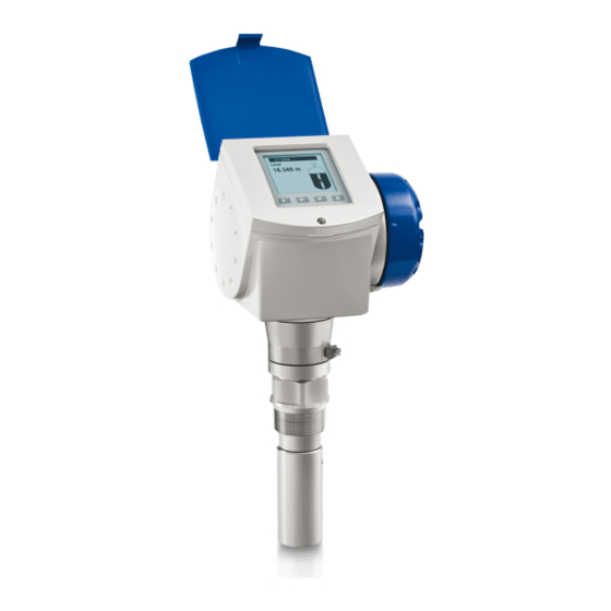
Non-contact radar (fmcw) level meter for liquids
Hide thumbs
Also See for OPTIWAVE 7300 C:
- Handbook (200 pages) ,
- Quick start manual (36 pages) ,
- Supplementary instructions manual (28 pages)
Table of Contents
Advertisement
Quick Links
Advertisement
Table of Contents

Related Manuals for KROHNE OPTIWAVE 7300 C


Summary of Contents for KROHNE OPTIWAVE 7300 C
- Page 1 OPTIWAVE 7300 C OPTIWAVE 7300 C OPTIWAVE 7300 C Handbook Handbook Handbook Handbook Non-contact Radar (FMCW) Level Meter for liquids for distance, level, volume and mass measurement of liquids © KROHNE 04/2011 - 4000172404 - HB OPTIWAVE 7300 R06 en...
- Page 2 All rights reserved. It is prohibited to reproduce this documentation, or any part thereof, without the prior written authorisation of KROHNE Messtechnik GmbH. Subject to change without notice. Copyright 2011 by KROHNE Messtechnik GmbH - Ludwig-Krohne-Str. 5 - 47058 Duisburg (Germany) www.krohne.com 04/2011 - 4000172404 - HB OPTIWAVE 7300 R06 en...
-
Page 3: Table Of Contents
CONTENTS OPTIWAVE 7300 C 1 Safety instructions 1.1 Intended use ........................7 1.2 Certification ........................7 1.3 Electromagnetic compatibility ..................7 1.4 Radio approvals ........................ 8 1.4.1 European Union (EU)....................... 8 1.4.2 U.S.A. and Canada........................9 1.5 Safety instructions from the manufacturer ..............9 1.5.1 Copyright and data protection .................... - Page 4 CONTENTS OPTIWAVE 7300 C 4 Electrical connections 4.1 Safety instructions......................39 4.2 Electrical installation: outputs 1 and 2 ................39 4.2.1 Non-Ex devices ........................40 4.2.2 Devices for hazardous locations................... 40 4.2.3 PROFIBUS PA........................41 4.2.4 FOUNDATION Fieldbus ......................41 4.3 Protection category ......................
- Page 5 CONTENTS OPTIWAVE 7300 C 7 Service 7.1 Periodic maintenance..................... 87 7.2 How to clean the top surface of the device ..............87 7.3 How to clean horn antennas under process conditions ..........87 7.4 How to replace device components ................87 7.4.1 Service warranty ........................
- Page 6 CONTENTS OPTIWAVE 7300 C 10 Appendix 10.1 Order form ........................129 10.1.1 Device data ........................129 10.1.2 Rating data ........................130 10.1.3 Contact data ........................130 10.2 Glossary ........................131 11 Notes www.krohne.com 04/2011 - 4000172404 - HB OPTIWAVE 7300 R06 en...
-
Page 7: Safety Instructions
SAFETY INSTRUCTIONS OPTIWAVE 7300 C 1.1 Intended use This radar level transmitter measures distance, level, mass, volume and reflectivity of liquids, pastes and slurries. It can be installed on tanks, reactors and open channels. 1.2 Certification DANGER! For devices used in hazardous areas, additional safety notes apply; please refer to the Ex documentation. -
Page 8: Radio Approvals
SAFETY INSTRUCTIONS OPTIWAVE 7300 C 1.4 Radio approvals 1.4.1 European Union (EU) LEGAL NOTICE! This level transmitter is intended for installation in closed metallic tanks. It meets the requirements of the R & TTE (Radio Equipment and Telecommunications Terminal Equipment) Directive 1999/05/EC for use in the member countries of the EU. -
Page 9: And Canada
SAFETY INSTRUCTIONS OPTIWAVE 7300 C 1.4.2 U.S.A. and Canada LEGAL NOTICE! This device complies with Part 15 of the FCC Rules and with RSS-210 of Industry Canada. Operation is subject to the following two conditions: 1. This device may not cause harmful interference, and 2. -
Page 10: Disclaimer
SAFETY INSTRUCTIONS OPTIWAVE 7300 C 1.5.2 Disclaimer The manufacturer will not be liable for any damage of any kind by using its product, including, but not limited to direct, indirect or incidental and consequential damages. This disclaimer does not apply in case the manufacturer has acted on purpose or with gross negligence. -
Page 11: Product Liability And Warranty
SAFETY INSTRUCTIONS OPTIWAVE 7300 C 1.5.3 Product liability and warranty The operator shall bear responsibility for the suitability of the device for the specific purpose. The manufacturer accepts no liability for the consequences of misuse by the operator. Improper installation and operation of the devices (systems) will cause the warranty to be void. The respective "Standard Terms and Conditions"... -
Page 12: Warnings And Symbols Used
SAFETY INSTRUCTIONS OPTIWAVE 7300 C 1.5.5 Warnings and symbols used Safety warnings are indicated by the following symbols. DANGER! This information refers to the immediate danger when working with electricity. DANGER! This warning refers to the immediate danger of burns caused by heat or hot surfaces. -
Page 13: Device Description
DEVICE DESCRIPTION OPTIWAVE 7300 C 2.1 Scope of delivery INFORMATION! Check the packing list to check if you received completely all that you ordered. Scope of delivery - horn antenna Figure 2-1: Scope of delivery - horn antenna 1 Signal converter and antenna in compact version... - Page 14 DEVICE DESCRIPTION OPTIWAVE 7300 C Scope of delivery - Drop antenna Figure 2-2: Scope of delivery - Drop antenna 1 Signal converter and antenna in compact version 2 Antenna extensions (option) and o-ring for each antenna extension 3 Quick Start...
-
Page 15: Device Description
DEVICE DESCRIPTION OPTIWAVE 7300 C 2.2 Device description This device is a 24 GHz FMCW-radar level transmitter. It is a non-contact technology and is 2- wire loop-powered. It is designed to measure the distance, level, mass, volume and reflectivity of liquids, pastes and slurries. -
Page 16: Visual Check
DEVICE DESCRIPTION OPTIWAVE 7300 C 2.3 Visual Check WARNING! If the display screen glass is broken, do not touch. INFORMATION! Inspect the cartons carefully for damage or signs of rough handling. Report damage to the carrier and to the local office of the manufacturer. -
Page 17: Nameplates
DEVICE DESCRIPTION OPTIWAVE 7300 C 2.4 Nameplates INFORMATION! Look at the device nameplate to ensure that the device is delivered according to your order. Check for the correct supply voltage printed on the nameplate. 2.4.1 Non-Ex nameplate Figure 2-6: Non-Ex nameplate 1 Indicator arrow to cable entry / cable entry size. -
Page 18: Installation
INSTALLATION OPTIWAVE 7300 C 3.1 Notes on installation INFORMATION! Inspect the cartons carefully for damage or signs of rough handling. Report damage to the carrier and to the local office of the manufacturer. INFORMATION! Check the packing list to check if you received completely all that you ordered. -
Page 19: Transport
INSTALLATION OPTIWAVE 7300 C 3.3 Transport Figure 3-2: How to lift the device 1 Remove the converter before you lift the device with a hoist. WARNING! Lift the device carefully to prevent damage to the antenna. 3.4 Pre-installation requirements INFORMATION! Obey the precautions that follow to make sure that the device is correctly installed. -
Page 20: How To Prepare The Tank Before You Install The Device
INSTALLATION OPTIWAVE 7300 C 3.5 How to prepare the tank before you install the device CAUTION! To avoid measuring errors and device malfunction, obey these precautions. 3.5.1 Pressure and temperature ranges Figure 3-3: Pressure and temperature ranges 1 Flange temperature ®... -
Page 21: Theoretical Data For Nozzle Position
INSTALLATION OPTIWAVE 7300 C 3.5.2 Theoretical data for nozzle position CAUTION! Follow these recommendations to make sure that the device measures correctly. Figure 3-4: Recommended nozzle position for liquids, pastes and slurries 1 Nozzles for DN40 or DN50 Horn antennas, or DN50 Hygienic antenna... -
Page 22: Theoretical Data For Hygienic Applications
INSTALLATION OPTIWAVE 7300 C Figure 3-5: Product inlets 1 The device is in the correct position. 2 The device is too near to the product inlet. Figure 3-6: More than 1 FMCW radar level meter can be operated in a tank More than 1 FMCW radar level meter can be operated in a tank. -
Page 23: Installation Recommendations For Liquids
INSTALLATION OPTIWAVE 7300 C 3.6 Installation recommendations for liquids 3.6.1 General requirements INFORMATION! We recommend that you configure the device when the tank is empty. Figure 3-8: General Installation recommendations 1 Do not tilt the device more than 2° How to use the... -
Page 24: Standpipes
INSTALLATION OPTIWAVE 7300 C 3.6.2 Standpipes Use a standpipe if: • There is highly conductive foam in the tank. • The liquid is very turbulent or agitated. • There are too many other objects in the tank. • The device is measuring a liquid (petro-chemicals) in a tank with a floating roof. - Page 25 INSTALLATION OPTIWAVE 7300 C Stilling wells - general notes Installation in tanks containing one liquid and foam • Drill a pressure equalization hole in the stilling well above the maximum level. • Deburr the hole. Installation in tanks containing one liquid or more without foam •...
- Page 26 INSTALLATION OPTIWAVE 7300 C Figure 3-11: Horizontal cylindrical tanks 1 The device is installed without a stilling well. There are multiple reflections. Refer to the CAUTION! that follows. 2 The device is installed in a stilling well and measures correctly.
-
Page 27: How To Install The Device On The Tank
INSTALLATION OPTIWAVE 7300 C Installation next to tanks containing more than one liquid • The top process connection of the bypass chamber must be above the maximum level of liquid. • The bottom process connection of the bypass chamber must be below the lowest measured level of liquid. - Page 28 INSTALLATION OPTIWAVE 7300 C Requirements for flange connections Figure 3-13: Flange connection If the antenna is smaller than the process connection: • Make sure the flange on the nozzle is level. • Make sure that you use the applicable gasket for the flange dimensions and the process.
-
Page 29: How To Install A Device With A Threaded Connection
INSTALLATION OPTIWAVE 7300 C WARNING! If you attach the antenna in a closed space, make sure that there is a good airflow in the area. Make sure that a person not in the tank can always hear you. If the antenna is larger than the process connection: •... - Page 30 INSTALLATION OPTIWAVE 7300 C Figure 3-16: How to attach the device if the antenna is larger than the process connection Equipment needed: • 3 mm Allen wrench (not supplied) WARNING! If you attach the antenna in a closed space, make sure that there is a good airflow in the area.
-
Page 31: How To Install A Device With A Hygienic Connection
INSTALLATION OPTIWAVE 7300 C If the process connection of the device is smaller than the process connection on the tank: • Make sure the tank connection is level. • Use a plate with a slot or a different applicable procedure to adapt the device to the tank. - Page 32 INSTALLATION OPTIWAVE 7300 C ® Tri-Clamp Equipment needed: • Device • Gasket (not supplied) • Band clamp (not supplied) ® Figure 3-18: Tri-Clamp connection 1 Tank socket 2 Band clamp ® How to attach a device with a Tri-Clamp connection •...
- Page 33 INSTALLATION OPTIWAVE 7300 C Figure 3-19: DIN 11851 connection 1 Tank socket 2 Nut for DIN 11851 connection How to attach a device with a DIN 11851 connection • Make sure the tank connection is level. • Make sure that you use the applicable gasket for the connection dimensions and the process.
-
Page 34: How To Attach Antenna Extensions
INSTALLATION OPTIWAVE 7300 C How to attach a device with a SMS connection • Make sure the tank connection is level. • Make sure that you use the applicable gasket for the connection dimensions and the process. • Align the gasket correctly. - Page 35 INSTALLATION OPTIWAVE 7300 C Drop antenna - antenna extensions Figure 3-22: Drop antenna - how to attach antenna extensions INFORMATION! Drop antenna: Drop antenna: Antenna extensions can only be attached below flanges without the PP/PTFE Drop antenna: Drop antenna: flange plate option...
-
Page 36: How To Turn Or Remove The Signal Converter
INSTALLATION OPTIWAVE 7300 C 3.7.5 How to turn or remove the signal converter INFORMATION! The converter turns 360 ° Figure 3-23: How to turn or remove the signal converter 1 Tool: 5 mm Allen wrench (not supplied) 2 Cover for the wave guide hole on top of the process connection assembly (not supplied) -
Page 37: How To Attach The Weather Protection To The Device
INSTALLATION OPTIWAVE 7300 C 3.7.6 How to attach the weather protection to the device Equipment needed: • Device. • Weather protection (option). • 10 mm wrench (not supplied). The overall dimensions of the weather protection are on page 110. Figure 3-24: Installation of the weather protection •... -
Page 38: How To Open The Weather Protection
INSTALLATION OPTIWAVE 7300 C 3.7.7 How to open the weather protection Equipment needed: • Weather protection attached to the device. • Large slotted tip screwdriver (not supplied). Figure 3-25: How to open the weather protection 1 Weather protection in its closed position 2 Weather protection in its open position. -
Page 39: Electrical Connections
ELECTRICAL CONNECTIONS OPTIWAVE 7300 C 4.1 Safety instructions DANGER! All work on the electrical connections may only be carried out with the power disconnected. Take note of the voltage data on the nameplate! DANGER! Observe the national regulations for electrical installations! DANGER! For devices used in hazardous areas, additional safety notes apply;... -
Page 40: Non-Ex Devices
ELECTRICAL CONNECTIONS OPTIWAVE 7300 C Procedure: • Remove the housing terminal compartment cover 1. • Connect the wires to the device. Obey the national electrical codes. • Make sure that the polarity of the wires is correct. • Attach the ground to 4 or 7. Both terminals are technically equivalent. -
Page 41: Profibus Pa
ELECTRICAL CONNECTIONS OPTIWAVE 7300 C 4.2.3 PROFIBUS PA For electrical data for PROFIBUS PA networks, refer to the PROFIBUS PA supplement. You can find this documentation on the CD-ROM delivered with the device or it can be downloaded free of charge from the website (Downloadcenter). -
Page 42: Networks
ELECTRICAL CONNECTIONS OPTIWAVE 7300 C 4.4 Networks 4.4.1 General information ® ® The device uses the HART communication protocol. This protocol agrees with the HART Communication Foundation standard. The device can be connected point-to-point. It can also operate in a multi-drop network of up to 15 devices. -
Page 43: Multi-Drop Networks
ELECTRICAL CONNECTIONS OPTIWAVE 7300 C 4.4.3 Multi-drop networks Figure 4-5: Multi-drop network (non-Ex) 1 Address of the device (n+1 for multidrop networks) 2 Address of the device (1 for multidrop networks) ® 3 4 mA + HART ® 4 Resistor for HART... -
Page 44: Fieldbus Networks
ELECTRICAL CONNECTIONS OPTIWAVE 7300 C 4.4.4 Fieldbus networks FOUNDATION Fieldbus™ network (non-Ex) Figure 4-6: FOUNDATION Fieldbus™ network (non-Ex) 1 Field device 2 Junction box 3 H1 network 4 H1/HSE converter 5 High Speed Ethernet (HSE) 6 Workstation INFORMATION! It is necessary to have a separate power supply to energize devices with the FOUNDATION ™... - Page 45 ELECTRICAL CONNECTIONS OPTIWAVE 7300 C PROFIBUS PA/DP network (non-Ex) Figure 4-7: PROFIBUS PA/DP network (non-Ex) 1 Field device 2 Bus termination 3 PROFIBUS PA bus segment 4 Segment coupler (PA/DP link) 5 PROFIBUS DP bus line 6 Control system (PLC / Class 1 master device)
-
Page 46: Start-Up
START-UP OPTIWAVE 7300 C 5.1 Start-up checklist Check these points before you energize the device: • Are all the wetted components (antenna, flange and gaskets) resistant to the product in the tank? • Does the information on the signal converter nameplate agree with the operating data? •... -
Page 47: Digital Display Screen
START-UP OPTIWAVE 7300 C 5.3 Digital display screen 5.3.1 Local display screen layout Figure 5-1: Local display screen layout 1 Error icon 2 Tag number or menu name 3 Selected menu item (gray text cannot be selected) : scroll up/scroll down 5 Keypad buttons (refer to the table below) 5.3.2 Keypad buttons... -
Page 48: How To Start The Device
START-UP OPTIWAVE 7300 C 5.3.4 How to start the device • Connect the converter to the power supply. • Energize the converter. After 30 seconds the screen will display "booting up", "starting up" and then the default screen will appear. -
Page 49: Remote Communication With The Ams™ Device Manager
START-UP OPTIWAVE 7300 C Figure 5-2: Screen from the PACTware™ user interface 1 DTM menu 2 Basic measurement information: level, current output and device status 3 Information for device identification 4 Configuration summary 5.5 Remote communication with the AMS™ Device Manager The AMS™... -
Page 50: Operation
OPERATION OPTIWAVE 7300 C 6.1 User modes There are 3 modes of operation: • Operator. • Supervisor. • Service. 6.2 Operator mode The operator can choose what information to display. This section shows you: • What each button does in operator mode. - Page 51 OPERATION OPTIWAVE 7300 C Screens in operator mode Text and image Go to % current output Go to Text screen Go to screen screen Level > Level > Level > (Text image) Distance > Distance > Distance > (Text image) Volume >...
-
Page 52: Supervisor Mode
OPERATION OPTIWAVE 7300 C 6.3 Supervisor mode 6.3.1 General notes Configure your device in Supervisor Supervisor mode. You can: Supervisor Supervisor • Use the Quick Setup Quick Setup Quick Setup menus to configure your device quickly. For more data about quick setup... -
Page 53: Menu Overview
OPERATION OPTIWAVE 7300 C 6.3.3 Menu overview A Quick Setup Setup Mode Quick Link 1 (default: Error Records) Quick Link 2 (default: Measurement Quality) Quick Link 3 (default: Language) Quick Link 4 (default: Length Unit) Quick Link 5 (default: Display Mode) -
Page 54: Keypad Functions
OPERATION OPTIWAVE 7300 C 6.3.4 Keypad functions Menu navigation > Figure 6-1: Menu navigation 1 Menu selection bar 2 Header bar 3 Menu list 4 Menu item that is not available (in gray text) This is what you see when you are in the list of menus in supervisor mode. The functions of the... - Page 55 OPERATION OPTIWAVE 7300 C Lists of parameters in menu items > Figure 6-2: Lists of parameters in menu items 1 Parameter selection bar 2 Menu name 3 Parameter used at this time This is what you see when you choose a menu item that has a list of parameters. The functions of...
- Page 56 OPERATION OPTIWAVE 7300 C Values in menu items Figure 6-3: Values in menu items 1 Maximum value 2 Minimum value 3 Cursor on the digit to be changed 4 Menu name 5 Illustration of menu item 6 Error message This is what you see when you choose a menu item that has a value. The functions of the buttons...
-
Page 57: Function Description
OPERATION OPTIWAVE 7300 C If you press the buttons for 1 second, you can use these hotkey functions: Hotkey functions in supervisor mode Button Description Function Right Create a quick link Enter Down Screen displays information in English Esc (Escape) - Page 58 OPERATION OPTIWAVE 7300 C Menu Step Function Function description Selection list Default Application Type The conditions in which Process, Storage, Process or the device is used. If the Agitator, Process+ surface of the product is Process+Stillwell, Stillwell flat, select "Storage". If...
- Page 59 OPERATION OPTIWAVE 7300 C Menu Step Function Function description Selection list Default Are all moving We recommend that you Yes, No parts in the tank, switch on agitators and e.g. agitators, in other moving equipment motion? to filter all interference signals.
- Page 60 OPERATION OPTIWAVE 7300 C Menu Step Function Function description Selection list Default Sub- Conversion menu submenu [Mass] [Mass] [Mass] [Mass] Do you want to use Yes, No a free unit? Table Length Unit m, cm, mm, inch, ft, Free Unit Please select Select "Mass".
- Page 61 OPERATION OPTIWAVE 7300 C Menu Step Function Function description Selection list Default No. of Entries The number of lines in min-max: 0…50 the conversion table. Volume/Mass A table that converts Table product level to another physical parameter. Press to select a line and press >...
- Page 62 OPERATION OPTIWAVE 7300 C Menu Step Function Function description Selection list Default OP2 Output Range This sets the effective 3.8…20.5 mA 4…20 mA range of output 2 with or (NAMUR), without over-run. 4…20 mA OP2 Error This sets the behaviour 3.6 mA, 22 mA,...
- Page 63 OPERATION OPTIWAVE 7300 C B. Test Menu Function Function description Selection list Default Test Test This checks the device outputs and performs common device tests. B.1.1 Show Output 1 This displays analogue output 1 Read only value [mA]. B.1.2 Set Output 1 This sets analogue output 1 to a 3.6, 4, 6, 8, 10, 12, 14, 16, 18, 20...
- Page 64 OPERATION OPTIWAVE 7300 C Menu Function Function description Selection list Default B.2.7 Custom. Non-standard length unit for Read only Length Unit the conversion table. This is defined by the supervisor. Go to Supervisor > Advanced Setup > Supervisor > Advanced Setup >...
- Page 65 OPERATION OPTIWAVE 7300 C Menu Function Function description Selection list Default C.1.5 Stillwell The inner diameter of the min-max: 100 mm / Diameter stillwell. This is available if 8…200 mm / 0.31…7.88¨ 3.94¨ you set "...+Stillwell" in item C.1.3 Application Type.
- Page 66 OPERATION OPTIWAVE 7300 C Menu Function Function description Selection list Default C.1.13 Measuring The device uses the dielectric Direct Measuring, TBF Direct Mode constant (ε ) of the tank Partial, TBF Full, Option 1, Measuring Option 2, Option 3 contents to monitor level.
- Page 67 OPERATION OPTIWAVE 7300 C Menu Function Function description Selection list Default C.1.19.2 Conversion The volume or mass unit used m3, L, US gal, GB gal, ft3, Unit in the conversion table. If bbl, Tons, Kg, US Tons, GB "Free Unit" is selected, the...
- Page 68 OPERATION OPTIWAVE 7300 C Menu Function Function description Selection list Default Output 2 (Passive) C.4.1 Output Select an output function to Level, Distance, Volume Level Function scale the current values. This (Mass), Ullage Volume is not displayed in the (Ullage Mass), Reflection operator mode.
- Page 69 OPERATION OPTIWAVE 7300 C Menu Function Function description Selection list Default C.5.1.4 Length Unit The length unit displayed in m, cm, mm, inch, ft, ft- operator mode. inch-1/16inch, ft-inch- 1/32inch, Free Unit C.5.1.5 Volume Unit The volume unit displayed in m3, L, US gal, GB gal, ft3, operator mode.
-
Page 70: Further Information On Device Configuration
OPERATION OPTIWAVE 7300 C Data dependencies for the 20 mA settings of outputs 1 and 2 Output function Minimum value Maximum value Default Level >4 mA Setting for Level Tank Height + TBO + RO Tank height + TBO - BD Volume >4 mA Setting for Volume... -
Page 71: Protection Of The Device Settings
OPERATION OPTIWAVE 7300 C How to create a Quick Link • Go to Supervisor > Advanced Setup Supervisor > Advanced Setup Supervisor > Advanced Setup. Supervisor > Advanced Setup • Select a menu item with the buttons. • Press the > > > > button for 1 second. -
Page 72: Network Configuration
OPERATION OPTIWAVE 7300 C 6.4.3 Network configuration INFORMATION! For more data, refer to Networks on page 42 ® ® The device uses HART communication to send information to HART -compatible equipment. It can operate in either point-to-point or multidrop mode. The device will communicate in ®... -
Page 73: Linearisation
OPERATION OPTIWAVE 7300 C 6.4.4 Linearisation You can use the linearisation table given in function to make sure that readings are consistently accurate. • Go to Supervisor > Advanced Setup > Installation Setup > Linearisation Table Supervisor > Advanced Setup > Installation Setup > Linearisation Table. -
Page 74: Level Measurement
OPERATION OPTIWAVE 7300 C Figure 6-5: Distance measurement 1 Tank Height (C.1.2) 2 Reference Offset (C.1.10) 3 Blocking Distance (C.1.9) 4 4 mA Setting (C.3.2 or C.4.2) 5 20 mA Setting (C.3.3 or C.4.3) 6 Maximum effective measuring range 7 Non-measurement zone... -
Page 75: How To Configure The Device To Measure Volume Or Mass
OPERATION OPTIWAVE 7300 C CAUTION! If the level for the 20 mA is set in the blocking distance, the device will not be able to use the full current output range. Figure 6-6: Level measurement 1 Tank Bottom Offset (C.1.11) 2 Tank Height (C.1.2) -
Page 76: How To Use The Empty Spectrum Function To Filter Parasite Signals
OPERATION OPTIWAVE 7300 C INFORMATION! When you create a table, get more conversion data for parts of the tank where there are: Surfaces with curves. • Sudden changes in the cross section. • This will make volume measurement more accurate. - Page 77 OPERATION OPTIWAVE 7300 C Figure 6-8: How to filter radar signal interference 1 Empty tank before the device uses the empty spectrum scan (with a graph of reflections shown) 2 Partially filled tank before the device uses the empty spectrum scan (with a graph of reflections shown)
-
Page 78: How To Measure Correctly In Tanks With Curved Or Conical Bottoms
OPERATION OPTIWAVE 7300 C 6.4.9 How to measure correctly in tanks with curved or conical bottoms It is possible that the device cannot find the bottom of the tank if it is installed in a tank with a dish-shaped or conical bottom. The form of the tank bottom causes a delayed radar reflection and the device will display the error message "Measurement is lost in the tank bottom". -
Page 79: Service Mode
OPERATION OPTIWAVE 7300 C Figure 6-9: Signal screen and the tank bottom reflection 1 Tank bottom offset (menu item C.1.11) 2 Tank height (menu item C.1.2) 3 Signal amplitude (in dB) 4 True position of the tank bottom 5 Offset position of the tank bottom... -
Page 80: Errors
OPERATION OPTIWAVE 7300 C 6.6 Errors 6.6.1 General information Indication of errors When the device senses an error condition, it displays an error symbol in the top left corner of the display screen. Figure 6-10: Indication of errors 1 Error/ warning symbol Enter the supervisor mode to either: •... - Page 81 OPERATION OPTIWAVE 7300 C How to check the measurement quality • Enter supervisor mode. • Go to Test > Information > Measurement Quality Test > Information > Measurement Quality Test > Information > Measurement Quality. Test > Information > Measurement Quality This shows the status of device errors at this time.
- Page 82 OPERATION OPTIWAVE 7300 C How to find the error records • Enter supervisor mode. • Go to Test > Information > Error Records Test > Information > Error Records Test > Information > Error Records. Test > Information > Error Records •...
-
Page 83: Error Handling
OPERATION OPTIWAVE 7300 C How to get more data about the error (Error Records function) • Select an error log and press ^ ^ ^ ^ to read the help text. Typical data is given in the illustration that follows. - Page 84 OPERATION OPTIWAVE 7300 C Description of errors and corrective actions Error Message Error Description Corrective action code Current output Current output saturated at The output is at its maximum Fill the tank or remove some maximum value output value (20 or 20.5 mA)
- Page 85 OPERATION OPTIWAVE 7300 C Error Message Error Description Corrective action code Measurement is lost in the The tank is possibly empty. If you fill the tank, the device tank bottom The device will display the will measure again. tank bottom measurement.
- Page 86 OPERATION OPTIWAVE 7300 C Error Message Error Description Corrective action code Plausible peak is not The signal peak is not found Check the device, tank and available within the measuring window the process. Reconfigure the that filters the signals device and record a new received by the antenna.
-
Page 87: Service
SERVICE OPTIWAVE 7300 C 7.1 Periodic maintenance No maintenance is necessary. 7.2 How to clean the top surface of the device WARNING! Do not let more than 5 mm / 0.2 ¨ of dust collect on the top surface of the device. This is a possible source of ignition in a potentially explosive atmosphere. -
Page 88: Replacement Of The Display Cover
SERVICE OPTIWAVE 7300 C Servicing by the customer is limited by warranty to How to • The removal and installation of the signal converter housing. For more data, refer to turn or remove the signal converter on page 36. • The removal and installation of the complete electronic module. - Page 89 SERVICE OPTIWAVE 7300 C Equipment needed (not supplied): • Slotted tip screwdriver. • 3 mm Allen wrench (for steps 2 and 4). WARNING! Disconnect the power supply How to remove the display 1 Remove the 2 pins on the blue sun cover with a slotted tip screwdriver. Remove the sun cover.
-
Page 90: Replacement Of The Complete Electonic Module
SERVICE OPTIWAVE 7300 C 7.4.3 Replacement of the complete electonic module Figure 7-2: Removal of the complete electronic module www.krohne.com 04/2011 - 4000172404 - HB OPTIWAVE 7300 R06 en... - Page 91 SERVICE OPTIWAVE 7300 C Equipment needed (not supplied): • 3 mm Allen wrench (for steps 1 and 4). How to remove the back end and microwave unit 1 Loosen the screw on the display. Open the display. 2 Disconnect the power supply connector from the electronics block.
-
Page 92: Replacement Of The Terminal Module
SERVICE OPTIWAVE 7300 C 7.4.4 Replacement of the terminal module Figure 7-3: Removal of the terminal module www.krohne.com 04/2011 - 4000172404 - HB OPTIWAVE 7300 R06 en... - Page 93 SERVICE OPTIWAVE 7300 C Equipment needed (not supplied): • 2.5 mm Allen wrench for Aluminium (painted) housings; 3 mm Allen wrench for Stainless Steel housings (for step 1). • Small slotted tip screwdriver (for step 3). • TORX T10 wrench (for step 5).
-
Page 94: Spare Parts Availability
SERVICE OPTIWAVE 7300 C 7.5 Spare parts availability The manufacturer adheres to the basic principle that functionally adequate spare parts for each device or each important accessory part will be kept available for a period of 3 years after delivery of the last production run for the device. - Page 95 SERVICE OPTIWAVE 7300 C Part numbers for spare parts Item Description Quantity Part reference number Complete electronic module XF7040000000040000 Screws for the combined back end and HF modules F3177360000 HMI cover and cable (aluminium housing) XF7040000000050100 HMI cover and cable (stainless steel housing)
-
Page 96: List Of Accessories
SERVICE OPTIWAVE 7300 C 7.5.2 List of accessories Figure 7-5: Accessories www.krohne.com 04/2011 - 4000172404 - HB OPTIWAVE 7300 R06 en... -
Page 97: Availability Of Services
SERVICE OPTIWAVE 7300 C Part numbers for accessories Item Description Quantity Part reference number Plastic sun cover XF704000000000000A Pins for the plastic sun cover F3179990000 Stainless steel weather protection XF7040000000000001 Blind cover (with a gasket and screws) XF704000000000000B Gasket for the blind cover... -
Page 98: Returning The Device To The Manufacturer
SERVICE OPTIWAVE 7300 C 7.7 Returning the device to the manufacturer 7.7.1 General information This device has been carefully manufactured and tested. If installed and operated in accordance with these operating instructions, it will rarely present any problems. CAUTION! Should you nevertheless need to return a device for inspection or repair, please pay strict... -
Page 99: Form (For Copying) To Accompany A Returned Device
SERVICE OPTIWAVE 7300 C 7.7.2 Form (for copying) to accompany a returned device Company: Address: Department: Name: Tel. no.: Fax no.: Manufacturer's order no. or serial no.: The device has been operated with the following medium: This medium is: water-hazardous... -
Page 100: Technical Data
TECHNICAL DATA OPTIWAVE 7300 C 8.1 Measuring principle A radar signal is emitted via an antenna, reflected from the product surface and received after a time t. The radar principle used is FMCW (Frequency Modulated Continuous Wave). The FMCW-radar transmits a high frequency signal whose frequency increases linearly during the measurement phase (called the frequency sweep). -
Page 101: Technical Data
TECHNICAL DATA OPTIWAVE 7300 C 8.2 Technical data INFORMATION! • The following data is provided for general applications. If you require data that is more relevant to your specific application, please contact us or your local representative. Additional information (certificates, special tools, software,...) and complete product •... - Page 102 TECHNICAL DATA OPTIWAVE 7300 C Measuring accuracy Resolution 1 mm / 0.04¨ ±1 mm / ±0.04¨ Repeatability ±3 mm / ±0.12¨, when distance < 10 m / 33 ft; Accuracy ±0.03% of measured distance, when distance > 10 m / 33 ft Reference conditions acc.
- Page 103 TECHNICAL DATA OPTIWAVE 7300 C Other conditions Other conditions Other conditions Other conditions ≥1.5 Dielectric constant (ε Vibration resistance IEC 60068-2-6 and EN 50178 (10...57 Hz: 0.075 mm / 57...150 Hz:1g) Ingress protection IP 66/67 equivalent to NEMA type 4X (housing) and type 6P (antenna)
- Page 104 TECHNICAL DATA OPTIWAVE 7300 C Process connections Thread G 1½; 1½ NPT Flange version Flange version Flange version Flange version DN40…150 in PN16, PN40, PN63 or PN100; others on request ASME 1½¨…8¨ in 150 lb, 1½¨...6¨ in 300 lb, 1½¨...4¨ in 600 lb or 900 lb; others on request 40…100A in 10K;...
- Page 105 TECHNICAL DATA OPTIWAVE 7300 C Error current FDE Typically 0 mA (FDE =Fault Disconnection Electronic) Address range 0...125. Default address: 126. FOUNDATION Fieldbus FOUNDATION Fieldbus FOUNDATION Fieldbus FOUNDATION Fieldbus Type 4-wire (+ local HART) level transmitter; K-band FMCW radar Function blocks 1 ×...
- Page 106 TECHNICAL DATA OPTIWAVE 7300 C CSA - Dual Seal-approved CEC Section 18 (Zone ratings) CEC Section 18 (Zone ratings) CEC Section 18 (Zone ratings) CEC Section 18 (Zone ratings) Cl. I, Zone 1, Ex d, IIC (Antenna: Zone 0) T6;...
-
Page 107: Antenna Selection
TECHNICAL DATA OPTIWAVE 7300 C 8.3 Antenna selection The graphs below show which antenna to select for the application based on: • D, the measuring range, • ε , is the dielectric constant of the product being measured Figure 8-2: Selection of antenna for liquid applications (graph of distance in m against ε... -
Page 108: Guidelines For Maximum Operating Pressure
TECHNICAL DATA OPTIWAVE 7300 C 8.4 Guidelines for maximum operating pressure WARNING! Make sure that the devices are used within their operating limits. Figure 8-4: Pressure / temperature de-rating (EN 1092-1), flange and threaded connection, in °C and barg 1500... - Page 109 TECHNICAL DATA OPTIWAVE 7300 C INFORMATION! CRN certification CRN certification CRN certification CRN certification There is a CRN certification option for devices with process connections that agree with ASME standards. This certification is necessary for all devices that are installed on a pressure vessel and used in Canada.
-
Page 110: Dimensions And Weights
TECHNICAL DATA OPTIWAVE 7300 C 8.5 Dimensions and weights Housing Figure 8-8: Housing dimensions 1 Housing front view 2 Housing side view Dimensions and weights in mm and kg Dimensions [mm] Weights [kg] Housing 158.5 1 If fitted with standard cable glands... - Page 111 TECHNICAL DATA OPTIWAVE 7300 C Weather protection Figure 8-9: Dimensions of the weather protection option 1 Weather protection, back view 2 Weather protection, left side view Dimensions and weights in mm and kg Dimensions [mm] Weights [kg] Weather 231.5 protection...
- Page 112 TECHNICAL DATA OPTIWAVE 7300 C DN40/1.5¨ horn antenna versions Figure 8-10: DN40 or 1.5¨ horn antenna versions 1 DN40/1.5¨ horn antenna with G 1½ or 1½ NPT thread connection 2 DN40/1.5¨ horn antenna with flange connection Dimensions and weights in mm and kg...
- Page 113 TECHNICAL DATA OPTIWAVE 7300 C DN50/2¨ horn antenna versions Figure 8-11: DN50/2¨ horn antenna versions 1 DN50/2¨ horn antenna with G 1½ or 1½ NPT thread connection 2 DN50/2¨ horn antenna with flange connection Dimensions and weights in mm and kg...
- Page 114 TECHNICAL DATA OPTIWAVE 7300 C DN80/3¨ horn antenna versions Figure 8-12: DN80/3¨ horn antenna versions 1 DN80/3¨ horn antenna with G 1½ or 1½ NPT thread connection 2 DN80/3¨ horn antenna with flange connection Dimensions and weights in mm and kg...
- Page 115 TECHNICAL DATA OPTIWAVE 7300 C DN100/4¨ horn antenna versions Figure 8-13: DN100/4¨ horn antenna versions 1 DN100/4¨ horn antenna with G 1½ or 1½ NPT thread connection 2 DN100/4¨ horn antenna with flange connection Dimensions and weights in mm and kg...
- Page 116 TECHNICAL DATA OPTIWAVE 7300 C Sheet metal horn antenna versions Figure 8-14: DN80/3¨ and DN100/4¨ sheet metal horn antenna versions 1 Sheet metal horn antenna (DN80/3¨ or DN100/4¨) with G 1½ or 1½ NPT thread connection 2 Sheet metal horn antenna (DN80/3¨ or DN100/4¨) with flange connection 3 Antenna purging system (supplied with ¼...
- Page 117 TECHNICAL DATA OPTIWAVE 7300 C DN80/3¨ Drop antenna versions Figure 8-15: DN80/3¨ Drop antenna versions 1 DN80/3¨ Drop antenna with G 1½ or 1½ NPT thread connection 2 DN80/3¨ Drop antenna with flange connection 3 DN80/3¨ Drop antenna, with PP or PTFE flange plate protection option...
- Page 118 TECHNICAL DATA OPTIWAVE 7300 C DN50/2¨ Hygienic antenna versions Figure 8-16: DN50/2¨ Hygienic antenna versions 1 DN50/2¨ Hygienic antenna with DIN 11851 connection ® 2 DN50/2¨ Hygienic antenna with Tri-Clamp connection ® 3 DN50/2¨ Hygienic antenna with Neumo BioControl connection 4 DN50/2¨...
-
Page 119: Description Of Hart Interface
DESCRIPTION OF HART INTERFACE OPTIWAVE 7300 C 9.1 General description ® The HART Protocol is an open digital communication protocol for industry. It is free to use by anyone. It is included in the software embedded in signal converters of HART-compatible devices. -
Page 120: Connection Variants
DESCRIPTION OF HART INTERFACE OPTIWAVE 7300 C ® HART identification codes and revision numbers Manufacturer ID: 0x45 Device: 0xE5 Device Revision: DD Revision ® HART Universal Revision: ≥ 1.8 FC 375/475 system SW.Rev.: ≥ 7.0 AMS version: PDM version: ≥ 1.2 FDT version: 9.3 Connection variants... -
Page 121: Hart ® Device Variables
DESCRIPTION OF HART INTERFACE OPTIWAVE 7300 C ® 9.4 HART device variables Code Type ® HART device variable level linear distance linear level conversion linear level mass linear reflection linear distance conversion linear distance mass linear The HART® dynamic variables PV (Primary Variable), SV (Secondary Variable), TV (Third Variable) and 4V (Fourth Variable) can be assigned to any of the device variables. -
Page 122: Operation
DESCRIPTION OF HART INTERFACE OPTIWAVE 7300 C 9.5.2 Operation INFORMATION! The Field Communicator will not give you access to the service menu. A simulation is only possible for current outputs. The Field Communicator and the device's local display use almost the same procedures to operate the signal converter. -
Page 123: Field Device Tool / Device Type Manager (Fdt / Dtm)
DESCRIPTION OF HART INTERFACE OPTIWAVE 7300 C 9.7 Field Device Tool / Device Type Manager (FDT / DTM) ® A Field Device Tool Container (FDT Container) is a PC program used to configure HART PROFIBUS and Foundation Fieldbus devices. To configure a device, an FDT container uses the applicable Device Type Manager (DTM). -
Page 124: Overview Basic-Dd Menu Tree (Positions In Menu Tree)
DESCRIPTION OF HART INTERFACE OPTIWAVE 7300 C 9.8.1 Overview Basic-DD menu tree (positions in menu tree) 1 Process Variables 1 Measurements 2 Input/Outputs 1 Output1 2 Output2 2 HART Variables 3 Access Rights 4 Test 1 Test 2 Information 1 Output 1... - Page 125 DESCRIPTION OF HART INTERFACE OPTIWAVE 7300 C 4 Test 1 Test 1 Distance I1 / 2 Set Ouput1 / 3 Level I2 / 4 Set Output2 / 5 Internal Test 2 Information 1 Output 1 1 PV is / 2 Distance 4 mA...
-
Page 126: Hart ® Menu Tree For Ams
DESCRIPTION OF HART INTERFACE OPTIWAVE 7300 C ® 9.9 HART menu tree for AMS Abbreviations of the following tables: • Optional, depending on device version and configuration • Read only Cust • Custody lock protection • Local AMS, affects only AMS views 9.9.1 Overview AMS menu tree (positions in menu tree) -
Page 127: Ams Menu Tree (Details For Settings)
DESCRIPTION OF HART INTERFACE OPTIWAVE 7300 C 9.9.2 AMS menu tree (details for settings) Configure/Setup Installation Parameters 1 Tank Type / Application Type / Tank Height / Measuring Range Stillwell Height / Stillwell Diameter / Blocking Distance / Antenna Extension / Distance Piece / Tank Bottom Offset / Measuring Mode / Product Er / Tracing Velocity / Multiple Reflections / Empty Spectrum... -
Page 128: Device Diagnostics
DESCRIPTION OF HART INTERFACE OPTIWAVE 7300 C Device Order Number / Version Number / Ex Approval / Service Number Field Software Version Main CPU Version / Comp. CPU Version / DSP Version Device Diagnostics Overview (General) Primary variable out of limits... -
Page 129: Appendix
10.1 Order form You can help us to assist you as quickly as possible by giving us a few items of information. Then just fax them to us. Your personal KROHNE consultant will contact you within 24 hours. 10.1.1 Device data... -
Page 130: Rating Data
APPENDIX OPTIWAVE 7300 C 10.1.2 Rating data Product name: Operating pressure: Rated pressure: Process connection temperature: Ambient temperature: Dielectric constant: Measurand (level, volume,...): Tank height: Comments (indoors, exposed to weather, ...): 10.1.3 Contact data Company: Contact person: Telephone number: Fax number: E-mail: www.krohne.com... -
Page 131: Glossary
APPENDIX OPTIWAVE 7300 C 10.2 Glossary Dead zone Dead zone Dead zone Dead zone Non-measurement zone. Dielectric constant Dielectric constant An electrical property of the product to be measured used in Radar Dielectric constant Dielectric constant measurement. Also known as εr, DK and relative permittivity. Defines the strength of the wave reflected back to the device's signal converter. - Page 132 APPENDIX OPTIWAVE 7300 C Mass Mass Total mass of tank contents. Mass Mass Operators Operators Operators Operators Users who can choose how to display measurements. They cannot configure the device in supervisor mode. PACTware PACTware PACTware PACTware™ Software that operates and configures field devices from a remote workstation.
- Page 133 APPENDIX OPTIWAVE 7300 C Figure 10-1: Measurement definitions: distance 1 Distance 2 Dead zone 3 Flange facing 4 Gas (Air) 5 Tank height 6 Ullage volume or mass Figure 10-2: Measurement definitions: level 1 Level 2 Volume or mass 04/2011 - 4000172404 - HB OPTIWAVE 7300 R06 en...
-
Page 134: Notes
NOTES OPTIWAVE 7300 C www.krohne.com 04/2011 - 4000172404 - HB OPTIWAVE 7300 R06 en... - Page 135 NOTES OPTIWAVE 7300 C 04/2011 - 4000172404 - HB OPTIWAVE 7300 R06 en www.krohne.com...
- Page 136 Measuring systems for the oil and gas industry • Measuring systems for sea-going tankers Head Office KROHNE Messtechnik GmbH Ludwig-Krohne-Str. 5 D-47058 Duisburg (Germany) Tel.:+49 (0)203 301 0 Fax:+49 (0)203 301 10389 info@krohne.de The current list of all KROHNE contacts and addresses can be found at: www.krohne.com...
Need help?
Do you have a question about the OPTIWAVE 7300 C and is the answer not in the manual?
Questions and answers