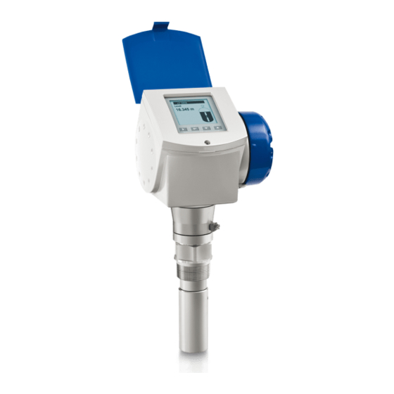
KROHNE OPTIWAVE 7300 C Handbook
24 ghz non-contact radar (fmcw) level meter for distance, level, volume and mass measurement of liquids
Hide thumbs
Also See for OPTIWAVE 7300 C:
- Handbook (200 pages) ,
- Quick start manual (36 pages) ,
- Supplementary instructions manual (28 pages)
Table of Contents
Advertisement
Quick Links
Advertisement
Table of Contents

Related Manuals for KROHNE OPTIWAVE 7300 C


Summary of Contents for KROHNE OPTIWAVE 7300 C
- Page 1 OPTIWAVE 7300 C OPTIWAVE 7300 C OPTIWAVE 7300 C Handbook Handbook Handbook Handbook 24 GHz Non-contact Radar (FMCW) Level Meter for distance, level, volume and mass measurement of liquids © KROHNE 03/2015 - 4000172406 - HB OPTIWAVE 7300 R08 en...
- Page 2 All rights reserved. It is prohibited to reproduce this documentation, or any part thereof, without the prior written authorisation of KROHNE Messtechnik GmbH. Subject to change without notice. Copyright 2015 by KROHNE Messtechnik GmbH - Ludwig-Krohne-Str. 5 - 47058 Duisburg (Germany) www.krohne.com 03/2015 - 4000172406 - HB OPTIWAVE 7300 R08 en...
-
Page 3: Table Of Contents
CONTENTS OPTIWAVE 7300 C 1 Safety instructions 1.1 Software history ....................... 7 1.2 Intended use ........................7 1.3 Certification ........................8 1.4 Electromagnetic compatibility ..................8 1.5 Radio approvals ........................ 8 1.5.1 European Union (EU)....................... 8 1.5.2 U.S.A. and Canada......................... 10 1.6 Safety instructions from the manufacturer .............. - Page 4 CONTENTS OPTIWAVE 7300 C 4 Electrical connections 4.1 Safety instructions......................41 4.2 Electrical installation: outputs 1 and 2 ................41 4.2.1 Non-Ex devices ........................42 4.2.2 Devices for hazardous locations................... 43 4.3 Protection category ......................43 4.4 Networks ........................44 4.4.1 General information......................
- Page 5 CONTENTS OPTIWAVE 7300 C 7 Service 7.1 Periodic maintenance..................... 83 7.2 How to clean the top surface of the device ..............83 7.3 How to clean horn antennas under process conditions ..........84 7.4 How to replace device components ................85 7.4.1 Service warranty ........................
- Page 6 CONTENTS OPTIWAVE 7300 C 10 Appendix 10.1 Order code ........................124 10.2 List of spare parts ...................... 130 10.3 List of accessories...................... 133 10.4 Glossary ........................135 11 Notes www.krohne.com 03/2015 - 4000172406 - HB OPTIWAVE 7300 R08 en...
-
Page 7: Safety Instructions
SAFETY INSTRUCTIONS OPTIWAVE 7300 C 1.1 Software history Data about software revisions is shown in the Supervisor menu. Go to Test > Information > Test > Information > Test > Information > Test > Information > Function description Device ID... -
Page 8: Certification
SAFETY INSTRUCTIONS OPTIWAVE 7300 C 1.3 Certification DANGER! For devices used in hazardous areas, additional safety notes apply; please refer to the Ex documentation. In accordance with the commitment to customer service and safety, the device described in this document meets the following safety requirements: •... - Page 9 SAFETY INSTRUCTIONS OPTIWAVE 7300 C Figure 1-1: Radio approval information on the nameplate 1 CE sign 2 Notified body number (0682 = CETECOM) 3 Class II identifier According to ETSI EN 302 372-2 (2011), the radiated power outside a metallic tank is less than -30 dBm.
-
Page 10: And Canada
SAFETY INSTRUCTIONS OPTIWAVE 7300 C Locations of radio astronomy sites (stations) in Europe and northern Eurasia Country Name of the station Location Latitude, ϕ Longitude, λ Finland Metsähovi 60°13'04" N 24°23'37" E Tuorla 60°24'56" N 22°26'31" E France Plateau de Bure 44°38'01"... -
Page 11: Safety Instructions From The Manufacturer
SAFETY INSTRUCTIONS OPTIWAVE 7300 C 1.6 Safety instructions from the manufacturer 1.6.1 Copyright and data protection The contents of this document have been created with great care. Nevertheless, we provide no guarantee that the contents are correct, complete or up-to-date. -
Page 12: Product Liability And Warranty
SAFETY INSTRUCTIONS OPTIWAVE 7300 C 1.6.3 Product liability and warranty The operator shall bear responsibility for the suitability of the device for the specific purpose. The manufacturer accepts no liability for the consequences of misuse by the operator. Improper installation or operation of the devices (systems) will cause the warranty to be void. The respective "Standard Terms and Conditions"... -
Page 13: Warnings And Symbols Used
SAFETY INSTRUCTIONS OPTIWAVE 7300 C 1.6.5 Warnings and symbols used Safety warnings are indicated by the following symbols. DANGER! This warning refers to the immediate danger when working with electricity. DANGER! This warning refers to the immediate danger of burns caused by heat or hot surfaces. -
Page 14: Device Description
DEVICE DESCRIPTION OPTIWAVE 7300 C 2.1 Scope of delivery INFORMATION! Do a check of the packing list to make sure that you have all the elements given in the order. Scope of delivery – horn antenna Figure 2-1: Scope of delivery – horn antenna... - Page 15 DEVICE DESCRIPTION OPTIWAVE 7300 C Scope of delivery – hygienic antenna Figure 2-3: Scope of delivery – hygienic antenna 1 Signal converter and antenna in compact version 2 Quick Start 3 DVD-ROM (including Handbook, Quick Start, Technical Datasheet, and related software)
-
Page 16: Device Description
DEVICE DESCRIPTION OPTIWAVE 7300 C 2.2 Device description This device is a 24 GHz FMCW-radar level transmitter. It is a non-contact technology and is 2- wire loop-powered. It is designed to measure the distance, level, mass, volume and reflectivity of liquids, pastes and slurries. -
Page 17: Visual Check
DEVICE DESCRIPTION OPTIWAVE 7300 C 2.3 Visual Check WARNING! If the display screen glass is broken, do not touch. INFORMATION! Inspect the packaging carefully for damages or signs of rough handling. Report damage to the carrier and to the local office of the manufacturer. -
Page 18: Nameplates
DEVICE DESCRIPTION OPTIWAVE 7300 C 2.4 Nameplates INFORMATION! Look at the device nameplate to ensure that the device is delivered according to your order. Check for the correct supply voltage printed on the nameplate. 2.4.1 Non-Ex nameplate Figure 2-6: Non-Ex nameplate 1 Indicator arrow to cable entry / cable entry size. -
Page 19: Installation
INSTALLATION OPTIWAVE 7300 C 3.1 General notes on installation INFORMATION! Inspect the packaging carefully for damages or signs of rough handling. Report damage to the carrier and to the local office of the manufacturer. INFORMATION! Do a check of the packing list to make sure that you have all the elements given in the order. -
Page 20: Transport
INSTALLATION OPTIWAVE 7300 C 3.3 Transport Figure 3-2: How to lift the device 1 Remove the converter before you lift the device with a hoist. WARNING! Lift the device carefully to prevent damage to the antenna. 3.4 Pre-installation requirements INFORMATION! Obey the precautions that follow to make sure that the device is correctly installed. -
Page 21: How To Prepare The Tank Before You Install The Device
INSTALLATION OPTIWAVE 7300 C 3.5 How to prepare the tank before you install the device CAUTION! To avoid measuring errors and device malfunction, obey these precautions. 3.5.1 Pressure and temperature ranges Figure 3-3: Pressure and temperature ranges 1 Flange temperature ®... -
Page 22: Recommended Mounting Position
INSTALLATION OPTIWAVE 7300 C 3.5.2 Recommended mounting position CAUTION! Follow these recommendations to make sure that the device measures correctly. Figure 3-4: Recommended nozzle position for liquids, pastes and slurries 1 Nozzles for DN40 or DN50 Horn antennas, or DN50 Hygienic antenna... -
Page 23: Theoretical Data For Hygienic Applications
INSTALLATION OPTIWAVE 7300 C Figure 3-5: Product inlets 1 The device is in the correct position. 2 The device is too near to the product inlet. Figure 3-6: More than 1 FMCW radar level meter can be operated in a tank More than 1 FMCW radar level meter can be operated in a tank. -
Page 24: Installation Recommendations For Liquids
INSTALLATION OPTIWAVE 7300 C 3.6 Installation recommendations for liquids 3.6.1 General requirements INFORMATION! We recommend that you configure the device when the tank is empty. Figure 3-8: General Installation recommendations 1 Do not tilt the device more than 2° 2 We recommend that you do an empty spectrum recording if there are too many obstacles in the radar beam (for more... -
Page 25: Standpipes (Stilling Wells And Bypass Chambers)
INSTALLATION OPTIWAVE 7300 C 3.6.2 Standpipes (stilling wells and bypass chambers) Use a standpipe if: • There is highly conductive foam in the tank. • The liquid is very turbulent or agitated. • There are too many other objects in the tank. - Page 26 INSTALLATION OPTIWAVE 7300 C Stilling wells - general notes Installation in tanks containing one liquid and foam • Drill an air circulation hole (max. Ø10 mm / 0.4¨) in the stilling well above the maximum level. • Remove the burr from the hole.
- Page 27 INSTALLATION OPTIWAVE 7300 C Stilling wells: horizontal cylindrical tanks We recommend that you install the device in a stilling well if the device: • is for a horizontal cylindrical tank, • is in a metallic tank, • measures a product with a high dielectric constant and •...
-
Page 28: How To Install The Device On The Tank
INSTALLATION OPTIWAVE 7300 C Bypass chambers Installation next to tanks containing one liquid and foam • The top process connection of the bypass chamber must be above the maximum level of liquid. • The bottom process connection of the bypass chamber must be below the lowest measured level of liquid. - Page 29 INSTALLATION OPTIWAVE 7300 C Requirements for flange connections Figure 3-13: Flange connection If the antenna is smaller than the process connection: • Make sure the flange on the nozzle is level. • Make sure that you use the applicable gasket for the flange dimensions and the process.
-
Page 30: How To Install A Device With A Threaded Connection
INSTALLATION OPTIWAVE 7300 C WARNING! If you attach the antenna in a closed space, make sure that there is a good airflow in the area. Make sure that a person not in the tank can always hear you. If the antenna is larger than the process connection: •... - Page 31 INSTALLATION OPTIWAVE 7300 C Figure 3-16: How to attach the device if the antenna is larger than the process connection Equipment needed: • 3 mm Allen wrench (not supplied) WARNING! If you attach the antenna in a closed space, make sure that there is a good airflow in the area.
-
Page 32: How To Install A Device With A Hygienic Connection
INSTALLATION OPTIWAVE 7300 C If the process connection of the device is smaller than the process connection on the tank: • Make sure the tank connection is level. • Use a plate with a slot or a different applicable procedure to adapt the device to the tank. - Page 33 INSTALLATION OPTIWAVE 7300 C Tri-Clamp® Equipment needed: • Device with Tri-Clamp® adaptor • Gasket (not supplied) • Band clamp (not supplied) ® Figure 3-18: Tri-Clamp connection 1 Tank socket 2 Band clamp How to attach a device with a Tri-Clamp® connection •...
- Page 34 INSTALLATION OPTIWAVE 7300 C DIN 11851 Equipment needed: • Device with a DIN 11851 adaptor • Gasket (not supplied) • DIN 11851 nut Figure 3-19: DIN 11851 connection 1 Tank socket 2 Nut for DIN 11851 connection How to attach a device with a DIN 11851 connection •...
- Page 35 INSTALLATION OPTIWAVE 7300 C Equipment needed: • Device with a SMS adaptor • Gasket (not supplied) • SMS nut Figure 3-20: SMS connection 1 Tank socket 2 Nut for SMS connection How to attach a device with a SMS connection •...
-
Page 36: How To Attach Antenna Extensions
INSTALLATION OPTIWAVE 7300 C VARIVENT® Equipment needed: • Device with a VARIVENT® adaptor • Clamp (not supplied) Figure 3-21: VARIVENT® connection 1 Tank socket (VARIVENT® Access Unit – not supplied) How to attach a device with a VARIVENT® connection • Make sure the tank connection is level. - Page 37 INSTALLATION OPTIWAVE 7300 C ® Use the display screen or HART communication (PACTware™). Antenna extension = antenna extension length × number of extensions. • If you changed the antenna extension value in Supervisor Supervisor mode, also change the blocking Supervisor Supervisor distance value.
-
Page 38: How To Turn Or Remove The Signal Converter
INSTALLATION OPTIWAVE 7300 C 3.7.5 How to turn or remove the signal converter INFORMATION! The converter turns 360 . The converter can be removed from the process connection assembly ° under process conditions. Figure 3-24: How to turn or remove the signal converter... -
Page 39: How To Attach The Weather Protection To The Device
INSTALLATION OPTIWAVE 7300 C 3.7.6 How to attach the weather protection to the device Equipment needed: • Device. • Weather protection (option). • 10 mm wrench (not supplied). The overall dimensions of the weather protection are on page 104. Figure 3-25: Installation of the weather protection •... -
Page 40: How To Open The Weather Protection
INSTALLATION OPTIWAVE 7300 C 3.7.7 How to open the weather protection Equipment needed: • Weather protection attached to the device. • Large slotted tip screwdriver (not supplied). Figure 3-26: How to open the weather protection 1 Weather protection in its closed position 2 Weather protection in its open position. -
Page 41: Electrical Connections
ELECTRICAL CONNECTIONS OPTIWAVE 7300 C 4.1 Safety instructions DANGER! All work on the electrical connections may only be carried out with the power disconnected. Take note of the voltage data on the nameplate! DANGER! Observe the national regulations for electrical installations! DANGER! For devices used in hazardous areas, additional safety notes apply;... -
Page 42: Non-Ex Devices
ELECTRICAL CONNECTIONS OPTIWAVE 7300 C Procedure: • Remove the housing terminal compartment cover 1. • Connect the wires to the device. Obey the national electrical codes. • Make sure that the polarity of the wires is correct. • Attach the ground to 4 or 7. Both terminals are technically equivalent. -
Page 43: Devices For Hazardous Locations
ELECTRICAL CONNECTIONS OPTIWAVE 7300 C 4.2.2 Devices for hazardous locations DANGER! For electrical data for device operation in hazardous locations, refer to the related certificates of compliance and supplementary instructions (ATEX, IECEx, FM, CSA etc.). You can find this documentation on the DVD-ROM delivered with the device or it can be downloaded free of charge from the website (Download Center). -
Page 44: Networks
ELECTRICAL CONNECTIONS OPTIWAVE 7300 C 4.4 Networks 4.4.1 General information The device uses the HART® communication protocol. This protocol agrees with the HART® Communication Foundation standard. The device can be connected point-to-point. It can also operate in a multi-drop network of up to 15 devices. -
Page 45: Multi-Drop Networks
ELECTRICAL CONNECTIONS OPTIWAVE 7300 C 4.4.3 Multi-drop networks Figure 4-6: Multi-drop network (non-Ex) 1 Address of the device (n+1 for multidrop networks) 2 Address of the device (1 for multidrop networks) ® 3 4 mA + HART ® 4 Resistor for HART... -
Page 46: Start-Up
START-UP OPTIWAVE 7300 C 5.1 Start-up checklist Check these points before you energize the device: • Are all the wetted components (antenna, flange and gaskets) resistant to the product in the tank? • Does the information on the signal converter nameplate agree with the operating data? •... -
Page 47: Digital Display Screen
START-UP OPTIWAVE 7300 C 5.3 Digital display screen 5.3.1 Local display screen layout Figure 5-1: Local display screen layout 1 Error icon 2 Tag number or menu name 3 Selected menu item (gray text cannot be selected) 4 [ ] / [ ]: scroll up/scroll down 5 Keypad buttons (refer to the table below) 5.3.2 Keypad buttons... -
Page 48: How To Start The Device
START-UP OPTIWAVE 7300 C 5.3.4 How to start the device • Connect the converter to the power supply. • Energize the converter. After 30 seconds the screen will display "booting up", "starting up" and then the default screen will appear. -
Page 49: Remote Communication With The Ams™ Device Manager
START-UP OPTIWAVE 7300 C Figure 5-2: Screen from the PACTware™ user interface 1 DTM menu 2 Basic measurement information: level, current output and device status 3 Information for device identification 4 Configuration summary 5.5 Remote communication with the AMS™ Device Manager The AMS™... -
Page 50: Operation
OPERATION OPTIWAVE 7300 C 6.1 User modes Operator Operator Operator This mode displays measurement data. For more data, refer to Operator Operator mode on page 50. Supervisor Supervisor Supervisor Supervisor Use this mode to view parameters, commission the device, create tables for volume or mass measurement, change critical values to measure in difficult process conditions. - Page 51 OPERATION OPTIWAVE 7300 C Screens in operator mode Text and image Go to % current output Go to Text screen Go to screen screen Level [> > > > ] Level > Level > (Text image) [ ] / [ ]...
-
Page 52: Supervisor Mode
OPERATION OPTIWAVE 7300 C 6.3 Supervisor mode 6.3.1 General notes Configure your device in Supervisor Supervisor mode. You can: Supervisor Supervisor • Use the Quick Setup Quick Setup Quick Setup menus to configure your device quickly. For more data about quick setup... -
Page 53: Menu Overview
OPERATION OPTIWAVE 7300 C 6.3.3 Menu overview A Quick Setup Setup Mode Quick Link 1 (default: Error Records) Quick Link 2 (default: Measurement Quality) Quick Link 3 (default: Language) Quick Link 4 (default: Length Unit) Quick Link 5 (default: Display Mode) -
Page 54: Keypad Functions
OPERATION OPTIWAVE 7300 C 6.3.4 Keypad functions Menu navigation > Figure 6-1: Menu navigation 1 Menu selection bar 2 Header bar 3 Menu list 4 Menu item that is not available (in gray text) This is what you see when you are in the list of menus in supervisor mode. The functions of the... - Page 55 OPERATION OPTIWAVE 7300 C Lists of parameters in menu items > Figure 6-2: Lists of parameters in menu items 1 Parameter selection bar 2 Menu name 3 Parameter used at this time This is what you see when you choose a menu item that has a list of parameters. The functions of...
- Page 56 OPERATION OPTIWAVE 7300 C Values in menu items Figure 6-3: Values in menu items 1 Maximum value 2 Minimum value 3 Cursor on the digit to be changed 4 Menu name 5 Illustration of menu item 6 Error message This is what you see when you choose a menu item that has a value. The functions of the buttons...
- Page 57 OPERATION OPTIWAVE 7300 C If you push the buttons for 1 second, you can use these hotkey functions: Hotkey functions in supervisor mode Button Description Function Right Create a quick link Enter — Down — Screen displays information in English...
-
Page 58: Function Description
OPERATION OPTIWAVE 7300 C 6.3.5 Function description A. Quick setup Menu Step Function Function description Selection list Default A.1 Setup Mode A.1.1 A.1.1 Complete Complete This follows the steps given in This follows the steps given in A.1.1 A.1.1 Complete... - Page 59 OPERATION OPTIWAVE 7300 C Menu Step Function Function description Selection list Default A.1.3 A.1.3 A.1.3 A.1.3 Empty Spectrum Empty Spectrum Empty Spectrum Empty Spectrum Fixed and moving objects in the Fixed and moving objects in the Fixed and moving objects in the...
- Page 60 OPERATION OPTIWAVE 7300 C Menu Step Function Function description Selection list Default Sub- Conversion menu submenu [Mass] [Mass] [Mass] [Mass] Do you want to use Yes, No a free unit? Table Length Unit m, cm, mm, inch, ft, Free Unit Please select Select "Mass".
- Page 61 OPERATION OPTIWAVE 7300 C Menu Step Function Function description Selection list Default Current changes Save, Cancel Save must be saved or cancelled before proceeding A.1.5 A.1.5 A.1.5 A.1.5 Outputs Outputs Outputs Outputs Follow this procedure to Follow this procedure to...
- Page 62 OPERATION OPTIWAVE 7300 C Menu Step Function Function description Selection list Default A.2 Quick Link 1 Quick Link 1 Direct link to an item in the Go to a function in the Error Advanced Setup menu Advanced Setup menu and Records push [>...
- Page 63 OPERATION OPTIWAVE 7300 C B. Test Menu Function Function description Selection list Default B.1 Test B.1.1 Show Output 1 This displays analogue output 1 value Read only [mA]. If the device has the fast motion software option, this menu item is available, but the function is disabled and changes in menu item B.1.2 have...
- Page 64 OPERATION OPTIWAVE 7300 C Menu Function Function description Selection list Default B.2.7 Custom. Non-standard length unit for the Read only Length Unit conversion table. This is defined by the supervisor. Go to Supervisor > Supervisor > Supervisor > Supervisor >...
- Page 65 OPERATION OPTIWAVE 7300 C Menu Function Function description Selection list Default C.1.8 Overfill If this function is switched on, the Yes, No Detection device will monitor the level even if it is in the blocking distance. The displayed output stays fixed at the blocking...
- Page 66 OPERATION OPTIWAVE 7300 C Menu Function Function description Selection list Default C.1.16 Multiple Multiple reflections will cause the Yes, No Reflections device to display smaller readings. Objects in the tank, sharp corners, installation of the device on a large nozzle or at the centre of a dome roof can cause multiple reflections.
- Page 67 OPERATION OPTIWAVE 7300 C Menu Function Function description Selection list Default C.3.3 20 mA Setting Give a measurement value to 20 mA. min.-max: Depends on the If the device has the fast motion output function software option, this menu item is...
- Page 68 OPERATION OPTIWAVE 7300 C Menu Function Function description Selection list Default C.5 Device Setup C.5.1 C.5.1 C.5.1 C.5.1 Display Display Display Display To display the information you need, To display the information you need, To display the information you need,...
- Page 69 OPERATION OPTIWAVE 7300 C Menu Function Function description Selection list Default C.6.3 Restart If the device is not functioning properly, this menu item will restart the device. Push [^ ^ ^ ^ ] to confirm. 1 Fast motion software option: Output 1 supplies a constant current of 16 mA (HART) 2 Units and range depend on the output function, length unit and volume unit selected.
-
Page 70: Further Information On Device Configuration
OPERATION OPTIWAVE 7300 C 6.4 Further information on device configuration 6.4.1 Protection of the device settings The Passwords Passwords menu lets you change the supervisor password. Passwords Passwords How to change the supervisor password • Go to Supervisor > Advanced setup > Device setup > Passwords > Supervisor Supervisor >... -
Page 71: Linearisation
OPERATION OPTIWAVE 7300 C How to change from multidrop to point-to-point mode • Enter supervisor mode. • Go to Advanced Setup > Output 1 (HART) > HART Address Advanced Setup > Output 1 (HART) > HART Address Advanced Setup > Output 1 (HART) > HART Address. -
Page 72: Level Measurement
OPERATION OPTIWAVE 7300 C CAUTION! If the distance for 4 mA is set in the blocking distance, the device will not be able to use the full current output range. Figure 6-4: Distance measurement 1 Tank Height (C.1.2) 2 Reference Offset (C.1.10) 3 Blocking Distance (C.1.9) - Page 73 OPERATION OPTIWAVE 7300 C INFORMATION! If you move the tank bottom offset below the tank bottom, add this value when you give a level for the 4 and 20 mA current output settings. If you move the tank bottom offset above the tank bottom, subtract this value when you give a level for the 4 and 20 mA current output settings.
-
Page 74: How To Configure The Device To Measure Volume Or Mass
OPERATION OPTIWAVE 7300 C 6.4.6 How to configure the device to measure volume or mass The device can be configured to measure volume or mass. You can set up a strapping table in the conversion table in the device's Quick Setup Quick Setup Quick Setup menu. -
Page 75: How To Make A Filter To Remove Radar Signal Interference
OPERATION OPTIWAVE 7300 C 6.4.7 How to make a filter to remove radar signal interference If the device measures level in a tank that contains obstructions (agitator, supports, heating pipes etc.), these objects can cause radar signal interference (parasitic signals). You can use the empty spectrum function (menu item A.1.3) in the Quick Setup menu to make a filter to remove... -
Page 76: How To Measure Correctly In Tanks With Curved Or Conical Bottoms
OPERATION OPTIWAVE 7300 C If you select Yes Yes, the device will use the empty spectrum scan results to make a filter to remove radar signal interference. INFORMATION! For more data on empty spectrum scans, refer to Function description on page 58 table A. -
Page 77: Service Mode
OPERATION OPTIWAVE 7300 C Figure 6-8: Signal screen and the tank bottom reflection 1 Tank bottom offset (menu item C.1.11) 2 Tank height (menu item C.1.2) 3 Signal amplitude (in dB) 4 True position of the tank bottom 5 Offset position of the tank bottom... - Page 78 OPERATION OPTIWAVE 7300 C Figure 6-9: Indication of errors 1 Error/ warning symbol Enter the supervisor mode to either: • Do an error status check, or • Read the error records and get more data about the error. How to check the measurement quality •...
- Page 79 OPERATION OPTIWAVE 7300 C How to find the error records • Enter supervisor mode. • Go to Test > Information > Error Records Test > Information > Error Records Test > Information > Error Records. Test > Information > Error Records •...
-
Page 80: Error Handling
OPERATION OPTIWAVE 7300 C The time since the error occurred is measured in Days:Hours:Minutes:Seconds Days:Hours:Minutes:Seconds Days:Hours:Minutes:Seconds Days:Hours:Minutes:Seconds.The error is saved in the permanent memory of the device at intervals of 1 hour. It only includes the time when the device is energized. The counter continues when the device is switched back on. - Page 81 OPERATION OPTIWAVE 7300 C Error Message Error Description Corrective action code Measuring status Measurement is old This is a temporary error Check the voltage at the message. If the device cannot device terminals. Refer also get a measurement in this...
- Page 82 OPERATION OPTIWAVE 7300 C Error Message Error Description Corrective action code Peak and spectrum Spectrum quality is bad The quality of the spectrum is Check the device, tank and poor. If this message is the process. Reconfigure the temporarily shown, this will...
-
Page 83: Service
SERVICE OPTIWAVE 7300 C 7.1 Periodic maintenance In normal operational conditions, no maintenance is necessary. If it is necessary, maintenance must be done by approved personnel (the manufacturer or personnel approved by the manufacturer). INFORMATION! For more data about regular inspections and maintenance procedures for devices with Ex and other approvals, refer to the related supplementary instructions. -
Page 84: How To Clean Horn Antennas Under Process Conditions
SERVICE OPTIWAVE 7300 C 7.3 How to clean horn antennas under process conditions If it is possible that there will be build-up, a purging option is available for horn antennas. WARNING! Purge the antenna with a dry gas or liquid that is applicable to the process. -
Page 85: How To Replace Device Components
SERVICE OPTIWAVE 7300 C 7.4 How to replace device components 7.4.1 Service warranty Maintenance is not necessary for most applications. Servicing by the customer is limited by warranty to How to • The removal and installation of the signal converter housing. For more data, refer to turn or remove the signal converter on page 38. -
Page 86: Replacement Of The Display Cover
SERVICE OPTIWAVE 7300 C 7.4.2 Replacement of the display cover Figure 7-1: Removal of the device display cover www.krohne.com 03/2015 - 4000172406 - HB OPTIWAVE 7300 R08 en... - Page 87 SERVICE OPTIWAVE 7300 C Equipment needed (not supplied): • TORX T8 wrench. • 3 mm Allen wrench (for steps 2 and 4). WARNING! Disconnect the power supply How to remove the display 1 Remove the 2 small screws on the hinge of the blue sun cover with a TORX T8 wrench. Remove the sun cover.
-
Page 88: Replacement Of The Complete Electronic Module
SERVICE OPTIWAVE 7300 C 7.4.3 Replacement of the complete electronic module Figure 7-2: Removal of the complete electronic module www.krohne.com 03/2015 - 4000172406 - HB OPTIWAVE 7300 R08 en... - Page 89 SERVICE OPTIWAVE 7300 C Equipment needed (not supplied): • 3 mm Allen wrench (for steps 1 and 4). How to remove the back end and microwave unit 1 Loosen the screw on the display. Open the display. 2 Disconnect the power supply connector from the electronics block.
-
Page 90: Replacement Of The Terminal Module
SERVICE OPTIWAVE 7300 C 7.4.4 Replacement of the terminal module Figure 7-3: Removal of the terminal module www.krohne.com 03/2015 - 4000172406 - HB OPTIWAVE 7300 R08 en... - Page 91 SERVICE OPTIWAVE 7300 C Equipment needed (not supplied): • 2.5 mm Allen wrench for Aluminium (painted) housings; 3 mm Allen wrench for Stainless Steel housings (for step 1). • Small slotted tip screwdriver (for step 3). • TORX T10 wrench (for step 5).
-
Page 92: Spare Parts Availability
SERVICE OPTIWAVE 7300 C 7.5 Spare parts availability The manufacturer adheres to the basic principle that functionally adequate spare parts for each device or each important accessory part will be kept available for a period of 3 years after delivery of the last production run for the device. -
Page 93: Form (For Copying) To Accompany A Returned Device
SERVICE OPTIWAVE 7300 C 7.7.2 Form (for copying) to accompany a returned device Company: Address: Department: Name: Tel. no.: Fax no.: Manufacturer's order no. or serial no.: The device has been operated with the following medium: This medium is: radioactive... -
Page 94: Technical Data
TECHNICAL DATA OPTIWAVE 7300 C 8.1 Measuring principle A radar signal is emitted via an antenna, reflected from the product surface and received after a time t. The radar principle used is FMCW (Frequency Modulated Continuous Wave). The FMCW-radar transmits a high frequency signal whose frequency increases linearly during the measurement phase (called the frequency sweep). -
Page 95: Technical Data
TECHNICAL DATA OPTIWAVE 7300 C 8.2 Technical data INFORMATION! • The following data is provided for general applications. If you require data that is more relevant to your specific application, please contact us or your local sales office. Additional information (certificates, special tools, software,...) and complete product •... - Page 96 TECHNICAL DATA OPTIWAVE 7300 C Beam angle of antenna Horn DN40 / 1.5¨: 20° Horn DN50 / 2¨: 15° Horn / Sheet metal horn DN80 / 3¨: 10° Horn / Sheet metal horn DN100 / 4¨: 8° Sheet metal horn DN150 / 6¨: 6°...
- Page 97 TECHNICAL DATA OPTIWAVE 7300 C Pressure Pressure Pressure Pressure Operating pressure Drop antenna (PP): Drop antenna (PP): Drop antenna (PP): Drop antenna (PP): -1…16 barg / -14.5…232 psig; subject to process connection used and flange temperature Drop antenna (PTFE): Drop antenna (PTFE):...
- Page 98 TECHNICAL DATA OPTIWAVE 7300 C Feedthrough Standard: PEI (-50...+200°C / -58...+390°F – max. range. The feedthrough temperature limits must agree with the temperature limits of the gasket material and antenna type. If the distance piece option is not attached, the maximum temperature is +150°C / +300°F.)
- Page 99 TECHNICAL DATA OPTIWAVE 7300 C Resolution ±3 µA Temperature drift Typically 50 ppm/K Error signal High: 22 mA; Low: 3.6 mA acc. to NAMUR NE 43 Approvals and certification This device fulfils the statutory requirements of the EC directives. The manufacturer certifies successful testing of the product by applying the CE mark.
- Page 100 TECHNICAL DATA OPTIWAVE 7300 C Other standards and approvals Other standards and approvals Other standards and approvals Other standards and approvals Electromagnetic Compatibility Directive 2004/108/EC in conjunction with EN 61326-1 (2013) R & TTE Radio Equipment and Telecommunications Terminal Equipment Directive...
-
Page 101: Antenna Selection
TECHNICAL DATA OPTIWAVE 7300 C 8.3 Antenna selection The graphs below show which antenna to select for the application based on: • D, the measuring range, • ε , is the dielectric constant of the product being measured Figure 8-2: Selection of antenna for liquid applications (graph of distance in m against ε... -
Page 102: Guidelines For Maximum Operating Pressure
TECHNICAL DATA OPTIWAVE 7300 C 8.4 Guidelines for maximum operating pressure WARNING! Make sure that the devices are used within their operating limits. Figure 8-4: Pressure / temperature de-rating (EN 1092-1), flange and threaded connection, in °C and barg 1500... - Page 103 TECHNICAL DATA OPTIWAVE 7300 C INFORMATION! CRN certification CRN certification CRN certification CRN certification There is a CRN certification option for devices with process connections that agree with ASME standards. This certification is necessary for all devices that are installed on a pressure vessel and used in Canada.
-
Page 104: Dimensions And Weights
TECHNICAL DATA OPTIWAVE 7300 C 8.5 Dimensions and weights Housing Figure 8-8: Housing dimensions 1 Housing front view 2 Housing side view Dimensions and weights in mm and kg Dimensions [mm] Weights [kg] Housing 158.5 1 If fitted with standard cable glands... - Page 105 TECHNICAL DATA OPTIWAVE 7300 C Weather protection Figure 8-9: Dimensions of the weather protection option 1 Weather protection, back view 2 Weather protection, left side view Dimensions and weights in mm and kg Dimensions [mm] Weights [kg] Weather 231.5 protection...
- Page 106 TECHNICAL DATA OPTIWAVE 7300 C DN40/1.5¨ horn antenna versions Figure 8-10: DN40 or 1.5¨ horn antenna versions 1 DN40/1.5¨ horn antenna with G 1½ or 1½ NPT thread connection 2 DN40/1.5¨ horn antenna with flange connection Dimensions and weights in mm and kg...
- Page 107 TECHNICAL DATA OPTIWAVE 7300 C DN50/2¨ horn antenna versions Figure 8-11: DN50/2¨ horn antenna versions 1 DN50/2¨ horn antenna with G 1½ or 1½ NPT thread connection 2 DN50/2¨ horn antenna with flange connection Dimensions and weights in mm and kg...
- Page 108 TECHNICAL DATA OPTIWAVE 7300 C DN80/3¨ horn antenna versions Figure 8-12: DN80/3¨ horn antenna versions 1 DN80/3¨ horn antenna with G 1½ or 1½ NPT thread connection 2 DN80/3¨ horn antenna with flange connection Dimensions and weights in mm and kg...
- Page 109 TECHNICAL DATA OPTIWAVE 7300 C DN100/4¨ horn antenna versions Figure 8-13: DN100/4¨ horn antenna versions 1 DN100/4¨ horn antenna with G 1½ or 1½ NPT thread connection 2 DN100/4¨ horn antenna with flange connection Dimensions and weights in mm and kg...
- Page 110 TECHNICAL DATA OPTIWAVE 7300 C Sheet metal horn antenna versions Figure 8-14: DN80/3¨, DN100/4¨, DN150/6¨ and DN200/8¨ sheet metal horn antenna versions 1 Sheet metal horn antenna (DN80/3¨, DN100/4¨, DN150/6¨ or DN200/8¨) with G 1½ or 1½ NPT thread connection 2 Sheet metal horn antenna (DN80/3¨, DN100/4¨, DN150/6¨...
- Page 111 TECHNICAL DATA OPTIWAVE 7300 C Dimensions and weights in mm and kg Dimensions [mm] Weights [kg] Øi Thread DN80/3¨ connection DN100/4¨ DN150/6¨ DN200/8¨ Flange DN80/3¨ connection DN100/4¨ DN150/6¨ 14.4 DN200/8¨ 15.0 1 If fitted with standard cable glands 2 Additional antenna extensions of Ø39 × length 105 mm are available 3 With ¼...
- Page 112 TECHNICAL DATA OPTIWAVE 7300 C DN80/3¨ Drop antenna versions Figure 8-15: DN80/3¨ Drop antenna versions 1 DN80/3¨ Drop antenna with G 1½ or 1½ NPT thread connection 2 DN80/3¨ Drop antenna with flange connection 3 DN80/3¨ Drop antenna, with PP or PTFE flange plate protection option...
- Page 113 TECHNICAL DATA OPTIWAVE 7300 C DN150/6¨ Drop antenna versions (PP material option only) Figure 8-16: DN150/6¨ Drop antenna versions (PP material option only) 1 DN150/6¨ Drop antenna with flange connection 2 DN150/6¨ Drop antenna with thread connection 3 DN150/6¨ Drop antenna, with flange plate protection option...
- Page 114 TECHNICAL DATA OPTIWAVE 7300 C DN50/2¨ Hygienic antenna versions Figure 8-17: DN50/2¨ Hygienic antenna versions 1 DN50/2¨ Hygienic antenna with Neumo BioControl® connection 2 DN50/2¨ Hygienic antenna with Tri-Clamp® connection 3 DN50/2¨ Hygienic antenna with SMS connection 4 DN50/2¨ Hygienic antenna with DIN 11851 connection 5 DN50/2¨...
-
Page 115: Description Of Hart Interface
DESCRIPTION OF HART INTERFACE OPTIWAVE 7300 C 9.1 General description The HART® Protocol is an open digital communication protocol for industry. It is free to use by anyone. It is included in the software embedded in signal converters of HART-compatible devices. -
Page 116: Connection Variants
DESCRIPTION OF HART INTERFACE OPTIWAVE 7300 C ® HART identification codes and revision numbers Manufacturer ID: 0x45 Device: 0xE5 Device Revision: DD Revision ® HART Universal Revision: ≥ 1.8 FC 375/475 system SW.Rev.: ≥ 7.0 AMS version: PDM version: ≥ 1.2 FDT version: 9.3 Connection variants... -
Page 117: Hart® Device Variables
DESCRIPTION OF HART INTERFACE OPTIWAVE 7300 C 9.4 HART® device variables HART® device variable Code Type level linear distance linear level conversion linear level mass linear reflection linear distance conversion linear distance mass linear The HART® dynamic variables PV (Primary Variable), SV (Secondary Variable), TV (Third Variable) and QV (Fourth Variable) can be assigned to any of the device variables. -
Page 118: Asset Management Solutions (Ams)
DESCRIPTION OF HART INTERFACE OPTIWAVE 7300 C HART For more data, refer to ® menu tree for Basic-DD on page 119. 9.6 Asset Management Solutions (AMS) The Asset Management Solutions Device Manager (AMS) is a PC program from Emerson ®... -
Page 119: Hart ® Menu Tree For Basic-Dd
DESCRIPTION OF HART INTERFACE OPTIWAVE 7300 C ® 9.8 HART menu tree for Basic-DD Abbreviations of the following tables: • Optional, depending on device version and configuration • Read only 9.8.1 Overview Basic-DD menu tree (positions in menu tree) 1 Process Variables... - Page 120 DESCRIPTION OF HART INTERFACE OPTIWAVE 7300 C 3 Access Rights 1 Supervisor Password 2 Service Password 4 Test 1 Test 1 Distance I1 / 2 Set Ouput1 / 3 Level I2 / 4 Set Output2 / 5 Internal Test 2 Information...
-
Page 121: Hart ® Menu Tree For Ams
DESCRIPTION OF HART INTERFACE OPTIWAVE 7300 C 7 Service Variables 1 Service Parameters 2 Calibration Parameters 3 Maintenance Info 1 Service Number / 2 Service Date / 3 Operator 1 If it is necessary to change the settings, enter the password. The default password is 123412. - Page 122 DESCRIPTION OF HART INTERFACE OPTIWAVE 7300 C Output Selection Output Functions Primary Function / Secondary Function / Tertiary Function / Fourth Function Output 1 Output Range / Error Handling / Error Handling Delay Output 2 Output Range / Error Handling...
- Page 123 DESCRIPTION OF HART INTERFACE OPTIWAVE 7300 C Informational (Warning) Upper Current output1 has saturated / Upper Current output2 has saturated / Lower Current output1 has saturated / Lower Current output2 has saturated / Measurement Old / Measurement Tank Overfill / Measurement Tank Bottom...
-
Page 124: Appendix
VF70 4 OPTIWAVE 7300 C 24 GHz Non-contact Radar (FMCW) level meter for liquids OPTIWAVE 7300 C 24 GHz Non-contact Radar (FMCW) level meter for liquids OPTIWAVE 7300 C 24 GHz Non-contact Radar (FMCW) level meter for liquids... - Page 125 APPENDIX OPTIWAVE 7300 C Antenna type Antenna type Antenna type Antenna type Horn DN80 (Ø75 mm / 2.95¨) – long Horn DN40 (Ø39 mm / 1.54¨) – long Horn DN50 (Ø43 mm / 1.69¨) – long Horn DN80 (Ø75 mm / 2.95¨) – long – with purging system Horn DN40 (Ø39 mm / 1.54¨) –...
- Page 126 APPENDIX OPTIWAVE 7300 C Feedthrough / Temperature / Sealing Feedthrough / Temperature / Sealing Feedthrough / Temperature / Sealing Feedthrough / Temperature / Sealing Non-Ex devices with a Drop antenna X Standard / -40...+150°C (-40…+302°F) / FKM/FPM Standard / -50…+150°C (-58…+302°F) / EPDM Other devices Standard / -40...+150°C (-40…+302°F) / FKM/FPM...
- Page 127 APPENDIX OPTIWAVE 7300 C Process connection ASME Process connection ASME Process connection ASME Process connection ASME Without 1½ NPT 1½¨ 150 lb RF ASME B16.5 1½¨ 300 lb RF ASME B16.5 2¨ 150 lb RF ASME B16.5 2¨ 300 lb RF ASME B16.5 A 3¨...
- Page 128 Portuguese Japanese Chinese (simplified) A Russian Version Version Version Version KROHNE (RAL 9006 / RAL 5005) KROHNE USA (FCC 2 GHz) KROHNE USA (250 MHz) A KMIC L (for liquid applications) VF70 VF70 VF70 VF70 Order code (complete this code on the pages that follow)
- Page 129 APPENDIX OPTIWAVE 7300 C Other approval Other approval Other approval Other approval Without B EAC Russia C EAC Belarus K EAC Kazakhstan Calibration certificate Calibration certificate Calibration certificate Calibration certificate Without Calibration certificate 2 factory-default points for an accuracy of ±3 mm / ±0.12¨...
-
Page 130: List Of Spare Parts
APPENDIX OPTIWAVE 7300 C 10.2 List of spare parts We supply spare parts and accessories for this device. When you order a spare part or accessory, please give the reference numbers that follow: Figure 10-1: Spare parts www.krohne.com 03/2015 - 4000172406 - HB OPTIWAVE 7300 R08 en... - Page 131 APPENDIX OPTIWAVE 7300 C Part numbers for spare parts Item Description Quantity Part reference number Complete electronic module XF7040000000040000 Screws for the combined back end and HF modules F3177360000 HMI cover and cable (aluminium housing) XF7040000000050100 HMI cover and cable (stainless steel housing)
- Page 132 APPENDIX OPTIWAVE 7300 C Item Description Quantity Part reference number Terminal module with 2 outputs and the fast motion XF7040000000034000 software option (non-Ex) Terminal module with FOUNDATION fieldbus output XF704000000003A000 (non-Ex) Terminal module with FOUNDATION fieldbus output XF704200000003A000 (ATEX – Ex ia)
-
Page 133: List Of Accessories
APPENDIX OPTIWAVE 7300 C 10.3 List of accessories Figure 10-2: Accessories Part numbers for accessories Item Description Quantity Part reference number Plastic sun cover XF704000000000000A Pins for the plastic sun cover F3179990000 Stainless steel weather protection XF7040000000000001 Blind cover (with a gasket and screws) - Page 134 APPENDIX OPTIWAVE 7300 C Item Description Quantity Part reference number Wiring compartment cover (with a gasket) XF7040000000000004 Gasket for the wiring compartment cover F5091150000 Converter VIATOR RS232 / HART® XF704000000000000C Converter USB / HART® XF704000000000000D Disc (low-pressure flange). Bolt hole positions and XF70000010 dimensions agree with DN80 PN2.5...40 / 3¨...
-
Page 135: Glossary
APPENDIX OPTIWAVE 7300 C 10.4 Glossary Dead zone Dead zone Dead zone Dead zone Non-measurement zone. Dielectric constant Dielectric constant An electrical property of the product to be measured used in Radar Dielectric constant Dielectric constant measurement. Also known as εr, DK and relative permittivity. Defines the strength of the wave reflected back to the device's signal converter. - Page 136 APPENDIX OPTIWAVE 7300 C Mass Mass Total mass of tank contents. Mass Mass Operators Operators Operators Operators Users who can choose how to display measurements. They cannot configure the device in supervisor mode. PACTware PACTware PACTware PACTware™ Software that operates and configures field devices from a remote workstation.
- Page 137 APPENDIX OPTIWAVE 7300 C Figure 10-3: Measurement definitions: distance 1 Distance 2 Dead zone 3 Flange facing 4 Gas (Air) 5 Tank height 6 Ullage volume or mass Figure 10-4: Measurement definitions: level 1 Level 2 Volume or mass 03/2015 - 4000172406 - HB OPTIWAVE 7300 R08 en...
-
Page 138: Notes
NOTES OPTIWAVE 7300 C www.krohne.com 03/2015 - 4000172406 - HB OPTIWAVE 7300 R08 en... - Page 139 NOTES OPTIWAVE 7300 C 03/2015 - 4000172406 - HB OPTIWAVE 7300 R08 en www.krohne.com...
- Page 140 Measuring systems for the marine industry Head Office KROHNE Messtechnik GmbH Ludwig-Krohne-Str. 5 47058 Duisburg (Germany) Tel.:+49 203 301 0 Fax:+49 203 301 103 89 info@krohne.com The current list of all KROHNE contacts and addresses can be found at: www.krohne.com...
Need help?
Do you have a question about the OPTIWAVE 7300 C and is the answer not in the manual?
Questions and answers