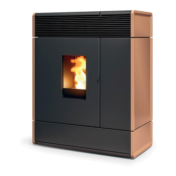
MCZ AKI Hydromatic 16 M1 Installation Manual
Hide thumbs
Also See for AKI Hydromatic 16 M1:
- Installation manual (64 pages) ,
- Installation manual (56 pages)

Related Manuals for MCZ AKI Hydromatic 16 M1


Summary of Contents for MCZ AKI Hydromatic 16 M1
- Page 1 INSTALLATION GUIDE PELLET STOVE AKI Hydromatic 16/24 M1 PART 1 - REGULATIONS AND ASSEMBLY Instructions in English...
-
Page 2: Table Of Contents
TABLE OF CONTENTS TABLE OF CONTENTS ....................II INTRODUCTION ......................1 1-WARNINGS AND WARRANTY CONDITIONS ..............2 2-INSTALLATION .......................10 3-DRAWINGS AND TECHNICAL SPECIFICATIONS ............19 4-UNPACKING ......................23 5 - SMOKE OUTLET CONNECTION ................26 6 CLADDING ASSEMBLY .....................29 7-OPENING THE DOORS .....................35 8-LOADING THE PELLETS ...................38 9-HYDRAULIC CONNECTION ..................40 10-ELECTRICAL CONNECTION ..................44... -
Page 3: Introduction
No part of this manual may be translated into other languages, adapted and/or reproduced, even in part, in other mechanical and/or electronic form or media, for photocopies, recordings or other, without the prior written authorisation of MCZ Group Spa. The company reserves the right to make changes to the product at any time without prior notice. The owner company reserves its rights according to law. -
Page 4: 1-Warnings And Warranty Conditions
1-WARNINGS AND WARRANTY CONDITIONS SAFETY WARNINGS • Installation, electrical connection, function test and maintenance must only be carried out by authorised and qualified personnel. • Install the product in accordance with all local and national legislation and regulations in force in the region or country. • Bad use or improper maintenance of the product can bring to a serious risk of explosion in the combustion chamber. - Page 5 1-WARNINGS AND WARRANTY CONDITIONS pipes, etc.). Avoid coming into contact with these parts without adequate protective clothing or suitable equipment, such as gloves with thermal protection or “cold handle” operating systems. • It is forbidden to operate the product with the door open or the glass broken.
- Page 6 1-WARNINGS AND WARRANTY CONDITIONS physical conditions and cause health problems. • Install the product in rooms that do not pose a fire hazard and are equipped with power and air supplies and smoke outlets. • In the event of fire in the chimney, turn off the device, disconnect it from the mains and do not open the door whatsoever.
- Page 7 SERVICE TECHNICIAN IMMEDIATELY. INFORMATION • If there are any issues, contact the retailer or a qualified technician authorised by MCZ. In the event of a repair, request the use of original spare parts. • Only use types of fuel recommended by MCZ (for Italy, pellets with a 6 mm diameter and pellets with a 6-8 mm diameter for other European countries), which must only be loaded with an automatic feed system.
- Page 8 1-WARNINGS AND WARRANTY CONDITIONS • If a “verification” mode is provided in the menu, set this function during the readings to ensure that no temperature modulation occurs due to an incorrect setting of the operating parameters. • Lastly, strictly comply with the sampling points specified in the regulations in terms of emissions as well as temperature WARRANTY CONDITIONS The firm covers the product,with the exception of the parts prone to normal wear that are listed below, for a period of 2 (two) years from the date of purchase as proved by:...
- Page 9 1-WARNINGS AND WARRANTY CONDITIONS Any technical operations on the product to remove the aforementioned defects and consequent damage must be agreed upon with the Technical Service Centre, who reserves the right to accept the relative job or not. However, said operations shall not be carried out under warranty but as technical support to be granted as part of any potentially and specifically agreed conditions and in accordance with the fees in force for the work to be carried out.
- Page 10 1-WARNINGS AND WARRANTY CONDITIONS SPARE PARTS In the event of a malfunction, consult the retailer who shall forward the call to the Technical Assistance Department. Only use original spare parts. The retailer or service centre can provide all necessary information regarding spare parts. We do not recommend waiting for the parts to get worn out before having them replaced.
- Page 11 1-WARNINGS AND WARRANTY CONDITIONS Our solid bio-combustible products, (hereinafter called “Products”) are designed and manufactured in compliance with one of the following European standard harmonised to Regulation (UE) no. 305/2011 for construction products: EN 14785: “Residential space heating appliances fired by wood pellets” EN 13240: “Roomheaters fired by solid fuel.”...
-
Page 12: 2-Installation
2-INSTALLATION The instructions in this chapter refer explicitly to the Italian installation regulation UNI 10683. In any case, always observe the regulations in force in the country of installation. PELLETS Wood pellets are manufactured by extruding sawdust which is produced during the processing of natural dried wood (without paint). The compactness of the material is guaranteed by the lignin contained in the wood itself and allows the pellets to be produced without glue or binders. - Page 13 2-INSTALLATION FOREWORD The installation position must be chosen according to the room, smoke extraction system and flue. Check with local authorities whether there are any restrictive regulations in force regarding the combustion air inlet, the smoke outlet system, the flue or the chimneypot. The manufacturer declines all responsibility in the event of installations that do not comply with the laws in force, incorrect room air exchange, electrical connection non-compliant with the standards and inappropriate use of the appliance.
- Page 14 2-INSTALLATION FOREWORD This Flue chapter has been drawn up with reference to the provisions of European Standards (EN13384 - EN1443 - EN1856 - EN1457). The chapter provides indications for installing an efficient and correct flue but is under no circumstances to substitute the regulations in force, which the qualified manufacturer must be in possession of.
- Page 15 2-INSTALLATION TECHNICAL SPECIFICATIONS Have the efficiency of the flue checked by an authorised technician. The flue must be sealed against flue gases, in a vertical direction without narrowing, be made with materials impermeable to smoke, condensation, thermally insulated and suitable to resist normal mechanical stress over time (we recommend fireplaces made of A/316 or refractory material with insulated round section double chamber).
- Page 16 2-INSTALLATION ROOF AT 60° ROOF AT 45° 45° 60° FIGURE 6 A = MIN. 2.60 metres A = MIN. 2.00 metres FIGURE 5 B = DISTANCE > 1.20 metres B = DISTANCE > 1.30 metres C = DISTANCE < 1.20 metres C = DISTANCE <...
- Page 17 2-INSTALLATION MAINTENANCE The flue must be kept clean, since the deposit of soot or unburnt oils reduces the cross-section, blocking the draught and thus compromising the efficient operation of the stove and, if large build-ups accumulate, can catch fire. The flue and chimneypot must be cleaned and checked by a qualified chimney sweep at least once a year.
- Page 18 2-INSTALLATION EXTERNAL AIR INLET It is mandatory to provide an adequate external air inlet that supplies the combustion air required for the product to work properly. The flow of air between the outside and the installation room may be direct, through an inlet in an external wall of the room (preferable solution see Figure 9 a), or indirect, via air intake from adjoining rooms and connecting permanently with the installation room (see Figure 9 b).
- Page 19 2-INSTALLATION DISTANCE (metres) The air inlet must be at a distance of: 1.5 m BELOW Doors, windows, smoke outlets, gaps, ..1.5 m HORIZONTALLY Doors, windows, smoke outlets, gaps, ..0.3 m ABOVE Doors, windows, smoke outlets, gaps, ..1.5 m AT A DISTANCE from smoke outlet CONNECTION TO THE FLUE...
- Page 20 2-INSTALLATION EXAMPLES OF CORRECT INSTALLATION 1. Installation of Ø120mm flue with hole for the passage of the pipe increased by: minimum 100mm around the pipe if next to non- flammable parts such as cement, brick, etc.; or minimum 300mm around the pipe (or as required by plate data) if next to flammable parts such as wood etc.
-
Page 21: 3-Drawings And Technical Specifications
3-DRAWINGS AND TECHNICAL SPECIFICATIONS DRAWINGS AND CHARACTERISTICS DIMENSIONS OF AKI HYDROMATIC 16/24 M1 STOVE (METAL CLADDING) Ø80 Ø50 Technical Dept. - All rights reserved - Reproduction prohibited... - Page 22 3-DRAWINGS AND TECHNICAL SPECIFICATIONS DIMENSIONS OF AKI HYDROMATIC 16/24 M1 STOVE (CERAMIC CLADDING) Ø80 Ø50...
- Page 23 3-DRAWINGS AND TECHNICAL SPECIFICATIONS TECHNICAL SPECIFICATIONS AKI Hydromatic 16 M1 Energy Efficiency Class Nominal output power 16.1 kW (13846 kcal/h) Nominal power output (H 12.8 kW (11008 kcal/h) Minimum output power 4.5 kW (3870 kcal/h) Minimum power output (H 3.0 kW (2580 kcal/h) Efficiency at Max 93.6%...
- Page 24 3-DRAWINGS AND TECHNICAL SPECIFICATIONS TECHNICAL SPECIFICATIONS AKI Hydromatic 24 M1 Energy Efficiency Class Nominal output power 23.9 kW (20554 kcal/h) Nominal power output (H 18.6 kW (15996 kcal/h) Minimum output power 4.5 kW (3870 kcal/h) Minimum power output (H 3.0 kW (2580 kcal/h) Efficiency at Max 92.0% Efficiency at Min...
-
Page 25: 4-Unpacking
4-UNPACKING PREPARATION AND UNPACKING The packaging consists of a recyclable cardboard box in line with RESY standards and a wooden pallet. All packaging materials can be reused for similar use or eventually disposed of as urban solid waste, in compliance with the regulations in force. After having removed the packaging make sure the product is intact. - Page 26 4-UNPACKING REMOVING THE FASTENING BRACKETS SUITE/CLUB/MUSA STOVES Remove the Suite/Club/Musa stoves from the pallet by removing the two screws ‘’u’’ and the plate ‘’s’’ from the stove foot. There are four brackets “s”.
- Page 27 4-UNPACKING Position the stove and connect it to the flue. Use the 4 adjustable feet (J) to get the stove correctly levelled so that the smoke outlet is lined up with the connecting pipe. If the stove needs to be connected to an outlet pipe which goes through the rear wall (to connect to the flue), take utmost care to make sure that the joint is not forced.
-
Page 28: Smoke Outlet Connection
5 - SMOKE OUTLET CONNECTION GENERAL WARNINGS The stove can have a rear or top smoke outlet. You must purchase the elbow (rear outlet) or the straight pipe (top outlet). REAR OUTLET CONNECTION To install the stove with rear smoke outlet, insert the elbow “T” (not supplied) into the inlet’ “r” and pass it through the hole “f” on the back of the stove. - Page 29 5 - SMOKE OUTLET CONNECTION TOP OUTLET CONNECTION To install the stove with top smoke outlet, proceed as follows: • take out the two screws “x” and remove the piece “S” • remove the knockout hole in the piece “S” to allow the top smoke outlet •...
- Page 30 5 - SMOKE OUTLET CONNECTION • insert the linear pipe “T” (not supplied) into the inlet “r” on the stove • secure the pipe “T” to the stove using the hook “S” and screw “z”...
-
Page 31: Cladding Assembly
6 CLADDING ASSEMBLY Live electrical parts: only power the product once it has been fully assembled. On delivery, the stove has no ceramic and/or metal cladding, as shown in the image below. Take the box with the ceramic sides “B” or metal sides “A” and prepare them for installation. The ceramic sides are already completely assembled (ceramics and mounting brackets), as well as the metal sides, and must be fitted as per the instructions on the following pages. - Page 32 6 CLADDING ASSEMBLY ASSEMBLY OF SIDE METAL PANEL You do not need to remove the top to fit the cladding. Simply lift the pellet cover “D” for the right side or the front cover “O” for the left side. • At the bottom of the stove, insert the holes “s”...
- Page 33 6 CLADDING ASSEMBLY • at the top, secure the panel “A” with the two screws supplied “x” • proceed the same way to fit the left panel “A” lifting the front cover “O” Technical Dept. - All rights reserved - Reproduction prohibited...
- Page 34 6 CLADDING ASSEMBLY ASSEMBLY OF SIDE CERAMIC PANEL You do not need to remove the top to fit the cladding. Simply lift the pellet cover “D” for the right side or the front cover “O” for the left side. • At the bottom of the stove, insert the holes “s”...
- Page 35 6 CLADDING ASSEMBLY • at the top, secure the panel “B” with the two screws supplied “x” • proceed the same way to fit the left panel “B” lifting the front cover “O” Technical Dept. - All rights reserved - Reproduction prohibited...
- Page 36 6 CLADDING ASSEMBLY REAR PANEL If maintenance must be performed on a component of the stove, the rear panel can be removed (if the distances from the walls allow it), otherwise, the maintenance can be performed by removing the side of the stove. To remove the rear panel, remove the four rear screws “a”...
-
Page 37: 7-Opening The Doors
7-OPENING THE DOORS DOOR OPENING To open the decorative door “E”, insert the cold handle “Z” into the hole in the handle and pull it towards you the same way as you open the firebox door “F”. Attention! Only open the doors when the stove is switched off and cold. DECORATIVE DOOR “E”... - Page 38 7-OPENING THE DOORS OPENING FRONT DOOR “O” To open the door “O” grip it in the part in front of the stove and lift it up. OPENING PELLET DOOR “P” To open the door “D” grip it on the side and pull it upwards.
- Page 39 7-OPENING THE DOORS OPENING LOWER DOOR “Q” To open the lower door “R” first of all you must have opened the decorative door “E”. Then grip the door by the rabbet in the middle and pull it towards you. Technical Dept. - All rights reserved - Reproduction prohibited...
-
Page 40: 8-Loading The Pellets
8-LOADING THE PELLETS LOADING THE PELLETS Fuel is loaded from the upper part of the stove by lifting the door “D”. Pour the pellets into the tank. This is easier if performed in two steps: Pour half of the contents into the tank and wait for the fuel to settle on the bottom. Then pour in the rest. - Page 41 8-LOADING THE PELLETS SAFETY WHAT TO DO IF SMOKE LEAKS INTO THE ROOM OR IN CASE OF EXPLOSION DAMAGING THE DEVICE: SWITCH IT OFF, VENTILATE THE ROOM AND IMMEDIATELY CONTACT THE INSTALLER/TECHNICIAN IN CHARGE OF ASSISTANCE. User Training In ALL cases, the technician in charge of installation and first-start-up MUST carry out a thorough handover of the appliance to the owner / end user.
-
Page 42: 9-Hydraulic Connection
9-HYDRAULIC CONNECTION PLUMBING SYSTEM CONNECTION IMPORTANT! The connection of the stove to the plumbing system must be carried out ONLY by specialised personnel who are capable of carrying out installation properly in compliance with current standards in the country of installation. The manufacturer will not be held responsible for damage to persons or property in the event of failed operation if the aforementioned warning is not complied with. - Page 43 9-HYDRAULIC CONNECTION DISCHARGE VALVE 3 bar The safety valve that can be inspected is found on the right side of the stove, under the pump. A high resistance pipe is connected, as per standard, to the safety discharge to drain the water until the bracket of the hydraulic connections. From that point, it is MANDATORY to connect a rubber hose that can withstand a temperature of 110°C (not supplied) and that reaches the outside for any water outlet.
- Page 44 9-HYDRAULIC CONNECTION CONNECTING THE SYSTEM Make the connections to the corresponding fittings shown in the diagram on the previous page. Make sure the pipes are not placed under tension or undersized. IT IS STRONGLY RECOMMENDED TO WASH THE ENTIRE SYSTEM BEFORE CONNECTING THE STOVE IN ORDER TO GET RID OF RESIDUES AND DEPOSITS.
- Page 45 9-HYDRAULIC CONNECTION END PIECE WITH A FILLING TAP (D) AND PRESSURE GAUGE (M) (ACCESSORY) MANUAL VENT VALVE UNDER THE TOP WATER CHARACTERISTICS The characteristics of the water used to fill the system are very important to prevent the build-up of mineral salts and the formation of incrustations along the pipes, in the boiler and in the heat exchangers.
-
Page 46: 10-Electrical Connection
10-ELECTRICAL CONNECTION ELECTRICAL CONNECTION First connect the power cable to the back of the stove and then to a wall socket. It is recommended to disconnect the power cable when the stove is not used. ELECTRICAL STOVE CONNECTION The cable must never come into contact with the smoke exhaust pipe or any other part of the stove. STOVE POWER SUPPLY Connect the power cable to the back of the stove and then to a wall socket. - Page 47 10-ELECTRICAL CONNECTION USB SOCKET In case of software update, the USB flash drive must be inserted directly in the circuit board (pos.25 in circuit board). Attention! The USB socket must be used by skilled technicians. Risk of damaging the product. Technical Dept.
- Page 48 Via La Croce n°8 33074 Vigonovo di Fontanafredda (PN) – ITALY Telephone: 0434/599599 a.s. Fax: 0434/599598 Internet: www.mcz.it e-mail: mcz@mcz.it 8902006500 REV 2 11/01/2021...
Need help?
Do you have a question about the AKI Hydromatic 16 M1 and is the answer not in the manual?
Questions and answers