Table of Contents
Advertisement
Quick Links
2010. 01. 15 2nd addition / Measuring mode added
2010.01.27 rev / I/O Pin configuration correction
2010.02.05 additional parameter 33,34,35,36
2010.03.26 page 21_ Added 7.8 Connecting to Hybrid HDC controller
2010.04.07 page 31-33_ Added 11.1-3 Protocol, data saving and monitoring
2010.04.15 page 30 _ Cable USB-RS232 code no. corrected
2010.05.11 page 23,24 pin 20 spare1 --> Mid-count signal correction
SCREW COUNTER MANUAL
SCOUT II
Advertisement
Table of Contents

Summary of Contents for Sehan Electools SCOUT II
- Page 1 2010.03.26 page 21_ Added 7.8 Connecting to Hybrid HDC controller 2010.04.07 page 31-33_ Added 11.1-3 Protocol, data saving and monitoring 2010.04.15 page 30 _ Cable USB-RS232 code no. corrected 2010.05.11 page 23,24 pin 20 spare1 --> Mid-count signal correction SCREW COUNTER MANUAL SCOUT II...
-
Page 2: Table Of Contents
INDEX Contents Page 1. Specification Main features 2. Main features 3. LAY OUT 4. Caution 5. Accessaries 6. Operation 6.1 Mode 6.2 Work mode 6.3 Log-in mode 6.4 Parameter mode 6.5 Measuring mode 6.6 Program & parameters 6.7 Parameters 7. Interface 7.1 25P I/O interface 7.2 Input ( Negative common wiring ) 7.3 Input ( Positive common wiring ) - Page 3 10.4 Start (pulse) + Stop (pulse) 11. RS-232C & USB COM port 11.1 Protocol details 11.2 Parameter change and save 11.3 Monitoring data output 12. PC software, SCOUT II Manager 12.1 Software install 12.2 How to use - 2 -...
-
Page 4: Specification Main Features
Program share ※ Only one(1) KT-38D with the version lower than v4.3 can be connected to Scout II. 2. Main features of SCOUT II - Maximum 5 screwdrivers can share one program of Scout ( 4 of KT-38D v4.3 or FT-40D through A,B,C,D port + 1 extra one through 25P I/O ) -
Page 5: Lay Out
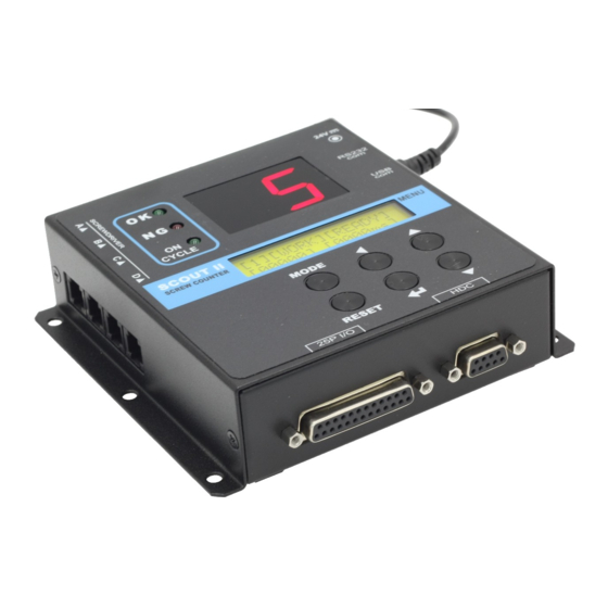
3. LAY OUT Fastening result by NG / OK Numeric LED for the number of fastening screw Power Input 24VDC,1A for HDC controller RS232C Com port Com port Menu LCD dia. 5mm 126.5 mm 136.5 mm 25P I/O port Hybrid screwdriver port - 4 -... -
Page 6: Caution
1 to 8. 7) Parameter setting is also possible on Scout Manager (pc software). It transmit the settings to Scout II. The settings on programs can be saved in csv format file. 4. Caution 1) The screw counter SCOUT II should be used with KT-38D or FT-40D controller only. -
Page 7: Accessaries
5. Accessaries ( Option items ) AC adapter(SMPS) model:PAG024M 24VDC,1A (part no. GCM6913) USB cable[A-B] type 1.8M KT-38D (part no. PELZ943) Connection Cable FT-40D RJ-45(8pin)-RJ11(6pin) RS232 cable /USB_A type Scout - KT-38D(FT-40D) 1.8M (part no. PELZ939) (7000007) 25P I/O cable (M-M) 1.8M (part no. -
Page 8: Operation
6. Operation 6.1 Mode By pressing the MODE button, it circulate Work, Work mode. Log-in, Parameter and Measuring (Log-in) Work means operating. Measuring Parameter Before parameter mode, password is required. Every settings is possible in Parameter mode. Once logged in, it circulate Work, Parameter and Measuring mode, until the power is off and on again. -
Page 9: Work Mode
6.2 Work mode Program # 1 to 8 Mode Judgement ( READY / OK / NG ) 1 WORK 【 READY 】 < 0000000 > 0000mS Fastenting time Total fastened screw number Move to next MODE when only cycle reset Decrease count number (-1) Program # UP (1 to 8) Program # DOWN... -
Page 10: Parameter Mode
6.4 Parameter mode Parameter # Description [ PARAMETER ] [01] CNT NUMBER 1 PLEASE ENTER [ 05 ] setting data Move to next Work MODE on Mode display Move the cursor left Number UP (Parameter #, data) Number DOWN Select Parameter # & Save data Move back without saving data - 9 -... -
Page 11: Measuring Mode
6.5 Measuring mode Total measured data Description [MEASURING] [00] [MEASURING] [02] [0000ms] [0000ms] [PROGRAM NO: 1 ] ▲ Min time Max time Display ▼ select ▲ Program # to be linked and [MEASURING] [00] saved with the current ▼ [0000] [AVG:0000] Min/Max data last data Average value... -
Page 12: Program & Parameters
6.6 Program # and parameters The program numbers from 1 to 8 are effected together with parameter 1~8 for number of screws, P9~16 for minimum tightening time, P17~24 for maximum tightening time. 1st data 2nd data 3rd data Number of Program # Min. -
Page 13: Parameters
6.7 Parameters Name Specification Default P01- Program # Save total number of screws on P1-8. P09- Minimum tightening Minimum screw tightening time time Input : 0.000 - 9.999 sec ( "0" : No use ) P17- Maximum tightening Maximum screw tightening time time Input : 0.000 - 9.999 sec ( "0"... - Page 14 Name Specification Default Select one of followings 0 : Not use Fastening buzzer 1 : OK only 2 : NG only 3 : OK + NG Select one of followings 0 : Not use Cycle buzzer 1 : OK only 2 : NG only 3 : OK + NG Select Reset key Enable / Disable...
-
Page 15: Interface
7. Interface 7.1 25P I/O interface details The configuration of 25P I/O port for remote control is as below PIN no. Configuration IN / OUT External Motor Run signal External Torque Up signal Cycle Start Cycle Stop Cycle Reset INPUT Driver Lock (to Controller) Spare 1... -
Page 16: Input ( Negative Common Wiring )
(Negative(-) Common wiring) 7.2 INPUT External power (24VDC+) SCOUT II External motor RUN External torque up Cycle Start Cycle Stop Cycle reset Driver Lock Spare 1 Input COM Return 24V(-) - 15 -... -
Page 17: Input ( Positive Common Wiring )
(Positive(+) Common wiring) 7.4 INPUT Return 24V(-) SCOUT II External motor RUN External torque up Cycle Start Cycle Stop Cycle reset Driver Lock Spare 1 Input COM External power (24VDC+) - 16 -... -
Page 18: Output ( Positive Common Wiring )
(Negative(-) Common wiring) 7.4 OUTPUT External power (24V+) SCOUT II 24VDC, 100mA max Cycle complete OK Cycle complete NG Tightening OK Tightening NG Mid-count complete Driver Lock Spare 2 No use Output COM Return(24V-) - 17 -... -
Page 19: Output ( Negaitive Common Wiring )
(Positive(+) Common wiring) 7.5 OUTPUT Return(24V-) SCOUT II 24VDC, 100mA max Cycle complete OK Cycle complete NG Tightening OK Tightening NG Mid-count complete Driver Lock Spare 2 No use Output COM External power (24VDC+) - 18 -... -
Page 20: I/O Wiring Example #1 - Tower Lamp, Sol Valve
7.6 Wiring example #1 - Tower lamp, solenoid valve, sensors, switch Pin 25 Output com Pin 17 Cycle complete NG Pin 16 Cycle complete OK Positive DC12~24V Relay Negative DC12~24V Adapter AC220V Tower lamp D:₩sehan1₩해외업체₩DOGA₩Position controller₩sol valve.jpg AC220V DC12~24V Relay Solenoid valve - 19 -... -
Page 21: I/O Wiring Example #2 - Inter-Lock Of Two Driver
7.7 Wiring example #2 - Inter-Lock of two screwdriver with Mid-Count signal setting Driver A Driver B Pin 20 Mid-count Pin 25 Output com complete Relay Negative power DC24V Adapter Positive DC24V Dual Relay Pin 20 Mid-count complete Driver A pin 6 Ground Driver A pin 5 Lock 100mA Com A... - Page 22 ■ Customized cable details KT-38D SCOUT II KT-38D SCOUT II To Relay Pin configuration KT-38D ------ SCOUT II 1 ( x ) 2 -------------------------------- 6 (Torque up) 3 -------------------------------- 5 (Start) 4 -------------------------------- 4 (com ) 5 --------------- (x) 3 (Lock)
-
Page 23: Connecting To Hybrid Hdc Controller
The screw count number on P74 of Hybrid HDC controller can be changed by program selecting on Scout II through the RS-232 interface port. The only RS-232 (not USB) interface of HDC controller works with Scout II. The min/max tightening time on Scout does not work for Hybrid HDC controller. -
Page 24: Timing Chart
8. Timing Chart ( example ) number of fastening screw is supposed to be three(3) ) Start Stop Fastening OK Fastening NG Buzzer Cycle complete OK ○ NG ○ NG ○ NG ○ NG ○ NG ● OK ● OK ●... -
Page 25: Timing Chart Details For Ok / Ng Setup
9. Timing chart details for NG / OK set up 9-1 Fastening OK Start Stop set range Min. Max. fastening time fastening time 9-2 Fastening ERROR 1 - TIME LAPSE Start Stop set range Min. Max. fastening time fastening time - 24 -... -
Page 26: Fastening Ng ( Time Over )
9-3 Fastening ERROR 2 - TIME OVER Start Stop set range Min. Max. fastening time fastening time 9-4 Fastening ERROR 3 - NO TORQUE UP ( Most common mistake in assembly ) Start Torque Up No Torque Up Error P28 / Minimum time to judgement - 25 -... -
Page 27: Cycle Start / Stop In The Various Operating Condition
10. Cycle Start / Stop in the various operating conditions 10.1 Auto Start - Where fastening number count is not necessary It starts to count the number of fastening automatically just after cycle end with "0" display of counter, and repeats without any cycle start and stop signal for counting. "Auto Start"... -
Page 28: Start (Pulse) + Stop By Time Limit (Optional)
Example) the target screw number is "10" Verify OK/NG 1st screw fastening 10th screw fastening display Cycle complete OK out signal The above switch can be replace to the sensor as shown on right work piece distance working area optical sensor 10.3 Start (pulse) + Stop by time limit (Optional) - Automatic flow assembly line with pallet conveyor system which is controlled by The SCOUT cooperates with PLC for the signals of cycle start and cycle stop, in... - Page 29 If the time is limited on P27 and the fastening is not complete till the set time, Scout will verify the fastening NG at the set time. It can be clear to the target by pressing RESET button Example #1 ) Cycle start pulse signal with time limit on P27 Cycle Start by pulse Wall block Time limit on P27...
-
Page 30: Start (Pulse) + Stop (Pulse)
10.4 Start (pulse) + Stop (pulse) - Semi-auto flow assembly line with belt conveyor system - Scout gives the alert buzzer when the work-piece move out to the next process before the cycle completed. It have two signals for work-piece coming IN and OUT using the optical or magnetic sensors. -
Page 31: Rs-232C & Usb Com Port
11. RS-232C & USB communication port Scout II provides both RS-232C and USB communication port together with free PC software, SCOUT II Manager. The com port and cable specification is as below. RS-232C ■ RS-232C Port SCOUT II Pin no... -
Page 32: Protocol Details
The command for data request and response are same, but distinguished by the capital letter for request, the small letter for response. Description Command Direction Save the parameter SCOUT II (capital) monitoring Data output SCOUT II (small) - 31 -... -
Page 33: Parameter Change And Save
↓ ↓ H ------------- Hexa value of "A" in ASCII code 11.2 Parameter change and save 1) Save parameter ( PC --> Scout II ) STX S 1 : Parameter number ( 001 - 999 ) 2 : Data ( 0000 - 9999 ) ※... -
Page 34: Monitoring Data Output
3 : Fastening No Torque Up 4 : Cycle Error 5 : Cycle limit time over on P27 4 : Count Number displayed on Scout II FND ( Remained screw number ) 5 : OK / NG judgement ※ OK / NG judgement details... -
Page 35: Pc Software, Scout Ii Manager
- PC Operating System : MS Windows ( 2000, XP, Vista ) - Display : 800 x 600 ( Optimized ) The SCOUT II-Manager software require MS Dot Net framework v 2.0 or higher on your OS before installing. Window 2000 and XP can be updated with Dot Net framework on the download center of Microsoft web site. - Page 36 ① ④ ② ③ - 35 -...
Need help?
Do you have a question about the SCOUT II and is the answer not in the manual?
Questions and answers