Table of Contents
Advertisement
Quick Links
Advertisement
Table of Contents

Subscribe to Our Youtube Channel
Related Manuals for Core Health & Fitness THROWDOWN ALPHA BAG RACKS


Summary of Contents for Core Health & Fitness THROWDOWN ALPHA BAG RACKS
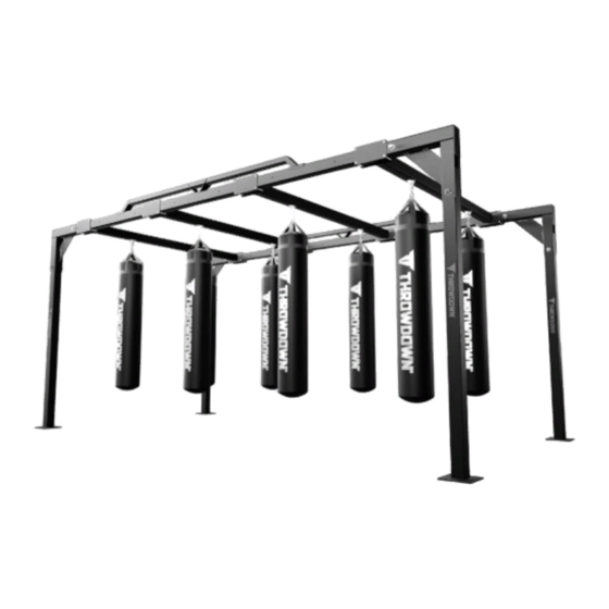
- Page 1 CORE HEALTH & FITNESS ALPHA BAG RACKS OWNER'S MANUAL...
-
Page 2: Table Of Contents
TABLE OF CONTENTS IMPORTANT SAFETY INSTRUCTIONS ........................2 PRODUCT SPECIFICATIONS ........................4 IMPORTANT LABEL LOCATIONS ........................8 ASSEMBLY ........................10 TOOLS ..............10 ASSEMBLY COMPONENTS ..............11 ONE-SIDED CORNER CONFIGURATIONS ..........13 9’ EXTENSION CONFIGURATIONS ............. 17 MAINTENANCE ........................21 TOOLS ..............21 MAINTENANCE SCHEDULE .............. -
Page 3: Important Safety Instructions
IMPORTANT SAFETY INSTRUCTIONS WARNING! Before using this product, it is essential to read the ENTIRE Owner’s Manual and ALL installation instructions. The Owner’s Manual describes equipment assembly and instructs members on how to use correctly and safely. Read all warnings posted on the machine. Health related injuries may result from incorrect or excessive use of exercise equipment. - Page 4 Wear proper exercise clothing and athletic shoes during a workout. Avoid wearing loose clothing. Tie back long hair and keep towels away from the moving parts. Face forward at all times and never attempt to turn around while the machine is moving.
-
Page 5: Product Specifications
PRODUCT SPECIFICATIONS Serial Label Fig. 2 ABR-1808-XX Pictured Desc: ALPHA BAG RACK, 9x18, 8 BAG SKU: ABR-1808-XX Installed Recreational Recreational Overall Weight Footprint Height Area (Min) Ceiling (Min) 1355 9’ 10” x 18’ 10” 8’ 11” 19’ 10” x 28’ 10” 9’... - Page 6 Serial Label Fig. 5 ABR-1820-XX Pictured ALPHA BAG RACK, 9x18, 20 BAG SKU: ABR-1820-XX Desc: Overall Weight Footprint Installed Height 8’ 11” 1880 12’ 8” x 22’ 4” 386 cm x 680 cm Recreational Recreational Ceiling Area (Min) (Min) 22’ 8” x 32’ 4” 9’...
- Page 7 Serial Label ABR-3616-XX Pictured Fig. 6 Desc: ALPHA BAG RACK, 9x36, 16 BAG SKU: ABR-3616-XX Installed Recreational Recreational Overall Weight Footprint Height Area (Min) Ceiling (Min) 1355 9’ 10” x 36’ 10” 8’ 11” 19’ 10” x 36’ 10” 9’ 0” 300 cm x 1123 cm 605 cm x 1122 cm Serial Label...
- Page 8 Serial Label Serial Label Fig. 9 ABR-3628-XX Pictured Fig. 10 ABR-3636-XX Pictured ALPHA BAG RACK, 9x36, 28 BAG ALPHA BAG RACK, 9x36, 36 BAG SKU: ABR-3628-XX Desc: SKU: ABR-3636-XX Desc: Overall Weight Footprint Installed Height Overall Weight Footprint Installed Height 8’...
-
Page 9: Important Label Locations
IMPORTANT LABEL LOCATIONS This page shows the location of the warning labels and communication stickers placed on the equipment as part of the manufacturing process. It is critical that owners maintain the integrity and placement of these stickers. If you find any stickers missing or damaged the replacement numbers are shown on the support site and following pages. - Page 10 81-00005 731-0517 THROWDOWN VERTICAL LOGO STICKER, WARNING, BOLT DOWN Notice: images are not to scale Page 9...
-
Page 11: Assembly
ASSEMBLY Metric Steel Bolts Torque Specifications Bolt Size Thread Pitch Torque, N-m (lbs-ft) WARNING: to reduce the risk of 1.25 10 to13.5 (8 to10) serious injury to persons using this 1.25 25.5 to 28.5 (19 to 21) equipment, all equipment MUST be secured (bolted and tightened) to a 10mm 1.75... -
Page 12: Assembly Components
ASSEMBLY COMPONENTS Bag Hangar Fig. 16 Fig. 14 T Connector Fig. 15 One-Sided Corner 9’ Extension Fig. 17 Fig. 19 9’ Beam Fig. 18 Upright Weldment Fig. 20 Beam Support Fig. 21 18’ Tube Page 11... - Page 13 31-00375 BOLT, HEX, M24 X 150 31-00373 BOLT, HEX, M12 X 90 31-00305 BOLT, HEX, M12 X 140 71-00389 NUT, BOLT ALTERNATIVE 31-00268 31-00267 WASHER, M12 NUT, NYLON LOCK, M12 31-00376 31-00377 NUT, NYLON LOCK, M24 WASHER, M24 Assembly Hardware Fig.
-
Page 14: One-Sided Corner Configurations
ONE-SIDED CORNER CONFIGURATIONS One-Sided Corner 18' Tube Beam Support 9' Beam Fig. 23 ABR-1808-XX Shown Units in this configuration: ABR-1808-XX ABR-3616-XX Components Components • Upright Weldment x4 • Upright Weldment x6 • One-Sided Corner Connector x4 • One-Sided Corner Connector x4 •... - Page 15 Procedure 1. Place the upright weldments in their install locations laying down. 2. Install a one-sided corner connector onto an upright weldment, then secure the upright weldment to the corner connector using two open- ended wrenches and the supplied hardware. Repeat this step three more times for a total of four one-sided corner connector upright weldment...
- Page 16 5. Stand up sides and secure with 9’beams, using 4 bolts and the supplied hardware at each connection point. Fig. 27 6. Secure beam supports using 3 bolts and the supplied hardware. Fig. 28 7. Secure the bag swivel to the crossbeam/bag Apply hangar (shown) Loctite 242...
- Page 17 8. Units with external bag hangars secure them to the 9’ beam assemblies. Fig. 30 Page 16...
-
Page 18: 9' Extension Configurations
9’ EXTENSION CONFIGURATIONS 9' Extension T Connector Beam Support 18' Tube 9' Beam Fig. 31 ABR-1812-XX Shown Units in this configuration: ABR-1816-XX ABR-1812-XX Components Components • Upright Weldment x4 • Upright Weldment x4 • T Connector x4 • T Connector x4 •... - Page 19 ABR-3624-XX ABR-3628-XX Components Components • Upright Weldment x6 • Upright Weldment x6 • T Connector x6 • T Connector x6 • 9’ Extension x2 • 9’ Extension x2 • 18’ Tube x4 • 18’ Tube x4 • 9’ Beam Assembly x8 •...
- Page 20 3. Units with 4 upright weldments connect the two assemblies built in Step 2 using two of the standard 18’ tubes and the supplied hardware. Fig. 33 4. Units with 6 upright weldments connect the two assemblies built in Step 2 using four of the 18’...
- Page 21 6. Secure beam supports using 3 bolts and the supplied hardware. Fig. 36 7. Secure the bag swivel to the crossbeam/bag Apply hangar (shown) Loctite 242 Apply Loctite 242 to the bottom of the bolt. Install the swivel including the antirotation bracket using an 8mm allen key and an adjustable wrench - ensure that the bearing is sandwiched between the two washers.
-
Page 22: Maintenance
MAINTENANCE TOOLS Working on this product will require basic and/or sometimes specialty tools based on the type of service that will be performed at any time. To assist, we recommend having the tools listed available when performing maintenance. Tool Screwdriver Set, Flat Socket Set, Metric 8mm Hex Bit Rubber Mallet or Dead-Blow Hammer... -
Page 23: Maintenance Schedule
MAINTENANCE SCHEDULE With durable, high performance components, this equipment is designed for heavy usage with minimal maintenance required. To keep it in top condition, perform regular daily, weekly and monthly preventive maintenance routines outlined below. The safety and integrity of this machine can only be maintained when the equipment is regularly examined for damage and wear and repaired. -
Page 24: Support & Service
SUPPORT & SERVICE CORE CONNECT Core Connect is your portal to all things service! Whether you need to order parts or register your warranty, Core Connect is the most effective way to get what you need fast and keep your facility operating smoothly. OFFERS 24-HOUR SELF SERVICE ACCESS TO: •... - Page 25 THIS PAGE INTENTIONALLY BLANK Page 24...
- Page 26 THIS PAGE INTENTIONALLY BLANK Page 25...
- Page 27 THIS PAGE INTENTIONALLY BLANK Page 26...
- Page 28 © 2021 CORE HEALTH & FITNESS LLC PART NUMBER 91-00065, REV A All rights reserved. Star Trac, the Star Trac logo and StairMaster are registered trademarks of Core Health & Fitness, LLC. Schwinn and Nautilus are registered trademarks of Nautilus Inc. used under license to Core Health & Fitness LLC. Throwdown is a registered trademark of Throwdown Industries, LLC.
Need help?
Do you have a question about the THROWDOWN ALPHA BAG RACKS and is the answer not in the manual?
Questions and answers