Table of Contents
Advertisement
Advertisement
Table of Contents

Related Manuals for Core Health & Fitness Stairmaster HIIT ROWER


Summary of Contents for Core Health & Fitness Stairmaster HIIT ROWER
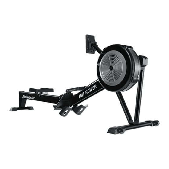
- Page 1 CORE HEALTH & FITNESS HIIT ROWER ® OWNER'S MANUAL...
-
Page 2: Table Of Contents
TABLE OF CONTENTS IMPORTANT SAFETY INSTRUCTIONS ........................2 PRODUCT DETAILS ........................4 MODEL SPECIFICATIONS ..............4 ASSEMBLY ........................6 PROCEDURE ..............7 USING THE HIIT ROWER ........................12 OPERATIONS ........................13 ATTACHING THE MONORAIL ..............13 DETACHING THE MONORAIL ..............15 HIIT CONSOLE ........................16 CONSOLE FEATURES .............. -
Page 3: Important Safety Instructions
IMPORTANT SAFETY INSTRUCTIONS WARNING! Before using this product, it is essential to read the ENTIRE Owner’s Manual and ALL installation instructions. The Owner’s Manual describes equipment assembly and instructs members on how to use correctly and safely. Read all warnings posted on the machine. Health related injuries may result from incorrect or excessive use of exercise equipment. - Page 4 Seat rollers can cause injury. Keep children, pets, clothes, and fingers away from seat rollers. Do not let handle fly into chain guide. 10. Pull straight back with both hands. Do not row with one hand only. Abuse of the chain can result in injury or damage to the equipment.
-
Page 5: Model Specifications
PRODUCT DETAILS This page shows the location of the warning labels and communication stickers placed on the equipment as part of the manufacturing process. It is critical that owners maintain the integrity and placement of these stickers. If you find any stickers missing or damaged the replacement numbers are shown on the support site and following pages. - Page 6 050-5597 DECAL, LOGO, HIIT ROWER, STAIRMASTER ROWER 050-5596 DECAL, LOGO, STAIRMASTER, STAIRMASTER ROWER AVG/MAX 050-5655 LABEL, GENERAL WARNING, HIIT ROWER Pace Units DETACH Console Keypad If damaged see Support and Service ATTACH 050-2142 STICKER,CAUTION,PINCH 050-5666 050-5666 LABEL, COLLAPSE, HIIT ROWER Page 5...
- Page 7 ASSEMBLY Required Tools: 716-0038-XX • Metric Allen Key Set LONG FORWARD SUPPORT, HIIT ROWER • Metric Allen Socket Set • Phillips Screwdriver • Torque Wrench 716-0039-XX • Metric Open-Ended Wrench Set SHORT FORWARD SUPPORT, HIIT ROWER 110-3672 NUT, M8 X 1.25, CS, NYLOC, BLK E-COAT, GR-10 110-4117 WASHER, M8, THICK, HARDENED, BEC 110-4099...
-
Page 8: Procedure
PROCEDURE 1. Place the shorter forward support (716-0039-XX) onto the front stabilizer (716-0082-XX) then place 740-7898 the longer forward support (716- 0038-XX) on top of the shorter support. 716-0038-XX 2. Use a torque wrench with a 5mm allen socket to secure the longer 716-0039-XX and shorter forward supports to the front stabilizer using four (4) - Page 9 Fig. 6 4. Bring the front half and back half of the rower together with the connection points elevated upwards, then push the lower hinge receiver located on the back half onto the pin, ensuring that the pin is fully seated into the lower receiver.
- Page 10 5. Bring the ends of each side of the rower upward so that the lower receiver rotates downward on the pin until the center latch on the front half of the rower locks completely down over the upper receiver on the back half of the rower.
- Page 11 110-3672 110-4117 716-0105 110-4099 Fig. 9 7. Carefully stand the rower upright so that it rests on the beam cap and front stabilizer, then install the pedal spacer (716-0105) between the foot rests. Secure it using one (1) piece each of the M8 x 110mm socket head cap screw (110-4099) and M8 nylock nut (110-3672), and two (2) pieces of the M8 thick washer (110-4117).
- Page 12 8. Use a phillips screwdriver to remove the installed screw securing the battery tray inside the console then remove the battery tray. 9. Install the two included C-cell batteries into the battery tray then reinstall the tray using the screw removed in the prior step. 10.
- Page 13 USING THE HIIT ROWER Position yourself on the seat, adjust the ratcheting heel cup so the canvas strap is across the bridge of your foot on both the right and left side. Secure strap to ensure a stable hold during the rowing motion Grasp the handle and pull towards your upper abdomen and the console will turn on.
-
Page 14: Attaching The Monorail
OPERATIONS ATTACHING THE MONORAIL 1. Grasp the front half of the rower by the foot strap and raise off the ground. Grasp back half of the rower and position over the top of the front half. CAUTION: Seat moves freely Fig. - Page 15 3. Once pin is aligned, while still lifting front half of rower, push firmly on the front of the back half to seat the pin completely into the groove. Fig. 18 Fig. 19 4. Once the pin is completely seated you can let the front half down to rest and the lock should move smoothly over the connection and click into place.
-
Page 16: Detaching The Monorail
Fig. 21 Storing the HIIT Rower The StairMaster HIIT Rower can be easily stored on end by disconnecting at the center point. CAUTION: Do not store the rower fully assembled in the vertical position as it may tip Page 15... -
Page 17: Console Features
HIIT CONSOLE CONSOLE FEATURES AVG/MAX Pace Units Fig. 22 HIIT Console To turn on console, press any button or start to workout. Console will track activity. Console displays SUMMARY mode after TIMEOUT period selected in MAINTENANCE mode or after pressing the ENTER button Press the AVG/MAX to see AVERAGE or MAX values displayed in speed and power windows. -
Page 18: Console Programs
CONSOLE PROGRAMS To start a program: Press to start. Use the buttons to select the desired time then press to set. Press again to start program. TIME Program Press to start. Use the buttons to select the desired distance then press to set. -
Page 19: Maintenance Mode
MAINTENANCE MODE Maintenance Mode allows access to service and diagnostic information, as well as provides the ability to adjust certain program default parameters. To enter Maintenance Mode: Within 15 seconds of waking the console, tap the buttons to enter Maintenance Mode. While in MAINTENANCE MODE pressing the button navigates between screens: •... -
Page 20: Tools
MAINTENANCE TOOLS Tool Working on this product will require basic and/or sometimes Metric Allen Key Set Screwdriver Set, Phillips specialty tools based on the type of service that will be Metric Open-Ended Wrench Set Screwdriver Set, Flat performed at any time. To assist, we recommend having the tools Large Adjustable Crescent Wrench Torque Wrench... -
Page 21: Maintenance Schedule
MAINTENANCE SCHEDULE With durable, high performance components, this equipment is designed for heavy usage with minimal maintenance required. To keep it in top condition, perform regular daily, weekly and monthly preventive maintenance routines outlined below. The safety and integrity of this machine can only be maintained when the equipment is regularly examined for damage and wear and repaired. -
Page 22: Bungee Installation
BUNGEE INSTALLATION If the bungee becomes slack or needs replacement follow this procedure to install or reinstall the bungee cord 1. Insert 3 inches of one end of the bungee cord through the eye of the termination clip then push the bungee into the tapered slot below the eye. - Page 23 3. Pass the bungee underneath and over the top of the 2nd pulley (P2) located next to the termination clip. Fig. 26 4. Pass the bungee over the top then underneath the floating front pulley tensioner. Fig. 27 5. Pass the pulley underneath then over the top of the 3rd pulley (P3).
- Page 24 7. Insert 3 inches of the remaining end of the bungee cord through the eye of the termination clip then push the bungee into the tapered slot below the eye. Pass the remaining length of the bungee through the open eyelet then back through the eye to lock the bungee in place as in Fig.
- Page 25 SUPPORT & SERVICE CORE CONNECT Core Connect is your portal to all things service! Whether you need to order parts or register your warranty, Core Connect is the most effective way to get what you need fast and keep your facility operating smoothly. OFFERS 24-HOUR SELF SERVICE ACCESS TO: •...
- Page 26 THIS PAGE INTENTIONALLY BLANK Page 25...
- Page 27 THIS PAGE INTENTIONALLY BLANK Page 26...
- Page 28 © 2021 CORE HEALTH & FITNESS LLC PART NUMBER 620-8675, REV E All rights reserved. Star Trac, the Star Trac logo and StairMaster are registered trademarks of Core Health & Fitness, LLC. Schwinn and Nautilus are registered trademarks of Nautilus Inc. used under license to Core Health & Fitness LLC. Throwdown is a registered trademark of Throwdown Industries, LLC.
Need help?
Do you have a question about the Stairmaster HIIT ROWER and is the answer not in the manual?
Questions and answers